Single-shot high-speed 3D imaging is important for reconstructions of dynamic objects. For fringe projection profilometry (FPP), however, it is still challenging to recover accurate 3D shapes of isolated objects by a single fringe image. In this paper, we demonstrate that the deep neural networks can be trained to directly recover the absolute phase from a unique fringe image that involves spatially multiplexed fringe patterns of different frequencies. The extracted phase is free from spectrum-aliasing problem which is hard to avoid for traditional spatial-multiplexing methods. Experiments on both static and dynamic scenes show that the proposed approach is robust to object motion and can obtain high-quality 3D reconstructions of isolated objects within a single fringe image.
Introduction
The development of information technology has accelerated human life into the digital three-dimensional (3D) world. Among many 3D optical measurement technologies, fringe projection profilometry (FPP) stands out as one of the most promising 3D imaging methods due to its non-contact, high spatial resolution, high measurement accuracy, and good system flexibility1-5. Nowadays, FPP has been widely applied in intelligent manufacturing, cultural relic scanning, human-computer interaction and some other fields6-9. In some important applications, such as rapid reverse engineering and online quality control10, 11, it is essential to obtain high-quality 3D information in continuously changing dynamic scenes12-14. For FPP, the projector projects a series of fringe patterns onto the target object, and then the camera captures these images modulated and deformed by the object. With the captured fringe patterns, the phase information of the measured object can be extracted through the fringe analysis algorithms. The most popular fringe analysis approaches are the Fourier transform (FT) methods15-19 and the phase-shifting (PS) methods20, 21. The FT approaches can utilize only a single high-frequency fringe pattern, where the phase information is recovered by applying a properly designed band-pass filter, such as the Hanning window, to extract phase-related spectrum information in the frequency domain. However, spectrum aliasing may cause low phase quality around discontinuities and isolated regions of the phase map. Unlike the FT methods, the PS technologies usually require three or more PS fringe patterns in the time domain to retrieve the phase map. Such methods are quite robust to ambient illumination and varying surface reflectivity, and can achieve pixel-wise phase measurement with high resolution and accuracy. For both FT and PS algorithms, the retrieved phase distribution is mathematically wrapped to principle values of arctangent function ranging between and . Consequently, the phase value is wrapped whenever there is a jump. To solve the phase ambiguity problem and establish a unique pixel correspondence between the camera and the projector to ensure correct 3D reconstruction, phase unwrapping must be carried out. One of the most commonly used phase unwrapping methods are the temporal phase unwrapping (TPU) algorithms22, which can obtain the absolute phase with the assistance of multi-frequency fringe images. However, such sacrifice of time resolution using a large number of images seriously decreases the 3D measurement efficiency of FPP. Therefore, in order to measure dynamic scenes, researchers usually reduce the fringe patterns required for phase unwrapping, thus to improve the efficiency of per 3D reconstruction23, 24. Ideally, the absolute depth is expected to be obtained by a single-shot fringe pattern.
The strategy of spatial frequency multiplexing is an effective single-frame 3D measurement technology25-32. The earliest idea of spatial frequency multiplexing was proposed by Takeda et al25. By combining multiple sinusoids with different two-component spatial carrier frequencies into a fringe pattern, they developed single-shot spatial-frequency multiplexing for the FT technique15 with the Chinese remainder theorem phase unwrapping technique (referred to as the G-S algorithm) to measure 3D objects with discontinuous and isolated surfaces. Another similar approach combined traditional multi-frame structure light pattern into a single composite pattern and can recover the depth data of moving or non-rigid object in real-time27. Although special fringe composite design is realized to separate the spectrum in the above work25, 27, it is still unable to avoid spectrum aliasing entirely. Therefore, the resulting low phase quality around discontinuities and isolated regions of the phase map makes these methods unable to be applied in high-accuracy 3D measurement field. Liu et al.23 proposed a dual-frequency composite PS scheme, where high-frequency wrapped phase with high-quality obtained by the PS method is unwrapped according to a low-frequency phase through three look-up tables (LUTs) algorithm. Although higher-quality 3D measurement is allowed, the 5 fringe patterns required by the PS method increase the sensitivity to dynamic scenes.
In recent years, many studies have used deep learning as a tool to solve or improve the measurement efficiency issues in traditional FPP33-38. Feng et al.33, 37 proposed a fringe analysis approach using deep learning. By combining the physical model of the traditional PS method, high-quality phase information can be extracted from a single-frame fringe image. Shi et al.39 proposed a deep learning-based fringe enhancement method to improve the phase imaging quality of the FT method. However, the above two methods can only achieve high-quality single-shot wrapped phase acquisition. In order to improve the efficiency of phase unwrapping, Yin et al.34 applied deep learning to perform TPU. Although a large number of projected images required by traditional TPU are reduced, at least two phase maps with one frequency and high frequency are needed. Qian et al.36 proposed a deep-learning-enabled geometric constraints and phase unwrapping method for single-shot absolute 3D shape measurement. Although robust phase unwrapping can be achieved on a single-frame projection, it is at the expense of increased hardware costs, where they used two cameras. Besides, they also combined deep learning and the color-coded technology to develop a single-shot absolute 3D shape measurement with color fringe projection profilometry38. However, this method will fail when measuring colored objects. In addition, there are also some end-to-end methods for linking fringe images and absolute depth information35, 40, 41. However, these methods may be difficult to obtain high-precision measurement results in practical applications, or may not guarantee stable fringe ambiguity removal.
Considering the traditional multi-frequency composite methods cannot guarantee single-frame high-accuracy 3D imaging, and inspired by the successful applications of deep learning in FPP, we propose a single-shot deep learning-based dual-frequency composite fringe projection profilometry, which can achieve spectrum-aliasing-free high-quality phase information retrieval, robust phase ambiguity removal and high-accuracy dynamic 3D shape measurement under the premise of only a single fringe projection image.
Different from the traditional end-to-end deep learning network that directly links the fringe image to absolute phase/depth35, 40, 41, we incorporate the concept of spatial frequency multiplexing in deep learning and design an unambiguous composite fringe image input to ensure that the networks have robust phase unwrapping performance. Besides, in order to provide the deep neural networks with the capability to overcome the serious spectrum aliasing problem that traditional spectrum separation technology cannot deal with, the fringe projection images without this problem are used to generate the aliasing-free labels. After proper training, the neural networks can directly recover robust absolute phase information through a composite fringe input image. Compared with traditional spatial frequency-multiplexing FT methods and deep learning techniques, our method can achieve higher quality phase information extraction as well as more robust phase unwrapping for objects with complex surface.
The remainder of this paper is organized as follows. In Section Principle, the basic principle of dual-frequency composite fringe projection profilometry, the acquisition of deep learning training data, the proposed deep learning-based composite fringe projection profilometry (DCFPP) method and the network architectures are introduced respectively. In Section Experiments and results, experimental verifications and comparison results are presented in detail. In the final Section Conclusions, we draw conclusions.
In FPP, to achieve 3D measurement for high-speed dynamic scenes, it is necessary to minimize the number of projection frame per 3D reconstruction31. In this work, we aim at challenging the physical limit of the number of fringe patterns required for 3D imaging, and retrieval 3D data from a single frame.
Generally, phase unwrapping is a crucial step in FPP, which establishes the unique correspondence between different views, thereby allowing absolute 3D reconstruction. Meanwhile, it is also the operation that most affects 3D measurement efficiency42. Therefore, the key to achieve single-shot 3D shape measurement is to remove phase ambiguity through single-frame fringe image. One of the conventional single-shot phase unwrapping methods is the spatial phase unwrapping algorithm43, which can directly recover the absolute phase from only single wrapped phase map through the phase values of spatially adjacent pixels. However, this method cannot uniquely determine the period numbers for the cases of large discontinuities or spatially isolated surfaces. Inspired by the recent successful applications of deep learning techniques on FPP, we consider applying deep neural networks to perform single-shot absolute phase acquisition. Since the reliability of deep learning largely depends on the raw input information, if the input itself is ambiguous, the network is by no means always reliable44. Thus, in order to robustly eliminate the phase singularity, we must design an unambiguous input pattern. To this end, refer to the traditional temporal phase unwrapping (TPU) algorithms22, which project a series of fringe patterns with different frequencies and determine the pixel-wise fringe orders through the unique wrapped phase distribution in the time domain, we superimpose the time domain information of different frequencies into the spatial domain to generate a composite fringe pattern. As the phase unwrapping network input, the composite pattern should have sufficient capability to resist phase ambiguity, in other words, multi-frequency information separated from the composite fringe pattern should achieve the unambiguous phase unwrapping. In this work, we design a dual-frequency composite fringe coding strategy, where two vertical sinusoidal fringe patterns with different frequencies are added. The composed fringe pattern (Fig. 1(a)) can be expressed as Eq. (1):
where is the image pixel coordinate, denotes the mean intensity, represents the amplitude, and are the wavelengths of the two hybrid sinusoidal fringe patterns with high and low frequencies, respectively. After illuminating the object with the composite fringe pattern through a digital projector, the intensities of the captured image can be expressed as:
where is the average intensity relating to the pattern brightness and background illumination, is the intensity modulation relating to the pattern contrast and surface reflectivity. Besides, the captured composite fringe image contains two phase information of high and low frequency, which are and respectively. In conventional fringe analysis methods, the extracted initial phase is the wrapped phase and with phase discontinuities due to the arctangent function45. Thus, phase unwrapping is required to remove the fringe ambiguities and correctly extract the absolute depth of the object42. The absolute phase maps corresponding to the wrapped phases of the hybrid sinusoidal fringe image can be represented as:
where and are the integer fringe order corresponding to the wrapped phases and , , denotes the number of the used fringes.
For two wrapped phase maps with different wavelengths, theoretically, we can use the traditional number-theoretical approach22, which is one of the TPU algorithms, to perform absolute phase unwrapping. The basic idea of this method relies on the fact that for suitable chosen fringe wavelengths and , their least common multiple determines the maximum range on the absolute phase axis within which the combination of wrapped phase values is unique46, 47. For a projection pattern with resolution, the selected two different wavelengths and should satisfy the following inequality to exclude phase ambiguity:
where represents the least common multiple function. That is to say, if (called the unambiguous range) can exceed the lateral resolution of the projected pattern, the phase ambiguity of the whole field can be eliminated. Specially, when the selected wavelengths are relatively prime, the function can be simplified to the multiplication of two wavelengths and the range of unambiguous phase becomes . After examining that the pairs of wrapped phase values are unique, the fringe orders and of the two phase maps can be determined.
Since the two sets of fringe patterns have different wavelengths ( and ), their absolute phase map should have the following relationship:
Combining Eqs. (3) and (5), we can get the following relation:
According to the number theory method, the fringe order pairs can be determined by the pre-computed lookup table (LUT) which establishes the unique correspondence between the left side (called function) and :
And the function can be expressed as:
where the represents a rounding function.
Refer to the optimal dual-frequency selection approaches48-50, the high-frequency is as high as possible to allow high-accuracy measurement, while the low-frequency cannot be too low to ensure the stability of the phase unwrapping, and the relative minimum gap of the combined frequencies should be as large as possible to improve the fault tolerance rate of phase unwrapping, we finally select the frequency combination of a high-frequency fringe with wavelength of 19 pixels and a low-frequency fringe with wavelength of 51 pixels to synthesize a single-frame composite fringe pattern. It can perform unambiguous phase unwrapping of points within the range of 969 pixels, which means that the whole field of the projected pattern can carry out absolute phase unwrapping.
Generate training data
The purpose of the data-driven-based deep learning network is to apply a large number of training data including the input values (the samples) and the ground-truth values (the targets/labels) to train a model, the output values predicted by which can be infinitely close to the ground-truth value. In this work, we aim at utilizing deep learning to predict high-quality the absolute phase map through a single fringe image.
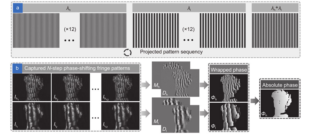
In order to make the trained deep neural network overcome the problem of spectrum aliasing, we use dual-frequency 12-step phase-shifting fringe patterns (Fig. 1(a)) to generate high-quality, high-precision, and spectrum-aliasing-free network labels. In particular, the selected two frequencies/wavelength and are the same as the composite dual-frequency/dual-wavelength of the composite fringe pattern. The captured high-frequency and low-frequency sinusoidal fringe images can be expressed as:
where and represent the intensity of the th captured image with high and low frequencies respectively, =1,2 12, and are the average intensity of and , and are the corresponding amplitude intensity maps. Then, the wrapped phase and can be obtained through the least-squares algorithm:
where set and as the numerator term and the denominator term of the arctangent function of wrapped phase , and set and as the numerator term and the denominator term of the arctangent function of wrapped phase . In order to eliminate the ambiguity of the high-frequency wrapped phase, we use the number-theoretical method (Eqs. (3), (7) and (8)) to unwrap the high-frequency wrapped phase into an absolute phase .
It should be emphasized that for the following three reasons, we do not adopt an end-to-end network structure that directly link the input fringe images to the output absolute phase/depth, but choose a network structure that predicting the numerator and denominator map of the wrapped phase arctangent function and a low-accuracy absolute phase map. 1) Since a single-frequency fringe image is insufficient to eliminate the phase/depth ambiguity in FPP while the multi-frequency fringe images can effectively remove this ambiguity through the TPU algorithm22, we use a single dual-frequency composite fringe image. As the network input, this composite image can not only retain the characteristics of a single frame projection, but also can be decomposed into two fringe images with different wavelengths/frequencies, which effectively removes the ambiguity of phase retrieval in essence and ensures that the absolute 3D shape measurement is not affected by any assumptions and prior knowledge, such as continuous surface, limited measurement range, geometric constraints. 2) Since the difficulty of establishing an accurate correspondence between the fringe intensity information and the high-accuracy absolute phase value, especially when the surface of the measured object contains sharp edges, discontinuities or large reflectivity variations, a simple input-output network structure only can usually obtain compromised imaging accuracy36. Based on this consideration, we use deep learning to predict a rough absolute phase containing the correct fringe order information from the designed composite fringe image. 3) Our deep neural network is trained to predict the numerator and denominator of the arctangent function, to bypass the difficulties associated with reproducing abrupt phase wraps, and thus, obtain a high-quality phase information33.
Therefore, in this work, the output of the network we constructed includes the numerator and denominator used to calculate high-quality phase information, as well as the rough absolute phase that provides the fringe order information. The labels of the training data corresponding to these outputs are the numerator , the denominator , and the high-frequency absolute phase . Figure 1(a) is our projection mode, and Fig. 1(b) shows set of fringe images and the labels generated from these images.
Figure 1.The process of generating training data. (a) The projection mode includes dual-frequency 12-step phase-shifting fringe projection patterns and dual-frequency composite fringe pattern. (b) A set of captured images and the corresponding labels contain numerator term, denominator term, and absolute phase map.
In addition, in order to enhance the network learning ability, we set an appropriate modulation threshold to mask the invalid points of the training data maps by using the modulation function (Eq. (11)) and the Mask function (Eq. (12)):
The value of threshold is set to 8, which is suitable for most of our measurement scenarios in this work.
Our purpose is to propose a single-shot fringe projection profilometry using deep learning, which can robustly recover high-quality absolute phase information from a composite fringe image, thus to perform high-accuracy 3D reconstruction. The flowchart of our proposed approach (DCFPP) is shown in Fig. 2.
Figure 2.Flowchart of our proposed approach. (a) Part of network training data sets. (b) Hardware system and the cross-section intensity distribution of the designed composite fringe pattern. (c) Test data and prediction results obtained by the training model.
Step 1: Selection of wavelength combination strategy to generate a composite fringe pattern. We choose two wavelength and with the unambiguous range pixels that satisfy the Eq. (4): (mentioned in Section Single-shot dual-frequency composite fringe projection profilometry), to generate the composite fringe image, which is sufficient to overcome phase ambiguity, as the input of the deep convolution neural network. In order to cover the entire dynamic range of the projector , we set in Eq. (1), and the composite pattern along with its cross-section intensity profile for , , , and is illustrated in Fig. 2(b).
Step 2: Preparation for network training data. According to the principle mentioned in Section Generate training data, we use two sets of 12-step PS fringe images with the same dual-wavelength and of composite pattern to calculate the numerator terms and the denominator terms of spectrum-aliasing-free high-frequency wrapped phases and absolute phases as the ground-truth values of the neural network.
Step 3: Training data preprocessing. Before feeding the input data and targets into the neural network, data preprocessing is required. Such operation aims at making the raw data more amenable to neural networks, including vectorization and normalization. First, all inputs and targets in a neural network must be tensors of floating-point, this step called data vectorization, and in the experiment, we transform them into array of shape (number of images, 640, 480). Besides, it should be noted that all network inputs and targets need to be converted to a format compatible with TensorFlow. In general, it is unreliable to input relatively large values or heterogeneous data (that is, the size between the input and the target may differ ten or even a thousand times) into a neural network. Thus, data normalization is required. We divide the input images by 255 to convert the previous gray values from 0–255 range to 0–1 range.
Step 4: Training the neural network models. After preparing the training data sets, including a large number of unambiguous input data sets and corresponding high-quality ground-truth data sets as shown in Fig. 2(a), we put these specially designed inputs and outputs into the U-Net networks, so that the network will have a more powerful absolute phase retrieval capability. In terms of phase information acquisition, such data-driven-based training network can overcome the problem of poor imaging quality caused by frequency aliasing and has the high-quality phase information extraction function like the traditional PS algorithms; And in terms of phase unwrapping, it can directly recover absolute phase from a single fringe image, so as to reach the physical limit the number of the fringe image required for a single 3D reconstruction and maximize the efficiency of 3D imaging. As shown in Fig. 2(c), we construct two deep convolutional neural networks with the same structure except the final convolution layer, referred to as the U-Net1 and U-Net2, to perform phase information extraction and phase unwrapping tasks, separately. The specific reasons for choosing two networks instead of one will be explained in Section Network architecture. Plenty of raw composite fringe images are fed into the two deep convolution neural networks, then U-Net1 will be trained with the corresponding and as ground-truth to generate a phase acquisition model, and U-Net2 will be trained with the corresponding absolute phases as the ground-truth to obtain a phase unwrapping model.
Step 5: Prediction for absolute phase. The U-Net1 network is responsible for predicting the numerator terms and the denominator terms of a single-frame composite fringe image. Then, taken the output results and into the arctangent function, the wrapped phase distribution can be extracted:
Simultaneously, the U-Net2 predicts the “coarse” absolute phase of the single-frame composite fringe image. Due to the environmental light, large surface reflectivity and discontinuities, it is hard to get high-quality phase information directly. Thus, feeding the wrapped phases from U-Net1 and the “coarse” absolute phase from U-Net2 into Eq. (14) to obtain the fringe order , the high-quality absolute phase can be recovered by Eq.(15).
Step 6: 3D shape reconstruction. Finally, by utilizing the pre-calibrated parameters of the FPP system51-53, 3D information of the objects can be reconstructed.
Network architecture
Next, we will further discuss the selection strategy and main architecture of the deep learning networks (Fig. 3). For the network architecture selection, we respectively use one U-Net network and two U-Net parallel networks to achieve phase retrieval and phase unwrapping. Figure 4 shows the comparison results of phase prediction using one U-Net network and two U-Net networks, from which we can draw conclusions: Using one U-Net network can predict an absolute phase of the object within the allowable error from different surface complexity, however, since this method directly outputs the absolute phase from the network, the absolute phase predict capability and quality of this end-to-end structure is worse than the result of two U-Net parallel networks. Thus, we use two U-Net parallel networks (marked as U-Net1 and U-Net2) to train the network models.
Figure 4.Comparison between one U-Net network and two U-Net networks (the proposed method). (a, d, g, j) The raw composite fringe images from four different measurement scenes. (b, e, h, k) The absolute phase result error between deep-learning-predicted value and the ground-truth value by using one U-Net network. (c, f, i, l) The absolute phase result error between deep-learning-predicted value and the ground-truth value by using two U-Net networks.
Taken U-Net1 network as an example to reveal the internal structure of the constructed networks, the input tensors of size (H, W, 1) are successively processed by a stack of convolutional layers, pooling layers, upsampling blocks, and concatenate layers. Each of convolutional layer represents a convolution operation, which extracts patches from its input feature map and applies the same transformation to all of these patches, producing an output feature map. For each convolution layer, the kernel size is 3×3 with convolution stride one and zero-padding, and it is activated by the rectified linear unit (ReLU) except for the last 1×1 convolution layer. The output of the convolutional layer is a 3D tensor of shape (h, w, d), whereh×w is the size of feature map input, d is the number of channels also representing filters that encode specific aspects of the input data. The number of channels is controlled by the first argument passed to the convolutional layers which is set to 32 in the proposed U-Net network. The role of pooling layer is to aggressively downsample feature maps, consists of extracting windows from the input feature maps and outputting the max value of each channel. Usually, max pooling layer is done with 2×2 windows and stride 2, in order to downsample the feature maps by a factor of 2. Thus, the size of composite image input H×W tend to shrink as it gets deeper in the network. After downsampling the input by five times for better extraction, the upsampling block needs to match the raw input size. Then, copy the convolutional layer and merge it with the upsampling layer into a concatenate layer. Besides, the ultimate goal of the network is to achieve a model that can be generalized, that is, perform well on never-seen-before data. However, overfitting is the central obstacle. The processing of fighting overfitting is regularization. In this network, we use the Dropout which is one of the most effective and most commonly used regularization techniques for neural networks to fight overfitting. The loss function we select in this neural network is mean squared error (MSE), which is used to compare these predictions with the targets and generate a loss value. The optimizer chooses the Adam optimization scheme, which is used to update the network weights with the loss value and achieve better gradient propagation. Finally, the network of layers chained together maps input data to predictions.
Experiments and results
To verify the performance of the proposed DCFPP method, we construct a monocular FPP system, which consists of a monochrome camera and a digital light processing (DLP) projector. The camera used in the system is a Basler acA640-750 µm one equipped with an 8.5 mm Computar lense, which has 8-bit pixel depth and a maximum frame rate of 750 fps at a full 640×480 resolution. The used projector is a LightCrafter 4500 one with a resolution of 912×1140 and a projection pattern rate of 120 Hz with 8-bit. The field of view (FOV) of the system is about 210 mm×160 mm, and the distance from the camera to the region of interest is approximately 400 mm. The network training experiment is computed on a desktop with Intel Core i7-7800X CPU and a NVIDIA GeForce GTX 1080 Ti GPU, and we use the Python deep learning framework Keras with the TensorFlow platform (developed by Google) to speed up the computation of the training model.
Training the network model and testing the data
As mentioned earlier, a set of input and output data for training the network includes a dual-frequency composite fringe image , as well as the numerator , denominator and the absolute phase , where and are calculated by the 12-step PS method, and is obtained by the number theory method (refer to Section Generate training data). We project 25 fringe patterns each time in one projection period, including 24 PS sinusoidal fringe patterns and one dual-frequency composite pattern. Making full use of the three-color wheel projection mechanism of the DLP projector, three different images can be captured in red, green, and blue channels respectively, and combined into a single RGB image. Therefore, the system projection speed can actually be increased by three times. In this experiment, we set the pattern exposure to 148.5 ms and the pattern period to 150 ms. To maximize the generalization ability of the neural network, we need to obtain more training data. Thus, in the training experiment, a total of 1032 datasets from different scenes are collected including 800 training sets and 232 validation sets. Each of dataset contains one composite dual-wavelength ( =19, =51) fringe image inputs, the ground-truth values numerator and denominator , and the ground-truth values the absolute phase . Figure 5 shows some typical shooting scenes of the training datasets. The convolutional neural network is executed in 200 epochs, of which the mini-batch (used to compute a single gradient-descent update for the weights of the model) is 2, the initial model will be learned through the above process. In order to further optimize this model, network parameters and structure need to be adjusted. Due to data augmentation, the time for network training takes 8.3 hours on an NVIDIA graphics card.
Figure 5.Part of input training datasets. The surface shapes contain single complex surface, geometric surface and discontinuous surface, and the materials include plaster, plastic, and paper.
We collect 60 scenes data that different from the training and the validation sets to test the accuracy of the model. The processing speed of our approach can reach about 15 fps. We can put the captured and processed image data into the trained network model to retrieve the phase information of target object and complete the offline 3D measurement. Although our system can only complete 3D measurement of complex objects and moving objects in an offline state, our single-frame imaging method provides basic support for real-time online processing.
It should be noted that since our network models are trained from the composite fringe images with dual wavelengths (19 and 51) and the fringe images with different wavelengths at the same position correspond to different fringe orders, the trained model is only valid for composite fringe images with wavelengths 19 and 51. However, as long as the selected frequency/wavelength combination meets the selection conditions mentioned in Section Single-shot dual-frequency composite fringe projection profilometry to eliminate fringe pattern ambiguity, the trained model on the composite fringe images with the selected frequency combination can also perform single-frame measurement on the composite image with the same frequency combination.
Qualitative evaluation
To test the proposed approach, we conducted static experiments and dynamic experiments, respectively.
We first measured four static scenarios that our network has never seen before, including a Voltaire statue plaster model, a David plaster model, little girl and women combination models, and a metal workpiece. These scenes involve a single object with continuous complex surface shapes, a combination of multiple objects with isolated surfaces, and workpieces with different surface reflectivity materials. Figure 6(a–d) show the captured composite fringe images with =19 pixel, =51 pixel which are the input of the constructed neural network, and Fig. 6(e–h) are corresponding cross-sections of their spectrum intensities, from which we can see that the spectrum aliasing is so serious that it is difficult to separate and extract effective dual-frequency information through applying the filter window in the frequency domain. The U-Net1 network model predicts the numerator and denominator results for each input image, as shown in the first two columns of Fig. 7. These intermediate results are then fed into the arctangent function (Eq. (13)) to calculate the phase distribution , as shown in the third column of Fig. 7. The U-Net2 training model is responsible for outputting a coarse absolute phase map, and then the high-quality absolute phase can be calculated through Eq. (14) and Eq. (15), as shown in the last column of Fig. 7. We also compare our proposed DCFPP with the traditional dual-frequency composite FT method in the above four static scenes. Since the 3D information is obtained from the phase data, the 3D measurement accuracy can be reflected by the accuracy of the phase data. In the experiment, we directly perform error analysis on the recovered phase information of the objects. Taking the wrapped phase maps calculated by the 12-step PS method and the absolute phase generated by the traditional number theory method as the ground-truth values, the high-frequency phase errors of our approach and traditional method are shown in Fig. 8, where the first column (Fig. 8(a, e, i, m)) and the third column (Fig. 8(c, g, k, o)) are the errors of traditional method, the second columns (Fig. 8(b, f, j, n)) and the last columns (Fig. 8(d, h, l, p)) show the phase error results of the proposed DCFPP. It can be seen that, compared with the traditional method, our method can significantly improve the performance of phase extraction and phase unwrapping from a single fringe image. Due to frequency spectrum aliasing between fundamental frequency (the low-frequency) and zero frequency (refer to Fig. 6), the foundational spectrum cannot be filtered out exactly, and the inexact phase information will lead to poor phase imaging quality, thus causing serious phase unwrapping errors. By contrast, our approach eliminates the need to analyze the image spectrum and directly retrievals the high-quality aliasing-free absolute phase by the unambiguous composite fringe input. The comparison results of traditional dual-frequency composite FT methods proved that DCFPP can significantly improve the performance of single fringe phase retrieval and phase unwrapping. For the quantitative analysis of the method, we calculate the mean absolute error (MAE) of the wrapped phase and absolute phase from these four scenes, as shown in the Table 1. For the traditional method, the low-quality wrapped phase leads to serious phase unwrapping errors, so that the calculated absolute phase has larger error values. For the DCFPP, the reason why the absolute phase MAE is smaller than the wrapped phase MAE is that jump area of the predicted wrapped phase and the cutoff area of the label wrapped phase do not completely coincide. The errors close to caused by these very slight misalignments (often only one pixel apart) will be eliminated after phase unwrapping.
Figure 6.Four sets of network test inputs in static scenarios (a–d) and their corresponding spectral cross-sectional intensity distributions (e–h).
Figure 7.The prediction results of our proposed method (DCFPP) in four static scenarios. (a, e, i, m) The numerator results. (b, f, j, n) The denominator results. (c, g, k, o) The wrapped phase results. (d, h, l, p) The high-quality absolute phase maps .
Figure 8.Phase error comparison results of traditional dual-frequency composite FT method and the proposed DCFPP method. (a, e, i, m) The wrapped phase error calculated by traditional method. (b, f, j, n) The wrapped phase error predicted by the DCFPP. (c, g, k, o) The absolute phase error of traditional method. (d, h, l, p) The absolute phase error of the DCFPP.
Table 1. MAE of wrapped phase and absolute phase of the traditional dual-frequency composite FT method and the proposed DCFPP method (noted that the “FT method” mentioned in the table refers to the traditional dual-frequency composite FT method).
Furthermore, through phase-height mapping and the calibration parameters of the camera-projector FPP system, the 3D reconstruction results of the above four scenarios can be obtained. Figure 9 shows the comparison results of the three methods: the end-to-end network, the DCFPP method and the 12-step PS with number-theoretic method (the ground-truth generation method). Fig. 9(a, d, g, j) are the results of the method40. In their end-to-end deep neural network, they use one single-frequency fringe pattern as input and directly output the corresponding depth map. From which we can see that the 3D reconstruction results of the end-to-end network are poor. The low accuracy results further verify the theoretical analysis in Section Generate training data that a single-frequency fringe image is insufficient to eliminate the phase/depth ambiguity. Our proposed method (proposed method (Fig. 9(b, e, h, k)) using only one composite image can yield the imaging quality comparable to that obtained by the traditional 12-step PS with number-theoretic method (Fig. 9(c, f, i, l)).
Figure 9.3D reconstruction results of end-to-end network, the proposed DCFPP and 12-step PS with number-theoretic method in four measurement scenes. (a, d, g, j) 3D reconstruction results of the end-to-end network. (b, e, h, k) 3D reconstruction results of DCFPP. (c, f, i, l) 3D reconstruction results obtained by 12-step PS with number-theoretic method (ground-truth).
In the second experiment, we measure an object in constant motion to validate the capability of the proposed DCFPP approach in the dynamic scenarios. Figure 10 shows the 3D reconstruction results of a rotating Voltaire plaster statue model using DCFPP method in selected moments. During the measurement, a single-frame composite fringe pattern is continuously projected on the surface of the object, and a monochrome camera simultaneously captures the gray fringe image of each frame. In conventional phase-shifting profilometry, motion introduces additional phase shift, which breaks the basic assumptions of phase-shifting profilometry and produces motion ripples in the reconstructed result6, while our method uses only one image, which fundamentally overcomes the influence of motion, so there are no motion ripples. The whole measurement process of the rotating plaster statue is shown in Fig. 10 (Multimedia view). It can be seen that due to the single-frame nature of DCFPP, the motion-induced artifacts can be avoided in the reconstruction process.
Figure 10.Measurement results of a dynamic scene. (a, c) The captured composite fringe images at two different moments. (b, d) The corresponding 3D results reconstructed by DCFPP. (Multimedia view: see Supplementary information
Visualization 1 for the whole measurement process of the rotating plaster statue)
At last, to quantitatively evaluate the 3D reconstruction precision of the proposed method, we respectively measured a standard ceramic plate and a standard ceramic sphere with radii mm. The precision analysis results are shown in Fig. 11, where Fig. 11(a) and 11(d) are the 3D reconstruction results calculated by our method, Fig. 11(c) and 11(f) respectively show the distribution of errors of the plate and the standard ceramic sphere. Specifically, the ground-truth values of both of them are generated by fitting a plane or a sphere using 3D reconstruction data. The root mean square (RMS) error of them are 0.054 mm and 0.065 mm, respectively. This experiment proves that our method can achieve high-quality 3D measurement just using a single fringe image.
Figure 11.Precision analysis of standard ceramic plate and a standard ceramic sphere. (a, d) 3D reconstruction results by DCFPP. (b, e) Error distribution. (c, f) RMS error.
In this study, we present a deep learning-based single-shot 3D measurement technology, which is able to recover the absolute 3D information of complex scenes with large surface discontinuities or isolated objects while projecting only a single composite fringe pattern. By combining the deep learning network with the physical model of FPP, we take a well-designed unambiguous composite fringe pattern as input, and the phase information without spectrum aliasing as the ground-truth to drive the neural networks to achieve robust, high-quality single-shot absolute phase recovery. Compared with the traditional spatial frequency multiplexing FT method, our DCFPP approach avoids the resulting poor 3D measurement accuracy caused by spectrum aliasing, whose imaging quality is comparable to the performance of traditional 12-step PS method which uses more than 12 fringe patterns.
This paper aims to show that deep learning is an efficient tool for synthesizing temporal and spatial information. It can avoid the spectrum aliasing problem of traditional single-frame phase measurement methods, and assist in achieving robust phase unwrapping for complex scenes with large surface discontinuities or isolated objects from a single fringe image. However, due to the intensity containing varying reflectance that cannot be correctly mapped to the absolute phase distribution with high-accuracy, it is still difficult to retrieve high-quality absolute phase information in an end-to-end deep learning-based network. In the future, we will explore more advanced network structures and integrate more suitable physical models into deep learning networks to realize higher-speed, higher-accuracy and more robust 3D shape measurement through fewer neural networks or even an end-to-end manner.
References
[43] Ghiglia DC, Pritt MD. Two-DimensionalPhaseUnwrapping: Theory, Algorithms, and Software (Wiley-Interscience, New York, 1998).
[44] Chollet F. Deep Learning with Python (Manning Publications, Shelter Island, 2018).