
Mengli Liu, Mingyi Gao, Junchi Ke. Multi-distributed probabilistically shaped PAM-4 system for intra-data-center networks[J]. Chinese Optics Letters, 2021, 19(11): 110604
- Chinese Optics Letters
- Vol. 19, Issue 11, 110604 (2021)
Abstract
1. Introduction
Data-center traffic has experienced exponential growth over the past decade with high-bandwidth internet applications such as cloud computing/storage, artificial intelligence, and high-definition television. For intra-data-center networks with 2 km links, low cost and low complexity are key requirements, where the intensity-modulation direct-detection (IM/DD) four-level pulse amplitude modulation (PAM-4) with simpler structure and lower energy consumption outperforms other schemes[
In this work, we propose an energy-level-assigned (ELA) DM to generate multi-distributed probabilistically shaped PAM-4 (PS-PAM-4) signals. Similar to the above CAP method, the transmitted sequence is first divided into many -symbol groups, and then, after bit-to-symbol mapping, amplitude bits are extracted. To avoid amounts of calculation and comparison on the original amplitude bits’ energies in the conventional CAP method, the proposed ELA method introduces the energy levels into the look up table (LUT). Here, the energies of various -symbol groups are pre-calculated and classified into different levels. Depending on various application scenarios, different energy-level mapping rules are assigned to yield variable probability distribution. We experimentally demonstrate a 25 Gbaud PS-PAM-4 transmission, and four probability distributions are yielded by varying the assignment of energy levels. Meanwhile, in order to mitigate the inter-symbol interference (ISI) of 50 Gb/s PS-PAM-4 signal in a 10 GHz bandwidth-limited system, we utilize a feed-forward equalizer (FFE) in the back-to-back (BTB) and 2 km standard single-mode fiber (SSMF) transmission experiments and achieve enlarged opening of the eye diagrams.
2. Principle
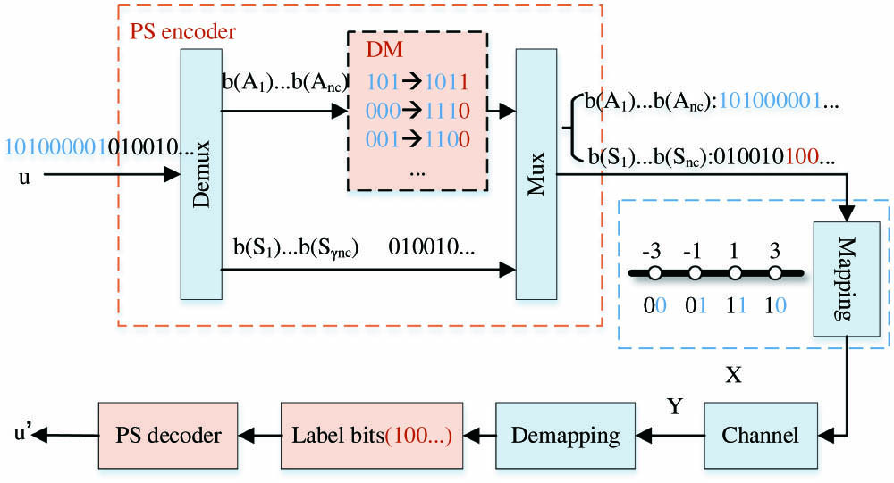
Figure 1 shows the block diagram of the probabilistic shaping implementation based on the proposed ELA method. Considering the codebook size and the convenience of presentation, we take three-symbol coding as an example.
Sign up for Chinese Optics Letters TOC. Get the latest issue of Chinese Optics Letters delivered right to you!Sign up now
![]()
Figure 1.Block diagram of PS structure based on the proposed ELA method.
Since there is one amplitude bit for each PAM-4 symbol, a three-symbol group has three amplitude bits. The uniform bit sequence is first divided into the sign bits [] and the amplitude bits [], respectively, as shown by black numbers and blue numbers in Fig. 1. In order to realize the bilateral MB distribution, the amplitude bits of symbols are grouped and launched into the DM. Here, a redundant label bit is introduced for each three-amplitude bit, as shown by red numbers in Fig. 1. For the label bits, “0” denotes an inversion operation to yield an -symbol group with a lower energy level, and “1” indicates a no operation status. The inversion rule depends on the energy levels and will be discussed later in detail. By assigning the symbols with lower energy levels to replace the original sequence, the PS signal is generated. Following the operations of amplitude and sign multiplexing, symbol mapping, channel transmitting, and symbol de-mapping, the inverse DM operation is implemented with label bits generated at the transmitter.
In the scheme, the label bits as additional sign bits are transmitted, and, in order to keep the uniform distribution of sign bits, we invert the last half of the label bits before symbol mapping, and then perform the inverse operation at the receiver. We define the DM rate as the ratio of the number of input bits to the number of output bits of the DM. With an additional bit per symbols, the DM rate can be calculated as
For a given DM rate , the fraction is described as
Next, the method of energy-level assignment will be presented in detail. We use the Gray code for PAM-4 mapping, where “0” and “1” as sign bits represent “−” and “+”, and “0” and “1” as amplitude bits correspond to “3” and “1”, respectively. As shown in Fig. 1, the amplitude bits are divided into 3 bit groups before implementing DM. Thus, there are permutations and combinations, as shown in the first row of Table 1. The energy of each combination is pre-calculated by
| Amp bits | 000 | 001 | 010 | 011 | 100 | 101 | 110 | 111 |
| Energy | 27 | 19 | 19 | 11 | 19 | 11 | 11 | 3 |
Table 1. Energy of Each Combination for Three-Symbol ELA
![]()
Figure 2.Three-symbol ELA implementation process.
Meanwhile, in the three-amplitude bit combinations with energy E1 to E4, the probabilities of “0” are 1, 2/3, 1/3, and 0, respectively. Probabilities of “0” and “1” can be calculated with encoded amplitude bits of P1 to P4 distributions according to different probabilities of various energy levels,
According to Eqs. (5) and (6), probability distributions of “0” and “1” in P1 can be calculated. Figure 3 shows the PS-PAM-4 signals with four different probability distributions (P1 to P4) based on the three-symbol ELA method. With similar three-symbol encoding, the CAP method can only generate the PS-PAM signal with the P4 distribution. Further, the method can be extended to any -symbol () achieving more distributions with lower redundancy, and probability distributions of “0” and “1” can be expressed as
![]()
Figure 3.Four probability distributed PAM-4 signals based on three-symbol ELA. (a) P1, (b) P2, (c) P3, and (d) P4.
Normalized generalized mutual information (NGMI) is used as the most robust post-forward-error-correction (FEC) bit error rate (BER) prediction[
![]()
Figure 4.NGMI curves of uniform and PS PAM-4 signals over AWGN.
3. Complexity
CCDM is a symbol-level matcher using arithmetic coding, which requires a large number of multipliers in implementation. For every 1 bit input, an interval scaling is performed. For every one-symbol output, a probability update is performed, which is in essence multiplication or division. However, ELA is a bit-level matcher by building an LUT. The complexity of the required circuitry is dominated by the number of stored bits in the LUT, and, for -symbol encoding, bits are required. Complex operations such as integer addition or multiplication are not required in the coding process.
4. Experimental Setup and Results
Figure 5 shows the point to point experimental setup of 25 Gbaud IM/DD PAM-4 for intra-data-center networks. At the transmitter, pseudo-random binary sequence (PRBS) is first launched into the PS encoder, and the PS-PAM-4 data is achieved by bit-to-symbol mapping. Then, the symbol sequence is up-sampled to two samples-per-symbol (sps), and applied with a root-raised cosine (RRC) finite impulse response (FIR) filter with a roll-off factor of 0.4 for pulse shaping to mitigate the signal degradation caused by the limited bandwidth of the transmitter. The filtered and S21 compensated data is loaded into an arbitrary waveform generator (AWG), whose S21 parameter’s curve is inserted, as shown by Fig. 5(a). The 3 dB bandwidth of the AWG is approximately 11 GHz. The end-to-end channel response curves with/without S21 compensation are shown in Fig. 5(b). Meanwhile, a pseudo-noise (PN) sequence is appended for signal synchronization at the receiver. After that, the electrical PAM-4 signal from the AWG is modulated into a continuous wave (CW) laser at 1550.112 nm by a single-drive Mach–Zehnder modulator (MZM). The output power of the modulated optical PAM-4 signal is about 5.7 dBm. After transmission over 2 km SSMF, a variable optical attenuator (VOA) and an erbium-doped fiber amplifier (EDFA) are used to control the noise level for BER measurement. Another VOA is used to control the optical signal power into a 10 GHz photodetector (PD). The received electrical signal is sampled by a real-time oscilloscope (RTO). The received data is first processed by the synchronization algorithm. Afterwards, the discrete digital signal passes through a matched RRC FIR filter and is re-sampled to one sps. Then, the equalization algorithm is utilized to restore the PS-PAM-4 signal. Finally, the de-mapping and PS decoding operation are implemented, and the BER is calculated.
![]()
Figure 5.Experimental setup of 25 Gbaud PAM-4 system. (a) Measured S21 parameter of the AWG; (b) measured end-to-end channel response with/without S21 compensation.
In this work, a 25 Gbaud PAM-4 signal is transmitted over the system of approximately 10 GHz bandwidth. The received signal contains the desired signal and the pre-cursor/post-cursor ISI. Hence, we employ an FFE with a structure, as shown in Fig. 6, which consists of horizontally arranged T-delay units and tap weighting units with coefficients and, thus,
![]()
Figure 6.Structure diagram of FFE.
Figure 7 shows the measured BER curves of the uniform PAM-4 signal, CCDM-PAM-4 signal, and the four PS-PAM-4 signals. The inset is the complementary cumulative distribution function (CCDF) curve, which is mainly used to describe the peak-to-average power ratio (PAPR) of the signal. In this work, a 25 Gbaud PAM-4 signal is transmitted, and the IR of the PS signal can be expressed as in Ref. [4]:
![]()
Figure 7.Measured BER curves for 25 Gbaud uniform and PS-PAM-4 signals. The inset shows the CCDF curves for different distributions.
![]()
Figure 8.Eye diagrams of PS-PAM-4 signals with various probability distributions (−20 dBm): (a) P1, (b) P2, (c) P3, and (d) P4.
5. Conclusion
In this work, we propose an ELA DM method, which can generate multi-distributed PS-PAM-4 signals through energy-level allocation of amplitude bits. We successfully demonstrated the 2 km SSMF transmission of 25 Gbaud multi-distributed PS-PAM-4 signals in an approximately 10 GHz bandwidth system with a low-complexity linear equalization.
References
[1] G. Liu, L. Zhang, T. Zuo, Q. Zhang. IM/DD transmission techniques for emerging 5G fronthaul, DCI, and metro applications. J. Lightwave Technol., 36, 560(2018).
[2] A. Raza, K. Zhong, S. Ghafoor, S. Iqbal, M. Adeel, S. Habib, M. F. U. Butt, C. Lu. SER estimation method for 56 GBaud PAM-4 transmission system. Chin. Opt. Lett., 16, 040604(2018).
[3] D. Zhou, D. Lu, S. Liang, L. Zhao, W. Wang. Transmission of 20 Gb/s PAM-4 signal over 20 km optical fiber using a directly modulated tunable DBR laser. Chin. Opt. Lett., 16, 091401(2018).
[4] G. Böcherer, F. Steiner, P. Schulte. Bandwidth efficient and rate-matched low-density parity-check coded modulation. IEEE Trans. Commun., 63, 4651(2015).
[5] T. A. Eriksson, M. Chagnon, F. Buchali, K. Schuh, S. ten Brink, L. Schmalen. 56 Gbaud probabilistically shaped PAM8 for data center interconnects. European Conference on Optical Communication(2017).
[6] Z. He, T. Bo, H. Kim. Probabilistically shaped coded modulation for IM/DD system. Opt. Express, 27, 12126(2019).
[7] T. Wiegart, F. Da Ros, M. P. Yankov, F. Steiner, S. Gaiarin, R. D. Wesel. Probabilistically shaped 4-PAM for short-reach IM/DD links with a peak power constraint. J. Lightwave Technol., 39, 400(2021).
[8] T. Yoshida, M. Karlsson, E. Agrell. Hierarchical distribution matching for probabilistically shaped coded modulation. J. Lightwave Technol., 37, 1579(2019).
[9] T. V. Ramabadran. A coding scheme for m-out-of-n codes. IEEE Trans. Commun., 38, 1156(1990).
[10] P. Schulte, G. Böcherer. Constant composition distribution matching. IEEE Trans. Inf. Theory, 62, 430(2016).
[11] Y. Sha, M. Gao, M. Liu, C. Zhang, W. Chen, Y. Yan. IM/DD probabilistically shaped 64-QAM OFDM-PON transmission assisted by selective-mapping and flexible systematic polar code. Opt. Commun., 490, 126912(2021).
[12] F. Kschischang, S. Pasupathy. Optimal nonuniform signaling for Gaussian channels. IEEE Trans. Inf. Theory, 39, 913(1993).
[13] J. Cho, S. Chandrasekhar, R. Dar, P. J. Winzer. Low-complexity shaping for enhanced nonlinearity tolerance. European Conference on Optical Communication(2016).
[14] J. Cho, L. Schmalen, P. J. Winzer. Normalized generalized mutual information as a forward error correction threshold for probabilistically shaped QAM. European Conference on Optical Communication(2017).

Set citation alerts for the article
Please enter your email address
© Copyright 2018-2021 | Chinese Laser Press. All Rights Reserved 沪ICP备15018463号-20