
Gongqing Li, Xiaofeng Duan, Yongqing Huang, Kai Liu, Xiaomin Ren. Flat transmitted serrated-phase high-contrast-index subwavelength grating beam splitter[J]. Chinese Optics Letters, 2020, 18(11): 110504
- Chinese Optics Letters
- Vol. 18, Issue 11, 110504 (2020)
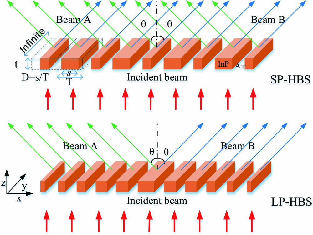
Fig. 1. Schematic diagram of the SP-HBS and LP-HBS. The grating comprises simple dielectric bars with high refractive index, surrounded by a low-index medium, herein, InP and air. T, HCG period;
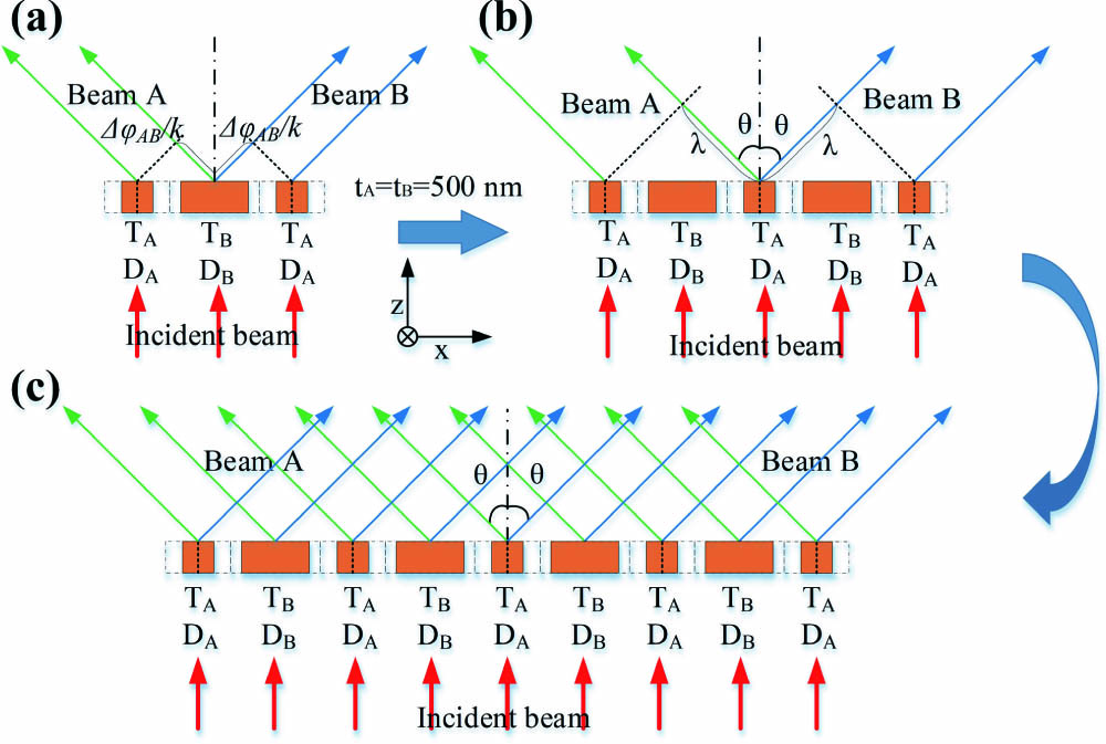
Fig. 2. Schematic diagrams of designing an SP-HBS: (a) a basic grating unit, A-B-A; (b) the periodical extending of basic grating units; (c) a formed SP-HBS.
Fig. 3. Designed grating bars of SP-HBS and LP-HBS distributed on the X axis and their geometric structural parameters: (a) and (b) periods; (c) and (d) duty cycles.
Fig. 4. Transmissivity distributions and phase distributions of the grating bars used in SP-HBS and LP-HBS: (a) and (b) transmissivity distributions; (c) and (d) phase distributions.
Fig. 5. Simulation results of SP-HBS and LP-HBS for the normal incidence of a 1.55 μm TM-polarization Gaussian plane wave: (a) and (b) the electric-field intensity distributions, (d) and (e) the results by measuring the cut lines at
Fig. 6. Simulation results of the SP-HBSs whose
Fig. 7. Simulation results of SP-HBS for the small-angle (

Set citation alerts for the article
Please enter your email address
© Copyright 2018-2021 | Chinese Laser Press. All Rights Reserved 沪ICP备15018463号-20