Abstract
We proposed a method to form a flat transmitted serrated-phase (SP) high-contrast-index subwavelength grating (HCG) beam splitter (HBS) for all dielectric materials, which is to alternately arrange two kinds of grating bars with a phase difference of . Compared to the typical linear-phase (LP) HBS, which consists of two symmetrical deflecting gratings, the SP-HBS is extensible in size, and can achieve excellent splitting ability regardless of normal incidence or small-angle oblique incidence with large deflection angles, higher diffraction efficiency, lower energy loss, and higher tolerance of fabrication accuracy. Furthermore, the incident light can be split in half at any part of the SP-HBS, and the output beams of light maintain the original shape. In this Letter, we designed an SP-HBS with a 44.8° deflection angle and a 90.28% transmissivity.As is well-known, the beam splitter (BS) is one of the most important optical devices in optical systems and the crucial part of most interferometers, such as optical information processing, optical computing, holography, and metrology[1–11]. Nowadays, with the rise of micro-nano structures based on various materials, various optical properties could be achieved by designing different micro-nano structural components, such as high-reflection, high-transmission, deflection, polarization, focusing, and, of course, beam splitting.
The planar dielectric high-contrast-index subwavelength grating (HCG)[12–16] is the emerging geometrical optical micro-nano structure in recent years, which is famous for its excellent ability of light control. The HCG with a periodical form could be made into a reflector, a transmitting mirror with high diffraction efficiency[13–15], or even a wonderful resonator with a high quality factor (Q)[16]. If the grating bars of an HCG are arranged to form a specific phase shift plane, the HCG with non-periodic structure can control the deflection[17,18], splitting[8,9,19], and focusing[20] of the light beam at the same time with high transmissivity or reflectivity. All of these extraordinary features of an HCG are significant for the integration and application with optoelectronic devices in the field of optoelectronics and optical communications[13–15,19]. Naturally, many functional BSs are designed on the basis of gratings and used in different optical domains[8,9,19,21–25].
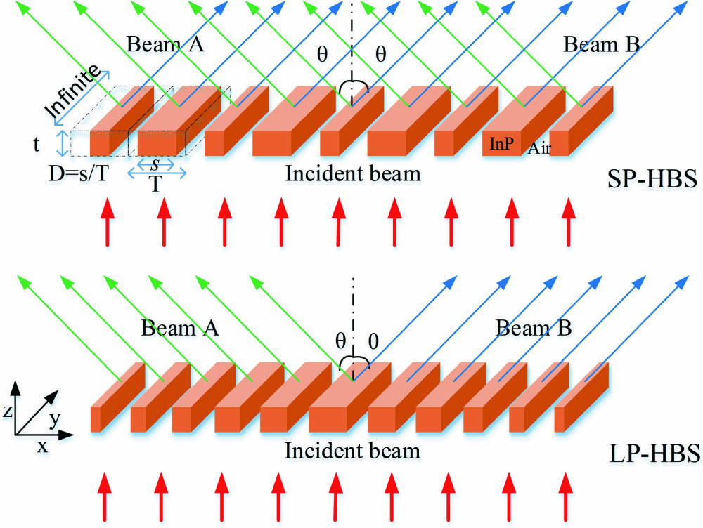
A BS is an optical device that splits a beam of light into two beams with two certain angles. The wave fronts of the two lights propagate in different directions after passing through the BS. Thus, a BS should reform the wave front of the incident light into two different transmitted planes. As illustrated in Fig. 1, for the linear-phase (LP) HCG BS (HBS), its two transmitted planes are formed by two symmetrical deflection gratings[19], and this is a typical beam-splitting structure based on a planar grating. But, here, we proposed another improved beam-splitting structure based on HCG, the transmitted serrated-phase (SP) HBS. As is well-known, the LP-HBS suffers from whether the incident light is aligned at the center of it, and its splitting ability is affected by the complicated deflection-phase plane. In Refs. [15,16], due to the deviation of the deflection-phase plane, the deflection gratings designed suffered from the deviation of the deflection angle and diffraction efficiency compared to the designed value. Thus, for high deflection quality, not only the deviation of phase plane between the designed value and ideal value should be decreased, but also high fabrication accuracy is needed. Fortunately, the SP-HBS can not only overcome these disadvantages, but also possess some advantages that LP-HBS does not have.
Sign up for Chinese Optics Letters TOC. Get the latest issue of Chinese Optics Letters delivered right to you!Sign up now

Figure 1.Schematic diagram of the SP-HBS and LP-HBS. The grating comprises simple dielectric bars with high refractive index, surrounded by a low-index medium, herein, InP and air. T, HCG period; , grating bar width; D, HCG duty cycle, ; , HCG thickness.
With respect to one-dimensional (1D, changes in one dimension) gratings, at the surface-normal incidence of a certain polarized light, because of the large index contrast and subwavelength dimensions, every grating bar with specific thickness, period, and duty cycle has the corresponding diffraction efficiency and phase, and only the zeroth diffraction order exists[15]. Any two side-by-side grating bars will deflect the incident light at an angle that relates to the phase difference between themselves. If we set two kinds of grating bars as the form of “A-B-A,” it is obtained that a simplest HBS will split the incident light into two beams with two symmetric deflection angles. Next, we extend this tiny BS periodically as a form of “A-B-A-B-A…,” so the incident light will be separated into two groups of deflection lights. One group of lights is deflected by the grating bars of “A-B,” and the other group is deflected by the grating bars of “B-A.” If the phase difference between two adjacent light beams in every group at the propagation direction is , an equal phase plane will be formed at the propagation direction. It means that the light beams in every group will constitute one beam of light propagating along the deflection angle. Finally, we obtained an SP-HBS based on an ultra-simple HCG structure.
Herein, the incident lights are 1.55 μm TM-polarization Gaussian plane waves, and their full width at half-maximum (FWHM) is marked in the figures. The grating is made up of indium phosphide (InP) and air, and the refractive index of InP is 3.167. As is shown in Fig. 2, we made a basic grating unit, which consists of grating bar A () and grating bar B (). () are the period, duty cycle, and thickness of the grating bar A, and () are the period, duty cycle, and thickness of grating bar B. The phase difference between the grating bar A and grating bar B is , which is equal to . The phase differences between two adjacent bars A or B are both in the propagation directions of beam A and beam B. Its deflection angle is
Figure 2.Schematic diagrams of designing an SP-HBS: (a) a basic grating unit, A-B-A; (b) the periodical extending of basic grating units; (c) a formed SP-HBS.
According to the method above, we designed and simulated an SP-HBS and an LP-HBS for comparison. Firstly, we calculated numerous grating bars with various periods and duty cycles to get the relevant transmissivity and phase shift by using the rigorous coupled wave analysis (RCWA) method[26,27]. Then, for constituting an SP-HBS, we found grating bars A (1.1 μm, 0.216, 0.5 μm) and B (1.1 μm, 0.764, 0.5 μm), the transmissivities and phase shifts of them are (91.03%, ) and (90.32%, ), respectively, and their theoretical deflection angles are 44.8°. For the design of the LP-HBS, an LP-HBS is made up of two symmetrical deflection gratings, and the design method of a deflection grating is well-known[17,18]. We designed a deflection grating with a 45° deflection angle and mapped it symmetrically to an LP-HBS. In Fig. 3, we gave the geometric parameters of SP-HBS and LP-HBS. Figures 3(a) and 3(b) show the distributions of periods of grating bars of SP-HBS and LP-HBS on the X axis, respectively, and Figs. 3(c) and 3(d) show their duty cycles, respectively. From Fig. 3, the geometric structure of LP-HBS is more complicated than that of SP-HBS.
Figure 3.Designed grating bars of SP-HBS and LP-HBS distributed on the X axis and their geometric structural parameters: (a) and (b) periods; (c) and (d) duty cycles.
In Fig. 4, we show the transmissivity and phase of the grating bars used by SP-HBS and LP-HBS. As seen in Figs. 4(a) and 4(b), grating bars A and B of SP-HBS have almost the same transmissivity and are both very high; in contrast, the transmissivity of the grating bars in LP-HBS differs greatly, and some of them are only about 60%. The low transmissivity of individual grating bars will affect the overall transmissivity of the BS, and the large difference in transmissivity between the grating bars will also affect the beam deflection angle. Figures 4(c) and 4(d) show the designed phase profiles of SP-HBS and LP-HBS. SP-HBS consists of two types of grating bars with phase difference arranged alternately; its phase plane looks like a sawtooth, so it is named “serrated-phase HCG beam splitter”. From the figure, the equivalent phase plane formed by extending the phase plane of SP-HBS is in good agreement with the ideal deflection-phase plane. However, due to the requirements of the LP plane and high transmissivity, LP-HBS has to choose some grating bars with low transmissivity or phase deviation (or both), which causes offset between the actual phase plane and the theoretically ideal phase plane. It also means that there is a deviation of the actual beam-splitting angle and a decrease in transmissivity. Furthermore, due to the 1D structure and linear deflection-phase plane, SP-HBS and LP-HBS are both sensitive to the polarization of incident light, because the phase of a grating bar is dependent on the polarization of incident light.
Figure 4.Transmissivity distributions and phase distributions of the grating bars used in SP-HBS and LP-HBS: (a) and (b) transmissivity distributions; (c) and (d) phase distributions.
SP-HBS and LP-HBS are simulated by using the COMSOL Multiphysics, which is based on the finite element method (FEM)[28]. The simulation results are depicted in Fig. 5. From Fig. 5(a), we can clearly note that the incident light is split into two beams well and maintains the Gaussian shape. Then, we cut Fig. 5(a) at , 20 μm, and 40 μm to get three cut lines to measure the deflection angle and transmissivity numerically; see Fig. 5(d). The deflection angle is 44.8°, consistent with the theoretical value. We calculated the line integration of the transmitted power at the cut line and found that the total transmissivity is 90.28%, which is extremely near to the transmissivities of grating bars. We also mentioned this in Fig. 4(a). Figure 5(c) shows the splitting effect of an SP-HBS with a 9.9 μm width. The transition from the near- to the far-field occurs around . The splitting effect of the SP-HBS is very good regardless of the far-field and near-field. In Fig. 5(f), the electric-field intensities of cut lines of Fig. 5(c) at , 60 μm, and 90 μm are measured. The deflection beams maintain the Gaussian shape when propagating away from the near- to the far-field, but exhibit strong scattering, which meets the Huygens–Fresnel diffraction principle. But, in the application domain of the SP-HBS, the size is usually much larger than the width we simulated here, which means that the SP-HBS usually operates at the near-field. From these results, we can know that the SP-HBS can achieve excellent beam-splitting ability. Besides, the total transmissivity of the SP-HBS is very close to the transmissivity of the grating bar, which means that the diffraction efficiency of the SP-HBS will be very high when grating bars A and B that we selected possess high diffraction efficiencies (near one); in other words, the energy loss of SP-HBS will be very low.
Figure 5.Simulation results of SP-HBS and LP-HBS for the normal incidence of a 1.55 μm TM-polarization Gaussian plane wave: (a) and (b) the electric-field intensity distributions, (d) and (e) the results by measuring the cut lines at , 20 μm, and 40 μm in (a) and (b), with (a) and (d) for SP-HBS and (b) and (e) for the LP-HBS; the FWHM of incident light is 20 μm. (c) is the splitting effect of an SP-HBS with 9.9 μm width when the incident light () propagates from the near- to far-field, and (f) is the measurement results by cutting (c) at , 60 μm, and 90 μm.
As a comparison, we did the same operation to the LP-HBS. See in Fig. 5(b), although LP-HBS also achieved the beam-splitting effect, a central leakage beam and some sub-beams in other directions appeared, and the Gaussian shape was torn into two parts. From Fig. 5(e), the transmissivity is only 79.11%, which is much lower than that of SP-HBS. The deflection angle is 43.6°, deviating 1.4° from the designed value, which meets the deviation of the phase plane shown in Fig. 4(d). In summary, SP-HBS has a simpler structure, higher transmissivity, better beam-splitting effect, and a more accurate deflection-phase plane than LP-HBS and can maintain the original shape of incident light.
We also investigated how the SP-HBS performs when the phase difference between grating bars A and B is not enough to . Actually, the problem of phase difference corresponds to the problem of fabrication accuracy. Due to the fabrication accuracy, the geometric parameters of the fabricated grating bars must be in error compared to the design values, which means that the actual phase shift will differ from the design value. Hence, we designed five gratings whose phase differences are , , , , and , respectively. We set all periods of all the gratings as 1.1 μm. The simulation results of the five gratings are shown in Fig. 6 together with the SP-HBS. All gratings can still split the light into two beams, where the measured deflection angles are 44.22°, 43.95°, 44.63°, 44.91°, and 44.47°, respectively. Because the periods of grating bars of these gratings are same as the SP-HBS, the deflection angles should be the same. According to the results, compared to the 44.8°, the variation of the deflection angles is very small and could be considered a measurement error. However, as the decreases, the light leaking out in the vertical direction gradually increases, which we can call energy loss. Especially in Figs. 6(e) and 6(f), as to the cases of and , the vertical leakage beam has become the main transmitted beam. In a word, SP-HBS can still split the light at the designed deflection angle though the phase difference between grating bars A and B is less than . But, there is a vertical leakage beam, which is affected by the phase difference. As seen in Fig. 6(d), for the case of , the leakage beam is still not very strong, which will not affect the splitting function. So, it means that the phase difference between grating bars A and B can tolerate high errors; it also means that the grating bars we select can tolerate high errors in geometric structure. So, when fabricating an SP-HBS, the geometric size of the grating does not need to be strictly in accordance with the designed value. In other words, the SP-HBS has a high tolerance of fabrication accuracy. However, due to the complicated deflection-phase plane of the LP-HBS, many grating bars with high transmissivity and specific phase shift are required to form the designed steering phase plane. But, it is very difficult to obtain all suitable grating bars with high transmissivity and specific phase shift simultaneously. Sometimes, the grating bars we used only satisfied the phase requirement, and the transmissivity was sacrificed to a lower value. This caused lower diffraction efficiency, high energy loss, and deteriorated splitting beams. Because of its strict phase requirement, the LP-HBS needs to be fabricated accurately or the splitting effect will be affected. In summary, the performance of the LP-HBS with a complex phase plane will be affected by each grating bar, which makes it difficult to guarantee high performance and requires high fabrication accuracy.
Figure 6.Simulation results of the SP-HBSs whose are (a) , (b) , (c) , (d) , (e) , and (f) . Insets are the normalized electric-field intensity of the cut line at .
We designed the SP-HBS for the plane wave with normal incidence, and we also studied the behavior for the small-angle () oblique incidence. Owing to the large index contrast and subwavelength dimension of the grating bar, the diffraction efficiency and phase shift will not change much when the grating is at small-angle oblique incidence. By combining the above conclusions, a small deviation to of does not affect the splitting effect much. So, for the small-angle oblique incidence, the SP-HBS can still split the light well. But, because the small incident angle causes the difference of optical paths between beams A and B, it will change the deflection angles of them. The deflection angles arewhere is the oblique incident angle. In Fig. 7, we show the splitting effect of SP-HBS for the oblique incident angle . The deflection angles of beams A and B are 52.3° and 38.1°, respectively, which coincide with the theoretical values very well.
Figure 7.Simulation results of SP-HBS for the small-angle () oblique incidence of a 1.55 μm TM-polarization Gaussian (FWHM = 5 μm) plane wave. The deflection angles of beams A and B are 52.3° and 38.1°, respectively.
SP-HBS is very simple to design; only two kinds of grating bars are required to be arranged alternatively. Thus, we can expand the size of SP-HBS at will. Unfortunately, the size of LP-HBS is limited because its phase plane is hard to expand casually. Furthermore, due to the periodical structure of SP-HBS, the incident light can be split at any position, but, for the LP-HBS, the incident light can only be split at the center.
In conclusion, we proposed a method to form an improved transmitted BS based on HCG. By using this method, we designed an SP-HBS with a 44.8° deflection angle and a 90.28% transmissivity. Regardless of the normal incidence or the small-angle oblique incidence, the SP-HBS can achieve excellent beam-splitting ability, high diffraction efficiency, low energy loss, and high tolerance of fabrication accuracy. Compared to the LP-HBS, due to its simple geometric structure, the SP-HBS is much easier to design with no limits in size. The incident light could be split at any position of an SP-HBS. Furthermore, the SP-HBS can maintain the original shape of the incident light after splitting. The SP-HBS with these extraordinary features is significant for applications in integrated optoelectronics, optical interferometers, or some other optical systems.
References
[1] J. Xing, S. Jin, P. Hu, G. Xia, M. Hu. J. Opt. Soc. Am. A, 34, 344(2017).
[2] M. Papaioannou, E. Plum, N. I. Zheludev. ACS Photon., 4, 217(2017).
[3] C. Li, D. Dai. Opt. Lett., 42, 4243(2017).
[4] G. K. Kostyuk, R. A. Zakoldaev, V. V. Koval, M. M. Sergeev, V. S. Rymkevich. Opt. Laser Eng., 92, 63(2017).
[5] M. Lai, C. Huang. Sci. Rep., 7, 4531(2017).
[6] T. Lunghi, F. Doutre, A. P. Rambu, M. Bellec, M. P. De Micheli, A. M. Apetrei, O. Alibart, N. Belabas, S. Tascu, S. Tanzilli. Opt. Express, 26, 27058(2018).
[7] T. R. Harvey, F. S. Yasin, J. J. Chess, J. S. Pierce, R. M. S. dos Reis, V. B. Özdöl, P. Ercius, J. Ciston, W. Feng, N. A. Kotov, B. J. McMorran, C. Ophus. Phys. Rev. Appl., 10, 061001(2018).
[8] J. Yang, Z. Zhou. Opt. Commun., 285, 1494(2012).
[9] S. Fahr, T. Clausnitzer, E.-B. Kley, A. Tünnermann. Appl. Opt., 46, 6092(2007).
[10] R. Borghi, G. Cincotti, M. Santarsiero. J. Opt. Soc. Am. A, 17, 63(2000).
[11] C. Xiang, C. Zhou, W. Jia, J. Wu. Chin. Opt. Lett., 16, 070501(2018).
[12] C. F. R. Mateus, M. C. Y. Huang, Y. Deng, A. R. Neureuther, C. J. Chang-Hasnain. IEEE Photon. Tech. Lett, 16, 518(2004).
[13] M. C. Y. Huang, Y. Zhou, C. J. Chang-Hasnain. Nat. Photon., 1, 119(2007).
[14] C. J. Chang-Hasnain. Semicond. Sci. Tech., 26, 014043(2011).
[15] C. J. Chang-Hasnain, W. Yang. Adv. Opt. Photon., 4, 379(2012).
[16] J. Hu, X. Liu, J. Zhao, J. Zou. Chin. Opt. Lett., 15, 030502(2017).
[17] L. Carletti, R. Malureanu, J. Mørk, I. S. Chung. Opt. Express, 19, 23567(2011).
[18] C. Ma, Y. Huang, X. Duan, X. Ren. Chin. Opt. Lett., 12, 120501(2014).
[19] J. Fei, Y. Huang, W. Fang, T. Liu, X. Duan, K. Liu, X. Ren. Opt. Express, 25, 21726(2017).
[20] D. Fattal, J. Li, Z. Peng, M. Fiorentino, R. G. Beausoleil. Nat. Photon., 4, 466(2010).
[21] J. Feng, Z. Zhou. Opt. Lett., 32, 1662(2007).
[22] H. Zhao, D. Yuan, H. Ming. Opt. Laser Technol., 43, 599(2011).
[23] B. Wang, L. Chen, L. Lei, J. Zhou. Opt. Commun., 296, 149(2013).
[24] Y. Xu, J. Xiao. Opt. Lett., 41, 773(2016).
[25] J. Zhang, X. Zhang. Micro Nano Lett., 12, 767(2017).
[26] N. M. Lyndin, O. Parriaux, A. V. Tishchenko. J. Opt. Soc. Am. A, 24, 3781(2007).
[27] V. Karagodsky, C. J. Chang-Hasnain. Opt. Express, 20, 10888(2012).
[28] O. C. Zienkiewicz, R. L. Taylor. The Finite Element Method(2005).