• High Power Laser Science and Engineering
  • Vol. 10, Issue 1, 010000e1 (2022)
Tao Liu*, Kaiqing Zhang, Zheng Qi, Si Chen, Chao Feng, Haixiao Deng, Bo Liu, and Dong Wang
Author Affiliations
  • Shanghai Advanced Research Institute, Chinese Academy of Sciences, Shanghai201210, China
  • show less
    DOI: 10.1017/hpl.2021.55 Cite this Article Set citation alerts
    Tao Liu, Kaiqing Zhang, Zheng Qi, Si Chen, Chao Feng, Haixiao Deng, Bo Liu, Dong Wang. Matching-based two-color X-ray free-electron laser generation utilizing laser–plasma accelerated electron beam[J]. High Power Laser Science and Engineering, 2022, 10(1): 010000e1 Copy Citation Text show less
    Schematic of the proposed scheme for the LPA-based two-color FEL generation. Two quadrupole sections are adopted for matching the bunch tail and head, respectively. The first chicane is used to induce the time-dependent matching, and the second chicane is for time separation of the two-color pulses. Two planar undulator sections are arranged for the two-color FEL generation individually.
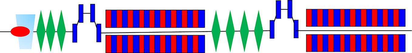
    Fig. 1. Schematic of the proposed scheme for the LPA-based two-color FEL generation. Two quadrupole sections are adopted for matching the bunch tail and head, respectively. The first chicane is used to induce the time-dependent matching, and the second chicane is for time separation of the two-color pulses. Two planar undulator sections are arranged for the two-color FEL generation individually.
    Phase space distributions as a function of time downstream of the triplet and decompression chicane. The time-dependent transverse phase spaces show the visible variation along the bunch especially in x and x′ due to the controlled chromaticity effect. Bunch head is on the left.
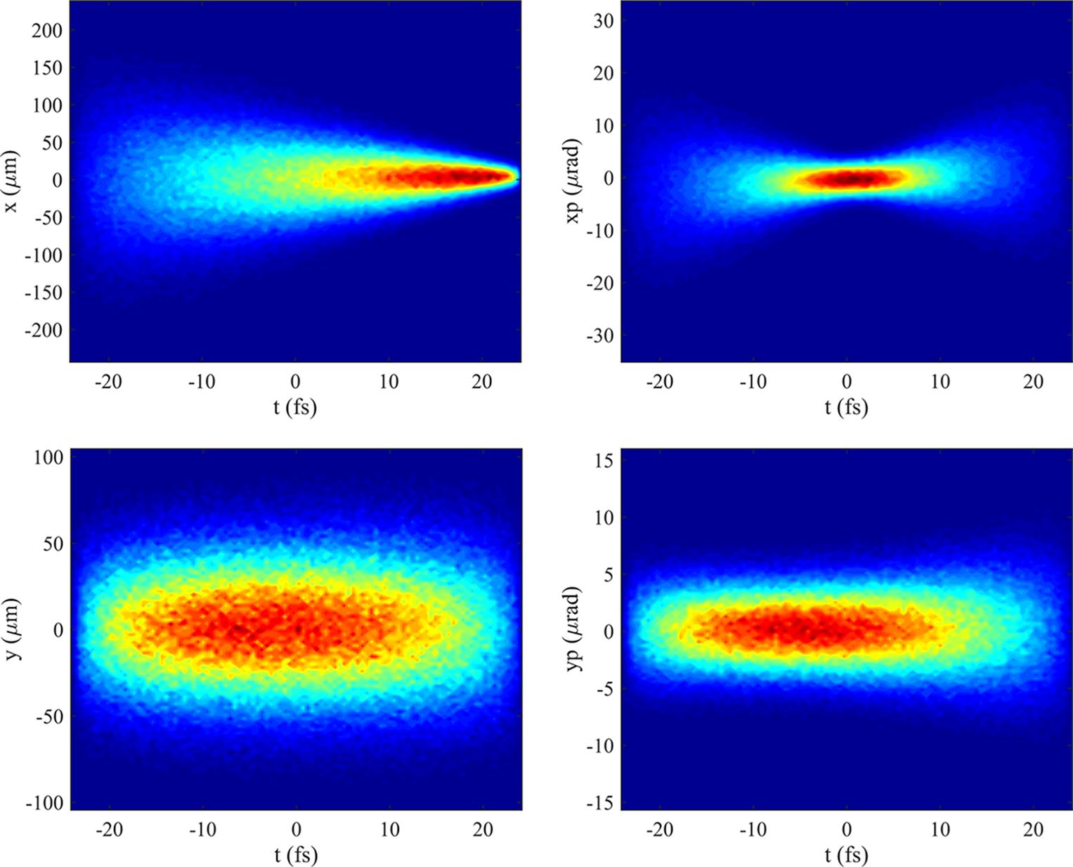
    Fig. 2. Phase space distributions as a function of time downstream of the triplet and decompression chicane. The time-dependent transverse phase spaces show the visible variation along the bunch especially in x and x due to the controlled chromaticity effect. Bunch head is on the left.
    Layout of the lattice design and evolutions of beta functions with different beam energy deviations along the transport line. Left: Energy is 1.29 GeV at the bunch tail. Right: Energy is 1.31 GeV at the bunch head. Two undulator sections are located at the 5–20 m range and 25–40 m range, respectively.
    Fig. 3. Layout of the lattice design and evolutions of beta functions with different beam energy deviations along the transport line. Left: Energy is 1.29  GeV at the bunch tail. Right: Energy is 1.31 GeV at the bunch head. Two undulator sections are located at the 5–20 m range and 25–40 m range, respectively.
    Sliced parameters of the LPA beam at the entrance of the first undulator section.
    Fig. 4. Sliced parameters of the LPA beam at the entrance of the first undulator section.
    Two-color FEL pulses are generated individually. Blue line and red line are corresponding to the bunch tail part and head part, respectively. Exponential gains are shown in the top subgraph. The middle two present the temporal profiles and the frequency profiles of the two-color pulses. The bottom subgraphs present the maximum bunching factors and increased energy spreads. The head part is on the right.
    Fig. 5. Two-color FEL pulses are generated individually. Blue line and red line are corresponding to the bunch tail part and head part, respectively. Exponential gains are shown in the top subgraph. The middle two present the temporal profiles and the frequency profiles of the two-color pulses. The bottom subgraphs present the maximum bunching factors and increased energy spreads. The head part is on the right.
    FEL power profile: the time structure (left) and the spectrum (right) of the two-color FEL pulse at the end of the scheme. The head part is on the right.
    Fig. 6. FEL power profile: the time structure (left) and the spectrum (right) of the two-color FEL pulse at the end of the scheme. The head part is on the right.
    Longitudinal phase spaces at the exit of the first undulator section and the second undulator section, respectively. Energy chirp distributions are not drawn here. The head part is on the left.
    Fig. 7. Longitudinal phase spaces at the exit of the first undulator section and the second undulator section, respectively. Energy chirp distributions are not drawn here. The head part is on the left.
    Time separations of the two colors. Time separations in the six subgraphs are 14 fs, –10 fs, –100 fs, –200 fs, –600 fs and –1 ps, respectively.
    Fig. 8. Time separations of the two colors. Time separations in the six subgraphs are 14 fs, –10 fs, –100 fs, –200 fs, –600 fs and –1 ps, respectively.
    ParametersValuesUnits
    Beam energy1.3GeV
    Emittance0.2mm·mrad
    Beam size (r.m.s.)0.8μm
    Divergence (r.m.s.)0.1mrad
    Peak current8kA
    Bunch length (r.m.s.)1μm
    Energy spread (r.m.s.)1%
    Table 1. Main parameters of an LPA beam.
    Tao Liu, Kaiqing Zhang, Zheng Qi, Si Chen, Chao Feng, Haixiao Deng, Bo Liu, Dong Wang. Matching-based two-color X-ray free-electron laser generation utilizing laser–plasma accelerated electron beam[J]. High Power Laser Science and Engineering, 2022, 10(1): 010000e1
    Download Citation