
Bing Lü, Wentao Zhang, Wenzhu Huang, Fang Li. Random Bragg-grating-based wavelength-tunable random fiber laser with a full-open cavity[J]. Chinese Optics Letters, 2021, 19(9): 091203
- Chinese Optics Letters
- Vol. 19, Issue 9, 091203 (2021)
Abstract
1. Introduction
Tunable fiber lasers with single-longitudinal-mode operation are of considerable interest for many applications, such as optical precision metrology, high-resolution spectroscopy, high-precision sensors, and communication systems[
Most wavelength-tunable (WT)-RFLs use single-mode fibers (SMFs) to provide backward Rayleigh scattering (RS) and use Raman gain or Brillouin gain to support random lasing. However, the backward RS coefficient and the gain coefficient of SMFs are relatively lower. WT-RFLs based on SMFs are not typically compact with high threshold due to using tens of kilometers SMF to provide efficient gain and random feedback[
The WT-RFL based on an RBGA has been realized by using a tunable optical band-pass filter (TOBPF)[
Sign up for Chinese Optics Letters TOC. Get the latest issue of Chinese Optics Letters delivered right to you!Sign up now
In this Letter, we propose a compact and low-threshold WT-RFL with a full-open cavity formed by two RBGAs. A transfer matrix model including spectral regimes for both RBGAs and is introduced to demonstrate the function mechanism and tunable characteristics of the WT-RFL output spectra and obtain the relevant grating fabricating parameters. The simulation results show that the with narrow bandwidth can be used as a filter to select/control lasing wavelengths precisely. The full-open-cavity design provides a several hundred picometers (pm) wavelength tuning range, which mainly depends on the 3 dB bandwidth of two RBGAs. The compact structure of the proposed WT-RFL is less sensitive to environmental turbulence, which reduces the fluctuation of laser power and wavelength.
2. Theoretical Analysis and Numerical Results
The configuration of the proposed WT-RFL is shown in Fig. 1. To analyze and predict the characteristics of the WT-RFL output spectra, we analyze the reflection spectra of the RBGA[
![]()
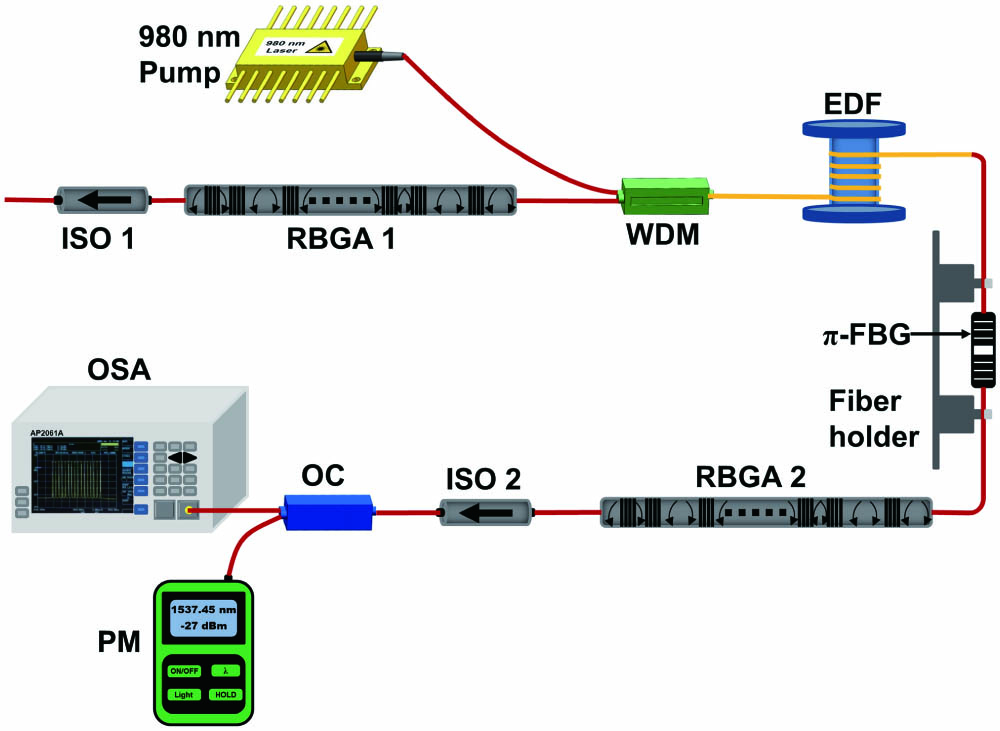
Figure 1.Schematic of the experimental setup for the WT-RFL. OC, optical coupler.
, , and are the transfer matrix of the FBG, SMF, and RBGA, respectively, and can be expressed by Eqs. (1)–(3):
The complex reflection coefficient of the RBGA, , can be expressed by Eq. (4):
is the transfer matrix of and can be expressed by Eq. (5):
The transmission coefficient of the , , can be expressed by Eq. (6):
The simulation results are shown in Fig. 2. Figure 2(a) is calculated by Eqs. (1)–(4), where many random intervals in the RBGA cause multiple randomly scattered lights to overlap each other, resulting in narrow chaotic peaks in the reflection bandwidth. Random longitudinal modes of RFL are determined by these random intervals and are superimposed on each other to form a continuous longitudinal mode structure, which is different from a traditional fixed cavity structure. Figure 2(b) is calculated by Eqs. (5) and (6). The transmission window of the is narrow, and the loss outside the transmission window is flat. The result shows that the can be used as a transmission filter. The emission spectrum of the RFL is mainly determined by the filter and gain of the EDF. The longitudinal modes under the transmission filter will change as the gain changes. These longitudinal modes are amplified multiple times, and only the longitudinal mode near the center wavelength of the will overcome the cavity loss and become the lasing mode. As shown in Fig. 2(c), the wavelength of the lasing spectrum corresponds to the transmission center wavelength of the , which proves that the embedded in the proposed WT-RFL can select the lasing wavelength by its narrow transmission window, setting the transmission wavelength of the in Fig. 2(c) to 1537.424 nm, 1537.446 nm, 1537.470 nm, 1537.492 nm, and 1537.516 nm, respectively. Figure 2(d) shows that there is no wavelength difference at the selected wavelengths. Numerical simulation results further demonstrate the wavelength selecting and tuning characteristics of the .
![]()
Figure 2.Numerical simulation spectra of the RBGA and
3. Experiments and Results
Two RBGAs form a compact full-open-cavity structure, which shortens the length of the random resonant cavity and reduces the lasing threshold due to its strong random feedback efficiency. Two RBGAs are fabricated in a common SMF (Corning-28), where 30 FBGs are fabricated by 248 nm ultraviolet (UV) exposure and the phase mask method. The length, center wavelength, and reflectivity of each FBG are controlled to 3 mm, 1537.45 nm, and ; meanwhile, the separation between two neighboring FBGs is chosen randomly in the range of 3–8 cm. The total length of two RBGAs is about 168 cm. The is between two translation stage, and can be adjusted by applying axial strain. The narrow transmission window of the plays a critical role in selecting and tuning the output wavelength of the WT-RFL effectively. A 4-m-long EDF is pumped by a 980 nm laser with a maximum power of 250 mW through a 980/1550 nm wavelength division multiplexer (WDM). The partial reflection spectrum of matching RBGA1 resonates and amplifies in a random resonant cavity, and RBGA2 forces the back propagation light to run in one direction. The isolator (ISO) prevents the external reflected light from entering the feedback cavity. The laser spectrum and output power are monitored by an optical spectrum analyzer (OSA, AP2061A, APEX) and an optical power meter (PM, Acterna), respectively.
We use an OSA with a resolution of 1.12 pm to measure the reflection spectra and the transmission spectra of two RBGAs. Figure 3(a) shows that RBGA1 has a 3 dB bandwidth of 0.393 nm and a center wavelength of 1537.454 nm, and Fig. 3(b) shows that RBGA2 has a 3 dB bandwidth of 0.352 nm and a center wavelength of 1537.458 nm. The transmittance () of two RBGAs is and , respectively. The light localization effect occurs in the wavelength range of the grating regions and ignores the portion without gratings. Random lasing can be generated as long as the length of localization is much shorter than that of the random medium. The length of each RBGA, , is about 168 cm. The localization length, , can be estimated from [
![]()
Figure 3.Reflection spectra and transmission spectra of (a) RBGA1 and (b) RBGA2.
The is also fabricated by the same method as the two RBGAs. In addition, a baffle is added to block a part of the UV laser, so that a small part of the blocked fiber is not exposed to the UV laser, resulting in phase mutation[
![]()
Figure 4.(a) Reflection and transmission spectra of two RBGAs and π-FBG. (b) The wavelength of π-FBG as a function of the strain.
When the WT-RFL operates at a stable single wavelength of 1537.452 nm, we measure the change of output power as a function of the injected pump power. As shown in Fig. 5, the pump threshold is , which is very low for the full-open-cavity WT-RFLs[
![]()
Figure 5.Output power versus different pump power.
We fix the lasing wavelength at about 1537.452 nm and measure the lasing spectra from the output port at different pump powers ranging from 22 mW to 220 mW. As shown in Fig. 6, single-wavelength lasing is caused by photon localization in the two RBGAs when the pump power is above the threshold. As the pump power increases, the output wavelength does not vary with the pump power, and the center wavelength of the laser remains at 1537.452 nm, which indicates that the proposed WT-RFL has good wavelength stability. Besides, the 3 dB linewidth of the lasing spectrum is expected to be much less than 1 pm at the maximum pump power of 220 mW.
![]()
Figure 6.Output spectra measured under different pump power at 1537.452 nm.
To control and select different lasing wavelengths, the is axially fixed on a manual stage and a piezo stage (PI, P-841) with an interval of 25 cm, as indicated in Fig. 1. Then, we control the lasing spectra by applying axial strain to the filter. The spectral evolution under different strains with the pump power of 180 mW is shown in Fig. 7. The strain, which is applied to the , is also increased by 18 µε each time, and lasing wavelengths at 1537.424 nm, 1537.446 nm, 1537.470 nm, 1537.492 nm, and 1537.516 nm are obtained when the strains are 36 µε, 54 µε, 72 µε, 90 µε, and 108 µε, respectively. The lasing wavelength is almost consistent with the wavelength of the transmission spectrum in Fig. 3(b) with the same strain applied. This is because adjusts the transmission loss of random cavities, effectively reduces the amount of resonant modes, and locks the lasing wavelength under the narrow transmission window, which ensures tunable and relatively stable laser spectra. The wavelength tuning range can be improved by adjusting the wavelength of the and two RBGAs simultaneously or increasing the 3 dB reflection bandwidth of two RBGAs. The experimental results in Fig. 7 are similar to the simulated output spectra in Fig. 2(d). Compared with the simulated lasing wavelength, there is no difference at different selected wavelengths. Numerical simulation can further demonstrate the wavelength locking and tuning characteristics of the . However, the peak power in Fig. 7 is different from the simulated results of Fig. 2(d), because we make the vertical axis normalized and do not consider the effect of pump light, signal light, and spontaneous emission light in the EDF.
![]()
Figure 7.Laser spectra at different measured wavelengths.
It is also important to check the long-term stability of the WT-RFL. Figure 8 shows the fluctuation of lasing wavelengths and peak power of the WT-RFL within 16 min of three selected wavelengths when the pump power is 180 mW. We can record every 2 min for each case and obtain stable output at different wavelengths due to the short random distributed feedback fiber and high random feedback efficiency of two RBGAs. The peak-power fluctuations recorded in Fig. 8 are 0.42 dB, 0.55 dB, and 0.36 dB, respectively; meanwhile, we observe that the maximum variation of wavelength is less 1 pm for three selected lasing wavelengths. These experimental results indicate that we propose a compact WT-RFL, which has stable single-wavelength operation at our selected wavelengths.
![]()
Figure 8.Wavelength and peak-power fluctuations of selected wavelengths versus time.
4. Conclusion
In conclusion, we have proposed and demonstrated a compact and stable WT-RFL with a full-open cavity formed by two RBGAs. The design of two RBGAs combined with a transmission filter further decreases the fluctuations of laser power and wavelength. The low lasing threshold of 22 mW and the maximum peak-power fluctuation of 0.55 dB are obtained. The tuning range of the center wavelength is several hundred pm. Above the lasing threshold, it can stably launch a single-longitudinal-mode coherent lasing operation at different selected wavelengths, which provides a new option for high-resolution optical sensing and coherent communication, as well as having significant meaning for research of tunable random emission.
References
[1] N. J. C. Libatique, L. Wang, R. K. Jain. Single-longitudinal-mode tunable WDM-channel-selectable fiber laser. Opt. Express, 10, 1503(2002).
[2] S. K. Turitsyn, S. A. Babin, A. E. El-Taher, P. Harper, D. V. Churkin, S. I. Kablukov, J. D. Ania-Castañón, V. Karalekas, E. V. Podivilov. Random distributed feedback fibre laser. Nat. Photon., 4, 231(2010).
[3] S. A. Babin, A. E. El-Taher, P. Harper, E. V. Podivilov, S. K. Turitsyn. Tunable random fiber laser. Phys. Rev. A, 84, 021805(2011).
[4] Y. Y. Zhu, W. L. Zhang, Y. Jiang. Tunable multi-wavelength fiber laser based on random Rayleigh back-scattering. IEEE Photon. Technol. Lett., 25, 1559(2013).
[5] P. Huang, X. Shu, Z. Zhang. Multi-wavelength random fiber laser with switchable wavelength interval. Opt. Express, 28, 28695(2020).
[6] S. Miao, W. Zhang, Y. Song. Random Bragg-gratings-based narrow linewidth random fiber laser with a π-phase-shifted FBG. Chin. Opt. Lett., 17, 071403(2019).
[7] M. Gagné, R. Kashyap. Random fiber Bragg grating Raman fiber laser. Opt. Lett., 39, 2758(2014).
[8] M. I. Skvortsov, S. R. Abdullina, A. A. Vlasov, E. A. Zlobina, I. A. Lobach, V. S. Terentyev, S. A. Babin. FBG array-based random distributed feedback Raman fibre laser. Quantum Electron., 47, 696(2017).
[9] S. R. Abdullina, M. I. Skvortsov, A. A. Vlasov, E. V. Podivilov, S. A. Babin. Coherent Raman lasing in a short polarization-maintaining fiber with a random fiber Bragg grating array. Laser Phys. Lett., 16, 105001(2019).
[10] Z. Guo, J. Song, Y. Liu, Z. Liu, P. Shum, X. Dong. Randomly spaced chirped grating-based random fiber laser. Appl. Phys. B, 124, 48(2018).
[11] Y. Li, P. Lu, F. Baset, Z. Ou, J. Song, A. Alshehri, V. R. Bhardwaj, X. Bao. Narrow linewidth low frequency noise Er-doped fiber ring laser based on femtosecond laser induced random feedback. Appl. Phys. Lett., 105, 101105(2014).
[12] M. Gagné, R. Kashyap. Demonstration of a 3 mW threshold Er-doped random fiber laser based on a unique fiber Bragg grating. Opt. Express, 17, 19067(2009).
[13] Y. Li, P. Lu, X. Bao, Z. Ou. Random spaced index modulation for a narrow linewidth tunable fiber laser with low intensity noise. Opt. Lett., 39, 2294(2014).
[14] J. Deng, M. Han, Z. Xu, Y. Du, X. Shu. Stable and low-threshold random fiber laser via Anderson localization. Opt. Express, 27, 12987(2019).
[15] W. L. Zhang, R. Ma, C. H. Tang, Y. J. Rao, X. P. Zeng, Z. J. Yang, Z. N. Wang, Y. Gong, Y. S. Wang. All optical mode controllable Er-doped random fiber laser with distributed Bragg gratings. Opt. Lett., 40, 3181(2015).
[16] W. L. Zhang, Y. B. Song, X. P. Zeng, R. Ma, Z. J. Yang, Y. J. Rao. Temperature-controlled mode selection of Er-doped random fiber laser with disordered Bragg gratings. Photon. Res., 4, 102(2016).
[17] B. Hu, W. Zhang, R. Ma, J. Guo, A. Ludwig, Y. Rao. Wavelength locking of Er-doped random fiber laser. Laser Phys. Lett., 16, 055102(2019).
[18] O. Shapira, B. Fischer. Localization of light in a random-grating array in a single-mode fiber. J. Opt. Soc. Am. B, 22, 2542(2005).
[19] M. Yamada, K. Sakuda. Analysis of almost-periodic distributed feedback slab waveguides via a fundamental matrix approach. Appl. Opt., 26, 3474(1987).
[20] V. Milner, A. Z. Genack. Photon localization laser: low-threshold lasing in a random amplifying layered medium via wave localization. Phys. Rev. Lett., 94, 073901(2005).
[21] J. T. Kringlebotn, J. L. Archambault, L. Reekie, D. N. Payne. Er3+:Yb3+-codoped fiber distributed-feedback laser. Opt. Lett., 19, 2103(1994).
[22] N. H. Z. Abidin, L. K. Yao, M. H. A. Bakar, N. Tamchek, M. A. Mahdi. Open cavity controllable dual-wavelength hybrid Raman-erbium random fiber laser. IEEE Photon. J., 11, 1503208(2019).

Set citation alerts for the article
Please enter your email address
© Copyright 2018-2021 | Chinese Laser Press. All Rights Reserved 沪ICP备15018463号-20