Abstract
A time-resolved high-power laser photometer, which measures the real-time variations of transmission, internal reflection, and scattering simultaneously with picosecond time resolution, was developed to investigate the material response sequence during high-power nanosecond laser irradiation in thick fused silica. It was found that the transient transmission decreased sharply, accompanied by an increase in internal reflection at the rising edge of the laser pulse. The transient transmission recovered, while laser damage did not occur, but it did not recover if the scattering increased, indicating the occurrence of laser damage. The reason for the sharp decrease of transmission and the relationship between the transmission drop and laser damage were discussed.The power of a laser system was limited by the laser damage resistance of optical components, especially the fused silica irradiated by the ultraviolet laser[1,2]. During the high-power nanosecond laser irradiation in thick fused silica, various physics processes, such as multi-photon ionization, self-focusing, and stimulated Brillouin scattering (SBS), occurred and coupled with others[3]. Multi-photon ionization helped electron excite from the valence band to the conduction band. Accompanied with impact ionization, the density of free electrons increased sharply[4]. Self-focusing occurred while the natural divergence due to diffraction was compensated by the focusing due to a higher refractive index in the middle of the beam. The Gaussian profile beam will self-focus to a tiny diameter, usually making a filamentary damage in fused silica[5,6]. SBS was driven by the electrostriction of the bulk medium, which tends to become denser in the regions of high optical density. The transmitted light could be converted to Stokes wave scattering mainly in the backward direction, which often initiates front surface damage in silica glasses due to SBS[7,8].
As the above physical processes were generated in a nanosecond or even shorter timescale[9], the transient material responses were difficult to obtain, and the detailed response sequence during high-power nanosecond laser irradiation in the bulk of fused silica is still unclear. However, understanding these transient modifications is of importance for attractive applications such as inertial confinement fusion[1] and laser micromachining[10].
In order to understand the transient material responses, some dynamic detection techniques were developed, which can be roughly divided into two categories: high-speed sampling technique and pump–probe technique. The high-speed sampling technique directly detects changes in the optical properties of the material with high temporal resolutions. Carr et al., using the time-resolved spectra, indicated that the localized temperature can be as high as , and the peak pressure is of the order of 10 GPa during a laser-induced bulk damage event in fused silica[11]. Recently, Lamaignère et al. characterized the SBS in thick fused silica with high temporal resolution and investigated the surface damage due to SBS[12]. The pump–probe technique usually captures transient images at a specific moment during laser irradiation by adjusting the time delay between the pump and probe light. Negres et al. used this technique to study the damage growth following the irradiation in thick fused silica, which proved that the growth of cracks continues until tens of nanoseconds after the irradiation[13]. DeMange et al. investigated the early response of fused silica, which indicated that the damage occurred at the rising edge of the pulse, and the electronic excitation process emerges firstly during the damage event[14]. Recently, Shen et al. investigated the filamentary damage formation phases in fused silica based on this technique, and the coupling between Kerr-induced self-focusing and SBS is applied to interpret the damage formation[15].
Sign up for Chinese Optics Letters TOC. Get the latest issue of Chinese Optics Letters delivered right to you!Sign up now
In this study, based on the high-speed sampling technique, a time-resolved photometer, which enables a simultaneous measurement of the transient transmission, reflection, and scattering with picosecond time resolution, was developed. Using this time-resolved photometer, the material response sequence during the entire nanosecond laser irradiation in fused silica was investigated. The results revealed that the transmission decreased first at the rising edge of the pulse, accompanied by an increase of the internal reflection, owing to the SBS. While there was no macroscopic damage, the transmission would recover after the peak of the pulse. While the damage occurred, following the occurrence of the reflection, the scattering increased immediately, and the transmission did not recover. The intense SBS process, leading to high localized pressure, was believed to assist the plasma formation and nonlinear self-focusing during the damage event.
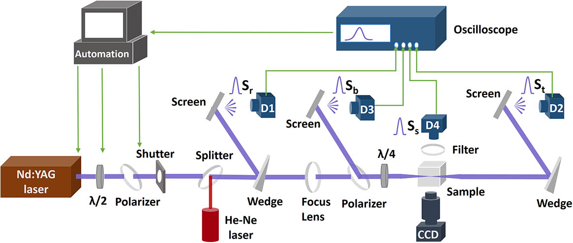
The schematic of the time-resolved photometer is shown in Fig. 1. The -switched neodymium yttrium aluminum garnet (Nd:YAG) laser produces a single longitude mode pulse at a wavelength of 355 nm, with an approximately Gaussian temporal profile, and full width at half-maximum of the intensity of . Varied attenuation was provided with a rotating half-wave plate and thin-film polarizer.

Figure 1.Schematic of the time-resolved photometer: , half-wave plate; , quarter-wave plate; D1/D2/D3/D4, photodiode detectors.
Before entering the sample, the laser beam was split by a wedge plate; the reflected beam was scattered and detected using a fast photodiode detector D1. The detected signal was defined as the reference signal . The transmitted beam was focused into the bulk of fused silica through a focus lens with a focal length of 300 mm. The beam profile in the focus region in air was approximately Gaussian with a radius (at ) of . The size of the fused silica sample was , all of its surfaces were polished, and the beam was focused at from each surface. After passing through the sample, the beam was split by another wedge plate, and the reflected beam was scattered and detected using a fast photodiode detector D2. The detected signal was defined as a transmitted signal .
An optical isolator, consisting of a polarizer and quarter-wave plate in front of the sample, was used to acquire the internal reflection or back-scattering. The incident angle of the laser beam on the sample was to avoid the influence of surface reflection. The p-polarized light passing through the quarter-wave plate, whose optical axis was oriented at 45° with respect to the polarization of the incident light, formed a circularly polarized light. If there was reflected light, the reflected light passing through the quarter-wave plate was converted again to an -polarized light. The -polarized light through the polarizing plate would be reflected to the scattering screen and detected by the photodiode detector D3. The detected signal was defined as a reflected signal .
In addition, the scattered signal was recorded by a photodiode detector D4, orthogonal to the direction of laser propagation. A bandpass filter centered at 355 nm (bandwidth ) was applied to ensure that only the light scattered from the nanosecond excitation pulse was detected. The bulk damage was detected in real-time by the increase of the scattering signal . Moreover, a continuous He–Ne laser was employed to illuminate the sample; the macroscopic damage after the high-power laser pulse irradiation was also observed by the scattering image of the He–Ne laser using a charge-coupled device.
It is worth noting that all of the signals were scattered prior to their detection. This reflected the variation of the entire laser beam and avoided beam focusing into the detector, which could easily lead to detector damage. The diffusing screen was made of a polytetrafluoroethylene (PTFE) plate, which would not emit luminescence pumped by a 355 nm laser. The signals detected with D1, D2, D3, and D4 were captured with an oscilloscope (Tektronix DPO7040 C) operating at a bandwidth of 4 GHz and a sampling rate of 25 GS/s, i.e., sample signals were recorded every 40 ps. It is noted that in order to obtain the variation sequence of these signals, the influence of optical path difference and electronic timing difference among these signals was calibrated using the sub-threshold pulses.
Using the above setup, the time-resolved reference signal , transmitted signal , reflected signal , and scattered signal during nanosecond laser irradiation were simultaneously measured. The transmission was obtained by ; as a correction factor, 0.92 was the transmission of the fused silica at normal incidence. The reflection and scattering ratios were obtained by and , respectively; these are relative values, but useful in revealing changes in reflection and scattering. For each irradiation pulse, a fresh sample location is used to avoid an accumulated damage.
Figure 2 presents the signal variations and corresponding variations of the optical properties during a nanosecond irradiation, while the laser intensity was . As shown in Fig. 2(a), the transmitted signal decreased significantly at the rising edge of the pulse, and the reflected signal increased almost at the same time. As shown in Fig. 2(b), the transmission decreased by approximately 40% in accompanied with the increase of the reflection. However, after the peak of the pulse, the transmission began to increase and reached the original value at the end of the pulse, and the reflection gradually decreased. In addition, no significant variation in the scattering was observed, indicating there was no damage.
Figure 2.While the laser intensity was , (a) the time-resolved signal variations and (b) the variations of the optical properties during the irradiation.
While the laser intensity was up to , as shown in Fig. 3(a), the transmitted signal also decreased suddenly at the rising edge of the pulse. But, it began to decrease earlier than that in Fig. 2(a), and the reflected signal was more intense than that in Fig. 2(a). As shown in Fig. 3(b), with the increase of the reflection, the transmission decreased by approximately 60% in , which is a more rapid decrease than that in Fig. 2(b). After the peak of the pulse, the transmission also exhibited a recovery trend, and no significant variation in the scattering was observed.
Figure 3.While the laser intensity was , (a) the time-resolved signal variations and (b) the variations of the optical properties during the irradiation.
As the laser intensity increased to , an earlier moment of decline in transmission and increase in reflection was observed in Fig. 4(a), compared with that in Fig. 3(a). However, the scattered signal increased immediately following the reduction of transmitted signal. As shown in Fig. 4(b), following the increase of the reflection, a spike in the scattering ratio appeared, indicating the occurrence of macroscopic damage. The scattering ratio continued to increase, and another obvious spike was observed during the irradiation. The transmittance did not recover after the peak of pulse, but remained low during the irradiation.
Figure 4.While the laser intensity was , (a) the time-resolved signal variations and (b) the variations of the optical properties during the irradiation.
During the damage event in Fig. 4, a white-light emission, a characteristic of the plasma[16], was observed. The spectral detection demonstrated that the wavelength range of the broad emission is , as shown in Fig. 5(a). Figure 5(b) shows the time-integrated plasma emission image (integration time is 500 μs, including the plasma formation) acquired by blocking the 355 nm laser. The damage was a deformed filamentary region and a head surrounded by compacted materials and cracks, as shown in Fig. 5(c).
Figure 5.(a) Broadband emission spectrum associated with the damaged fused silica. (b) Plasma emission image integrated for 500 μs. (c) The optical microscopy image of the damage site.
As described above, the material response sequence during the irradiation of a high-power nanosecond laser in fused silica can be summarized as follows: (1) a significant decrease in the transmission emerged first at the rising edge of the pulse, accompanied with the increase of the internal reflection; (2) while there was no damage, the transmission would recover with the transient power decreasing; (3) while the damage occurred, following the increase of the reflection, the transmission did not recover with an increase of the scattering, and the scattering ratio kept on increasing during the irradiation. The underlying physics processes were discussed to interpret the material response sequence.
In order to ascertain the cause of decline in transmittance, the reflected and transmitted energies at different laser intensities were measured. As shown in Fig. 6(a), the energy loss in fused silica, calculated by subtracting the surface loss () and transmitted energy from the incident energy, is almost equal to the reflected energy. Therefore, the reduction in the transmission is mainly caused by the increase of the reflection. With the increase of the intensity, the reflectivity, defined as the ratio of the reflected energy to the incident energy, increased nonlinearly and could reach , as shown in Fig. 6(b).
Figure 6.(a) Reflected energy and energy loss [with subtracted surface loss () and transmitted energy from the incident energy] as a function of the laser intensity. (b) Reflectivity as a function of the laser intensity.
There are two potential physical explanations for the sharp decrease of transmission, accompanied by the internal reflection. One is the formation of plasma. When the electronic density is over-critical, the plasma formed, and it would reflect the beam[17]. However, no plasma emission was captured while laser damage did not occur. Therefore, the internal reflection did not result from the plasma. The other one is due to the SBS in the fused silica. As we know, the nanosecond laser pulses can excite an acoustic wave, and a Stokes wave scatters in the backward direction, mainly in silica glasses[7]. The SBS reflectivity increased nonlinearly with the increase of the incident energy, and it could exceed 90%[18], which was consistent with the reflection characteristics we measured. In addition, our statistical time-resolved measurements revealed that the critical power for the increase of reflection was , as shown in Fig. 7. Smith et al. measured the SBS threshold of silica at the wavelength of 1064 nm as [4]. Considering that the threshold is approximately proportional to the wavelength, the SBS threshold at 355 nm would be , which is close to our measurement results. Thus, it is reasonable to attribute the observed reflection to SBS.
Figure 7.Threshold power for the increase of reflection at different laser intensities.
During high-power laser irradiation in thick fused silica, while the transient laser power exceeded the threshold, the transmission significantly decreased first, owing to the increase of SBS. The SBS resulted from the electrostriction of the fused silica, and the electrostrictive pressure is proportional to the electric field[19]. Thus, after the peak of the pulse, with the decrease of the incident electric field, the SBS would decrease, leading to the recovery of the transmission, as shown in Figs. 2 and 3. However, when the pulse intensity was sufficiently high, the transmission did not exhibit a recovery tendency, accompanied by the growth of the laser damage.
As shown in Fig. 4, after the occurrence of SBS, the scattering increased immediately, indicating that SBS assisted the damage formation. Considering the filamentary damage morphology [Fig. 5(c)] and the peak power in Fig. 4 was , which has reached the critical power for self-focusing ([4]), the self-focusing effect should play an important role during this damage event. In addition, a plasma emission [Figs. 5(a) and 5(b)] occurred with the generation of laser damage. The observed intense SBS could couple with these two nonlinear processes to assist the damage formation. First, the electrostrictive effect, leading to intense SBS in the fused silica, would result in an increase of the nonlinear refractive index[20]. With a higher nonlinear refractive index, the self-focusing dynamics were amplified, contributing to the filamentary damage formation. Secondly, according to the Keldysh theory, the photoionization rate is inversely proportional to the band gap of the material[21]. During the intense SBS process, the fused silica in the presence of a high localized pressure undergoes a volume deformation or strain, which could lead to band gap reduction[22]. With the strain-induced reduction in the band gap, the ionization rate was amplified, which could assist the formation of the plasma, causing the damage formation.
After the generation of the damage, as shown in Fig. 4, the scattering ratio continued to increase, although the incident transient laser intensity decreased, which indicated that the damage kept on growing during the irradiation. Indeed, the growth of the cracks was observed up to following the laser-induced breakdown in the fused silica[14]. Many optical defects were produced during the laser-induced breakdown, such as oxygen deficient defects and non-bridging oxygen hole centers[23]. The absorbing and mechanically modified material can reignite the damage process, leading to damage growth. In addition, there were two spikes in the scattering ratio. The first spike should correspond to the sudden generation of the damage, and the second spike likely resulted from the significant growth of the head of the filamentary damage during the irradiation[15].
In summary, a time-resolved photometer, which can simultaneously measure transient transmission, reflection, and scattering, was developed to investigate the material response sequence during a high-power nanosecond irradiation into thick fused silica. Our results revealed that the transmission significantly decreased first at the rising edge of the pulse accompanied by the increase of the reflection, mainly owing to the SBS. While the damage did not occur, the transmission would recover after the peak of the pulse. However, with higher intensity laser irradiation, after the occurrence of a more intense SBS, a spike in the scattering would appear immediately, revealing the generation of damage, and the transmission would not recover. The damage continued to grow during the irradiation, which is confirmed by the increase in the scattering ratio. The intense SBS could assist the plasma formation and self-focusing, contributing to the damage formation.
References
[1] P. A. Baisden, L. J. Atherton, R. A. Hawley, T. A. Land. Fusion Sci. Technol., 69, 295(2016).
[2] G. Hu, Y. Zhao, X. Liu, D. Li, Q. Xiao, K. Yi, J. Shao. Opt. Lett., 38, 2632(2013).
[3] M. Veinhard, O. Bonville, S. Bouillet, E. Bordenave, R. Courchinoux, R. Parreault, J. Y. Natoli, L. Lamaignère. J. Appl. Phys., 124, 163106(2018).
[4] A. V. Smith, B. T. Do. Appl. Opt., 47, 4812(2008).
[5] M. J. Soileau, W. E. Williams, N. Mansour, E. W. V. Stryland. Opt. Eng., 28, 281133(1989).
[6] R. Khrapko, C. Lai, J. Casey, W. A. Wood, N. F. Borrelli. Appl. Phys. Lett., 105, 244110(2014).
[7] S. Mauger, L. Bergé, S. Skupin. Phys. Rev. A, 83, 063829(2011).
[8] L. Sun, R. Ni, H. Xia, T. Shao, J. Huang, X. Ye, X. Jiang, L. Cao. IEEE Photon. J., 10, 1(2018).
[9] D. von der Linde, K. Sokolowski-Tinten, J. Bialkowski. Appl. Surface Sci., 109, 1(1997).
[10] D. Chu, X. Sun, Y. Hu, X. Dong, K. Yin, Z. Luo, J. Zhou, C. Wang, J. A. Duan. Chin. Opt. Lett., 15, 071403(2017).
[11] C. Carr, H. Radousky, A. Rubenchik, M. Feit, S. G. Demos. Phys. Rev. Lett., 92, 087401(2004).
[12] L. Lamaignère, K. Gaudfrin, T. Donval, J. Natoli, J.-M. Sajer, D. Penninckx, R. Courchinoux, R. Diaz. Opt. Express, 26, 11744(2018).
[13] R. A. Negres, M. D. Feit, S. G. Demos. Opt. Express, 18, 10642(2010).
[14] P. DeMange, R. A. Negres, R. N. Raman, J. D. Colvin, S. G. Demos. Phys. Rev. B, 84, 054118(2011).
[15] C. Shen, M. Chambonneau, X. A. Cheng, Z. Xu, T. Jiang. Appl. Phys. Lett., 107, 111101(2015).
[16] S. C. Jones, P. Braunlich, R. T. Casper, X.-A. Shen, P. Kelly. Opt. Eng., 28, 281039(1989).
[17] K. Nahen, A. Vogel. IEEE J. Sel. Top. Quantum Electron., 2, 861(1996).
[18] Y. Hidetsugu, F. Hisanori, N. Masahiro, Y. Kunio. Jpn. J. Appl. Phys., 38, L521(1999).
[19] R. Y. Chiao, C. H. Townes, B. P. Stoicheff. Phys. Rev. Lett., 12, 592(1964).
[20] A. C. Liu, M. J. F. Digonnet, G. S. Kino. J. Opt. Soc. Am. B, 18, 187(2001).
[21] L. Keldysh. Sov. Phys. JETP, 20, 1307(1965).
[22] E. Gao, B. Xie, Z. Xu. J. Appl. Phys., 119, 014301(2016).
[23] M. Stevens-Kalceff, A. Stesmans, J. Wong. Appl. Phys. Lett., 80, 758(2002).