
Biqiang Jiang, Xiaoming Zhang, Ailun Li, Yueguo Hou, Zhen Hao, Xuetao Gan, Jianlin Zhao. Electrically induced dynamic Fano-like resonance in a graphene-coated fiber grating[J]. Photonics Research, 2022, 10(5): 1238
- Photonics Research
- Vol. 10, Issue 5, 1238 (2022)
Abstract
1. INTRODUCTION
Fano resonance, as a universal phenomenon, arises from the interference of broad and narrow radiation or transmission spectra [1]. In contrast to the symmetric Lorentzian profile, Fano resonance often has a distinctly sharp and asymmetric profile, determined by Fano parameter [2]. As a result, a slight perturbation in the local environment can cause pronounced amplitude and phase changes in the transmission or extinction spectra, enabling Fano resonance to be a powerful tool for many applications in the physical, chemical, and biological sciences [3–6]. To date, the observation and utilization of Fano resonance has also been advanced from quantum systems to photonic structures [3,7–12]. In these photonic schemes, optical whispering-gallery mode microcavities with narrow resonance linewidths have been extensively exploited to couple with tapered fibers or interferometers with broad spectra and then generate Fano-like resonances [13–18]. However, to access resonant modes in these microcavities, tapered or lensed fibers are required via evanescent wave coupling, but have complicated coupling configurations and require rigorous considerations of the coupling gap and phase matching condition. More importantly, only static generation or limited tuning of Fano resonances has been implemented in most photonic schemes.
From the perspective of line shape management or flexibility enhancement of Fano devices, optical fiber structures would be an alternative promising system. Some efforts have been made to achieve the effective tuning of a Fano-like resonance line shape by varying structural parameters or an interaction process between discrete and continuum modes. For instance, changing the microcavity size or coupling distance/position with tapered fibers [14–17,19,20] can be used to adjust the spectral line shapes of Fano-like resonances. Applying mechanical deformation [21], temperature [22,23], refractive index [24], inner gas pressure [6] adjustment, or optical gain [25] on the device can also change the coupling state and tune the Fano resonance line shape. Unfortunately, there is still a challenge in the fast, continuous, and controllable tuning of Fano-like resonance, which determines the flexibility of a Fano device.
In this work, we report the achievement of dynamic tuning of Fano-like resonance in an all-fiber system. To implement that, a graphene-coated fiber Bragg grating (FBG) with two electrodes is inserted into one pathway of a fiber Mach–Zehnder interferometer (MZI). An asymmetric Fano-like line shape at the FBG’s Bragg resonance is formed by controlling the phase shift in either pathway of the MZI. The electrically pumped Joule heating effect of graphene will continuously modify the spectral line shape between a symmetric transmission dip, asymmetric Fano-like, and a transmission peak in the interference valley. The latter is often called an electromagnetically induced transparency (EIT)-like peak [26,27]. When applying a periodically changed voltage on graphene, the Fano parameter can be switched between and , showing a dip or peak of the Fano-like line shape at Bragg resonance wavelength. As a result, the fast and periodical switch of a light signal can be achieved by the filtering of Fano-like resonance, demonstrating an extensive application in optical modulation or switching.
Sign up for Photonics Research TOC. Get the latest issue of Photonics Research delivered right to you!Sign up now
2. THEORETICAL ANALYSIS
Figure 1(a) depicts the schematics of the operation system for the generation and dynamic tuning of Fano-like resonances. An input light from an amplified spontaneous emission (ASE) source or tunable laser (TL) is divided into two pathways via coupler 1 (C1). An FBG is inserted into one pathway of an MZI, and an optical delay line (ODL) is placed into the other pathway to control the initial phase difference between two pathways and free spectrum range (FSR) of the interference spectrum. After that, the two pathways are recombined into the output light via another coupler (C2). The output light can be monitored by an optical spectrum analyzer (OSA) or detected by a photodetector (PD) and an oscilloscope (OSC). To produce an additional phase shift on one pathway of the MZI and observe the dynamic evolution of spectral line shape, few-layer graphene was transferred onto the FBG’s surface, and two gold electrodes were then coated on both sides of the graphene layer. Referring to this arrangement, we first theoretically analyze the generation and tuning characteristics of the Fano-like resonance line shape.
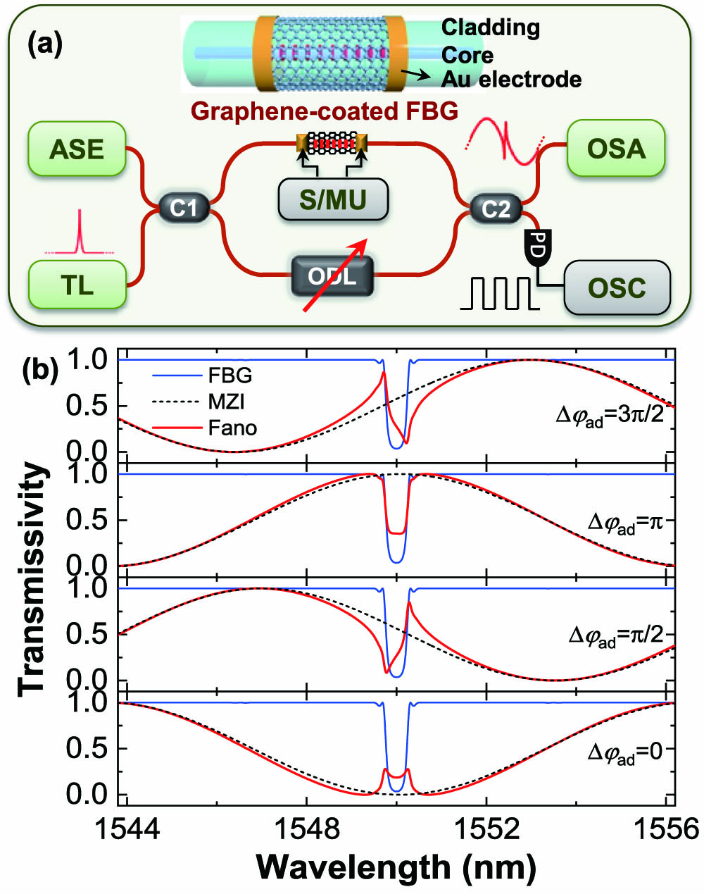
Figure 1.Schematical demonstration of the generation and tuning system of Fano-like resonance. (a) Configuration of an FBG in one arm of an MZI. The inset shows the model of graphene-coated FBG. (b) Theoretical calculations of the spectral line shapes at different phase shifts
When the amplitude transmittivity of the coupler in the pathway with the FBG is , and the intrinsic phase difference accumulated by the two pathways is after adjusting the ODL, the total transmission from the MZI can be determined by [23]
In numerical calculations, the initial phase difference introduced by the ODL, FBG, and the length difference of MZI’s two pathways is set as (corresponding to an optical path difference of ) at the wavelength of 1550 nm for a desired FSR of , and parameters , the maximum reflection of FBG at Bragg wavelength , are selected for a perfect extinction ratio () and sharp Fano-like line shape. Figure 1(b) plots the calculated results at different . By changing from zero to , , , the hybrid spectra of FBG and MZI will be converted among symmetric EIT-like peaks, asymmetric Fano-like profiles, and symmetric transmission dips. When , the Bragg resonance is at the interference valley of the MZI. A dual EIT-like peak (Fano parameter or [3,23]) is clearly observed, indicating that the FBG provides two adjacent discrete states or phase jumps at both sides of the Bragg resonance for Fano-like resonance. When , an asymmetric Fano-like profile with a positive appears at one shoulder of MZI’s interference spectrum. By increasing to , the spectral line shape reverts to the symmetric transmission dip, from the spectral superposition of FBG and MZI. When is further increased to , the spectrum evolves into the asymmetric Fano-like line shape again, but with a negative .
3. EXPERIMENTAL DEMONSTRATION AND DYNAMIC TUNING OF FANO-LIKE RESONANCE
To confirm the above theoretical results, we constructed the experimental system shown in Fig. 1(a). In the experiment, the employed FBG was UV-inscribed in a hydrogenated single mode fiber (SMF) by scanning a phase mask with a frequency-double laser. The grating length and period were 10 mm and , respectively. The grating region was masked by an aluminum foil, and a pair of gold electrodes was deposited onto both sides of the FBG by thermal evaporation deposition. To enhance the adherence of gold electrodes on fibers, a 5 nm thick chromium layer was pre-deposited under the gold layer. Then, the length and thickness of each electrode were 5 mm and 30 nm, respectively. The employed few-layer graphene was grown on a copper foil by chemical vapor deposition. After chemically etching the copper foil, the graphene film was wrapped around the FBG by a wetting transfer technique [28,29]. After that, the device was placed on the heating platform to remove residual moisture and enhance the ohmic contact between the graphene layer and electrodes by thermal annealing.
Figure 2(a) displays the optical microscope image of the surface of the fabricated device, showing a clear edge of the graphene layer and Au electrode. Figure 2(b) gives the scanning electron microscope (SEM) image, and we can observe a relatively uniform graphene layer with only some tiny wrinkles. The graphene-coated FBG is then spliced into one arm of the MZI. From theoretical analysis, the Fano-like resonance is dependent on the relative position of Bragg resonance with respect to the interference spectrum, so the MZI’s FSR will determine the evolution period of the spectral line shape. To clearly observe the evolution of the spectral line shape near the Bragg resonance, a suitable FSR can be controlled by adjusting the ODL. Launched from the ASE source with a broadband light, the transmission spectrum is monitored by the OSA. To produce a continuous phase shift, a precision source/measure unit (S/MU, Keysight B2902A) is used to provide an adjustable voltage and heat the FBG or a local region of the MZI. When the applied voltage is 10 V, we observe a sharply asymmetric Fano-like line shape, as shown in Fig. 2(c). For the MZI, the interference fringes have a good visibility of and a desired FSR of 12.3 nm. For the Fano-like resonance line shape, the maximum ER and SR are 9.0 dB and 69.8 dB/nm, respectively. By changing the voltage on the graphene layer from 0 V to 70 V, we measured the volt–ampere characteristic curve, as shown in Fig. 2(d). The electrical conductivity of the graphene layer on the fiber surface is . The conductivity is dependent on the layer number, size, and transfer homogeneity of graphene, as well as the overlap width with the electrodes, which determines the pump-heating efficiency. Thus the two gold electrodes and graphene can become a uniform electrical micro-heater [30].
![]()
Figure 2.(a) Optical microscope and (b) scanning electron microscope (SEM) images of the graphene-coated FBG with Au electrodes. (c) Transmission spectrum at the applied voltage of 10 V, showing a distinct Fano-like line shape. (d) Volt–ampere characteristic curve of the device.
In the applied voltage of 0–70 V, the electric injection into the graphene layer will yield Joule heating () proportional to the square of current (), , to heat the FBG and local region of MZI’s one arm. Consequently, an additional phase shift from 0 to 2 () will be introduced into the interference arm with the FBG, and the spectral profile gradually and periodically evolves from the dip to sharp Fano-like and EIT-like line shapes, as shown in Fig. 3(a). The detailed spectral evolution at the applied voltage from 0 V to 35 V can be observed in
![]()
Figure 3.(a) Spectral evolution at different voltages of 0 V, 9 V, 13 V, and 17 V (please see the detailed evolution in
By continuously increasing the voltage to 70 V, the above evolution process can be periodically reproduced, and the Fano-like line shapes depend critically on the relative position of Bragg resonance with respect to the interference valley (see
To describe distinct features of the line shape evolution, we plot Fano parameters , ER, and SR of the line shapes in the FBG-MZI spectra. Fano parameter , being a cotangent of the phase shift between the continuum and discrete modes, characterizes the specific asymmetric profile of the Fano-like line shape [3,18]. The detailed can be estimated by fitting it with the analogous Fano formula , where , , , and and are the spectral width and central wavelength of FBG’s Bragg resonance, respectively. The results are shown in the bottom of Fig. 3(b). In the electrical injection, we obtain a periodical cotangent-like function for different , indicating that , and correspond to the symmetric dips, sharply asymmetric Fano-like profiles, and EIT-like peaks, respectively. The cotangent fitting function has a period of , corresponding to a response coefficient of of the phase shift. For the first evolution period, the ERs can be calculated by counting the maximum and minimum around each Fano-like resonance, as shown in Fig. 3(c). The ERs of Fano-like line shapes with near are larger than those of dips and EIT-like peaks, which are determined by the coupling between Bragg resonance and interference modes. The ERs for all line shapes present a sine change with squared current, which is similar to the results from microring resonators [31]. Another important feature of the Fano-like line shape, the SR, is calculated by taking the average slope of the spectral line shape. It is determined by the linewidth of resonance spectra and the difference between maximum and minimum transmissions. The calculated average SR variation is plotted in Fig. 3(d). The transmission dips (or EIT-like peaks) with the symmetric line shape and () have smaller SRs. In contrast, the asymmetric Fano-like lineshapes with have higher SRs. This profile of an asymmetric narrow line therefore allows switching the signal from maximum to minimum transmissions [32,33].
To verify this, we periodically supply the voltage of 9 V and 17 V on the graphene-coated FBG by using the experimental setup shown in Fig. 1(a). The spectral transmission is switched between positive and negative Fano-like line shapes, as shown in Fig. 4(a). A 1550 nm narrow light from the TL as a signal light is modulated by the applied voltage, which enables the electrically induced optical switching effect. When the TL wavelength is equal to the dip (at 9 V) or peak (at 17 V) of the asymmetric Fano-like lineshape, the PD will output a minimum or maximum signal, corresponding to the “off” and “on” states of the signal.
![]()
Figure 4.Observation of electrically induced thermo-optic switching effect. (a) Periodically modulated voltage (top) and switch of reversed Fano-like line shapes (bottom) with applied voltage. (b) Temporal response of optical switching effect.
To examine the optical switching performance, the time response performance of the device was then recorded by applying a square wave and measured with an OSC, as shown in Fig. 4(b). The rise or fall process is related to the switching of the voltage supply at 9 V and 17 V. We measured the time of 0.42 s taken for the signal to change from 10% (90%) to 90% (10%) of the rising (falling) edge, which is normally defined in analog signal processing. The response time is relatively slow for an optical switch, while it is enough for sensing or tuning the dispersion of all-fiber devices. As demonstrated in Ref. [34], the response speed mainly depends on the pump-heating transfer process and then can be further improved by using an FBG in microfiber or ultrathin fiber with a reduced diameter. In addition, the lower switching voltage obtained with a graphene electrode by adjusting the Fano parameter and linewidth would also help to reduce the response time [30].
4. CONCLUSION
The generation and dynamic tuning of Fano-like resonance are theoretically and experimentally demonstrated in an all-fiber system incorporating a graphene-coated FBG into a fiber MZI. The coherent coupling of the discrete Bragg resonance and continuum propagating mode will excite a sharply asymmetric Fano-like resonance line shape. In theory, the evolution of an asymmetric Fano-like profile to symmetric transmission dips and EIT-like peaks can be observed by introducing an additional phase shift to change the relative position of Bragg resonance with respect to the interference spectrum. In experiment, the fast, continuous, controllable tuning of the Fano-like line shape can be achieved by heating the FBG or local region of the MZI, with the help of an electrically induced thermal-optical effect. We also discussed the spectral parameters of , FSR, , ER, and SR of different line shapes. All Fano-related parameters exhibit periodic changes, and the Fano-like line shapes with near have the maximum ER and SR. In addition, we constructed an electrically induced thermo-optic switch with the ER of 9 dB, by using two reversed Fano-like resonances. In comparison with the reported schemes, the well-engineered Fano-like resonance with a controllable line shape enhances the flexibility of a Fano device and holds great promise for applications in optical signal processing, slow-light lasing, and fiber sensing. In addition, the integration of a grating and interferometer also provides a new idea for the generation and modulation of Fano-like resonance in on-chip optical devices.
Acknowledgment
Acknowledgment. We thank the Analytical & Testing Center of NPU for its assistance with the material and device characterizations.
References
[1] M. F. Limonov. Fano resonance for applications. Adv. Opt. Photon., 13, 703-771(2021).
[2] U. Fano. Effects of configuration interaction on intensities and phase shifts. Phys. Rev., 124, 1866-1878(1961).
[3] M. F. Limonov, M. V. Rybin, A. N. Poddubny, Y. S. Kivshar. Fano resonances in photonics. Nat. Photonics, 11, 543-554(2017).
[4] Z. Xu, Y. Luo, Q. Sun, C. Mou, Y. Li, P. P. Shum, D. Liu. Light velocity control in monolithic microfiber bridged ring resonator. Optica, 4, 945-950(2017).
[5] C.-Y. Chao, L. J. Guo. Biochemical sensors based on polymer microrings with sharp asymmetrical resonance. Appl. Phys. Lett., 83, 1527-1529(2003).
[6] S. Zhang, S.-J. Tang, S. Feng, Y.-F. Xiao, W. Cui, X. Wang, W. Sun, J. Ye, P. Han, X. Zhang, Y. Zhang. High-
[7] S. Fan. Sharp asymmetric line shapes in side-coupled waveguide-cavity systems. Appl. Phys. Lett., 80, 908-910(2002).
[8] M. Rahmani, B. Luk’yanchuk, M. Hong. Fano resonance in novel plasmonic nanostructures. Laser Photon. Rev., 7, 329-349(2013).
[9] A. E. Miroshnichenko, S. Flach, Y. S. Kivshar. Fano resonances in nanoscale structures. Rev. Mod. Phys., 82, 2257-2298(2010).
[10] A. Bogdanov, K. Koshelev, P. Kapitanova, M. Rybin, S. Gladyshev, Z. Sadrieva, K. Samusev, Y. Kivshar, M. Limonov. “Bound states in the continuum and Fano resonances in the strong mode coupling regime. Adv. Photon., 1, 016001(2019).
[11] P. Fan, Z. Yu, S. Fan, M. L. Brongersma. Optical Fano resonance of an individual semiconductor nanostructure. Nat. Mater., 13, 471-475(2014).
[12] B. Luk’yanchuk, N. I. Zheludev, S. A. Maier, N. J. Halas, P. Nordlander, H. Giessen, C. T. Chong. The Fano resonance in plasmonic nanostructures and metamaterials. Nat. Mater., 9, 707-715(2010).
[13] J. Wang, X. Zhang, M. Yan, L. Yang, F. Hou, W. Sun, X. Zhang, L. Yuan, H. Xiao, T. Wang. Embedded whispering-gallery mode microsphere resonator in a tapered hollow annular core fiber. Photon. Res., 6, 1124-1129(2018).
[14] B. Li, Y. Xiao, C. Zou, X. Jiang, Y. Liu, F. Sun, Y. Li, Q. Gong. Experimental controlling of Fano resonance in indirectly coupled whispering-gallery microresonators. Appl. Phys. Lett., 100, 021108(2012).
[15] K. Zhang, Y. Wang, Y.-H. Wu. Enhanced Fano resonance in a non-adiabatic tapered fiber coupled with a microresonator. Opt. Lett., 42, 2956-2959(2017).
[16] A. Chiba, H. Fujiwara, J.-I. Hotta, S. Takeuchi, K. Sasaki. Fano resonance in a multimode tapered fiber coupled with a microspherical cavity. Appl. Phys. Lett., 86, 261106(2005).
[17] C. Zhao, X. Gan, L. Fang, L. Han, K. Chang, D. Li, J. Zhao. Tunable Fano-like resonance enabled by coupling a microsphere with a fiber Mach-Zehnder interferometer. Appl. Opt., 55, 5756-5760(2016).
[18] P. Chang, B. Cao, L. Huang, J. Li, Y. Hu, F. Gao, W. Zhang, F. Bo, X. Yu, G. Zhang, J. Xu. Polarization-modified Fano line shape spectrum with a single whispering gallery mode. Sci. China: Phys., Mech. Astron., 63, 214211(2019).
[19] L. Chen, Y. Han, Q. Liu, Y.-G. Liu, W. Zhang, K. C. Chou. Microcavity-coupled fiber Bragg grating with tunable reflection spectra and speed of light. Opt. Lett., 43, 1662-1665(2018).
[20] Z. Chenari, H. Latifi, O. R. Ranjbar-Naeini, M. I. Zibaii, E. Behroodi, A. Asadollahi. Tunable Fano-like lineshape in an adiabatic tapered fiber coupled to a hollow bottle microresonator. J. Lightwave Technol., 36, 735-741(2018).
[21] B. Jiang, X. Gan, L. Gu, Z. Hao, S. Wang, Z. Bi, L. Zhang, K. Zhou, J. Zhao. Fano-like resonance in an all-in-fiber structure. IEEE Photon. J., 11, 7102907(2019).
[22] X. Zhang, Y. Yang, H. Bai, J. Wang, M. Yan, H. Xiao, T. Wang. Theoretical aspects and sensing demonstrations of cone-shaped inwall capillary-based microsphere resonators. Photon. Res., 5, 516-520(2017).
[23] A. Li, B. Jiang, P. Zhang, X. Gan, Z. Hao, Y. Hou, J. Zhang, P. Li, J. Zhao. Realization and modulation of Fano-like lineshape in fiber Bragg gratings. J. Lightwave Technol., 39, 4419-4423(2021).
[24] W. Lin, H. Zhang, S.-C. Chen, B. Liu, Y.-G. Liu. Microstructured optical fiber for multichannel sensing based on Fano resonance of the whispering gallery modes. Opt. Express, 25, 994-1004(2017).
[25] F. Lei, B. Peng, Ş. K. Özdemir, G. L. Long, L. Yang. Dynamic Fano-like resonances in erbium-doped whispering-gallery-mode microresonators. Appl. Phys. Lett., 105, 101112(2014).
[26] B. Peng, Ş. K. Özdemir, W. Chen, F. Nori, L. Yang. What is and what is not electromagnetically induced transparency in whispering-gallery microcavities. Nat. Commun., 5, 5082(2014).
[27] L. Mao, Y. Li, G. Li, S. Zhang, T. Cao. “Reversible switching of electromagnetically induced transparency in phase change metasurfaces. Adv. Photon., 2, 056004(2020).
[28] B. Jiang, Y. Hou, H. Wang, X. Gan, A. Li, Z. Hao, K. Zhou, L. Zhang, J. Zhao. Few-layer graphene integrated tilted fiber grating for all-optical switching. J. Lightwave Technol., 39, 1477-1482(2021).
[29] B. Jiang, G. Yin, K. Zhou, C. Wang, X. Gan, J. Zhao, L. Zhang. Graphene-induced unique polarization tuning properties of excessively tilted fiber grating. Opt. Lett., 41, 5450-5453(2016).
[30] X. Wang, W. Jin, Z. Chang, K. S. Chiang. Buried graphene electrode heater for a polymer waveguide thermo-optic device. Opt. Lett., 44, 1480-1483(2019).
[31] L. Gu, H. Fang, J. Li, L. Fang, S. J. Chua, J. Zhao, X. Gan. A compact structure for realizing Lorentzian, Fano, and electromagnetically induced transparency resonance lineshapes in a microring resonator. Nanophotonics, 8, 841-848(2019).
[32] Y. Yu, M. Heuck, H. Hu, W. Xue, C. Peucheret, Y. Chen, L. K. Oxenløwe, K. Yvind, J. Mørk. Fano resonance control in a photonic crystal structure and its application to ultrafast switching. Appl. Phys. Lett., 105, 061117(2014).
[33] M. Heuck, P. T. Kristensen, Y. Elesin, J. Mørk. Improved switching using Fano resonances in photonic crystal structures. Opt. Lett., 38, 2466-2468(2013).
[34] X. Gan, C. Zhao, Y. Wang, D. Mao, L. Fang, L. Han, J. Zhao. Graphene-assisted all-fiber phase shifter and switching. Optica, 2, 468-471(2015).

Set citation alerts for the article
Please enter your email address
© Copyright 2018-2021 | Chinese Laser Press. All Rights Reserved 沪ICP备15018463号-20