
Zeren Gao, Yong Su, Qingchuan Zhang. Single-event-camera-based 3D trajectory measurement method for high-speed moving targets[J]. Chinese Optics Letters, 2022, 20(6): 061101
- Chinese Optics Letters
- Vol. 20, Issue 6, 061101 (2022)
Abstract
1. Introduction
Vision-based three-dimensional (3D) trajectory and velocity measurements of high-speed moving targets have an important role in structural health monitoring[
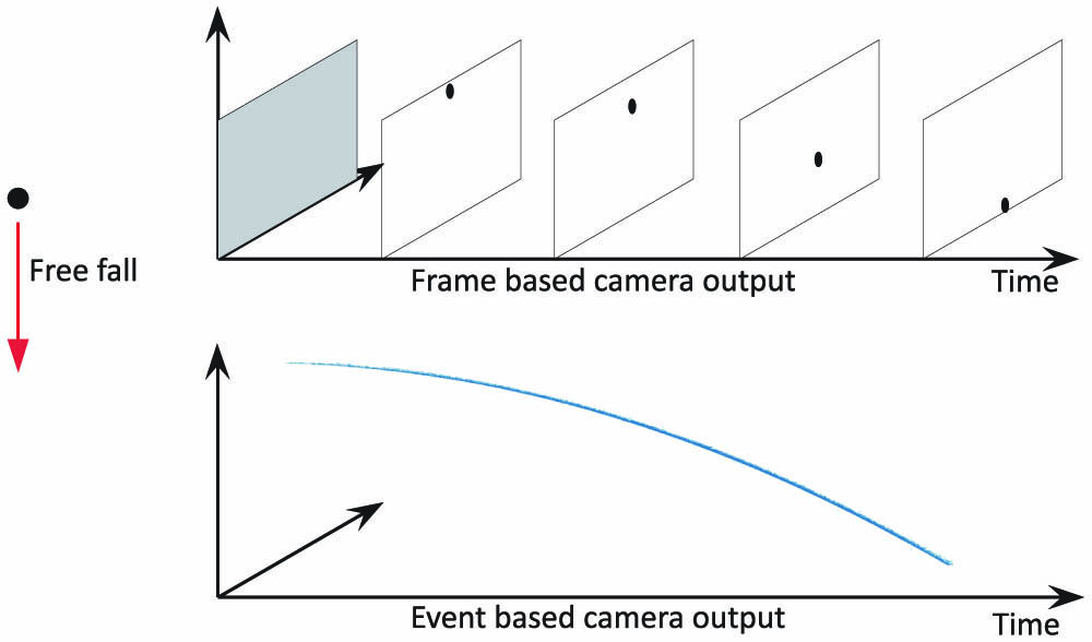
Conventional cameras use frame-based imaging sensors such as complementary metal oxide semiconductors (CMOS) and charge-coupled devices (CCD). A frame-based sensor has the same exposure time for all pixels at the same moment (global shutter) or over a period of time (roll-up shutter) to produce a frame of the entire field of view. However, this frame-based imaging data is very inefficient and redundant in target tracking tasks, where we are only interested in the pixels where the moving target is located. Event camera is an emerging vision sensor that generates ‘events’ by asynchronously detecting the change of illumination intensity at each pixel. The event camera outputs pixel coordinates and time when there is a change in illumination intensity of a pixel that exceeds a set threshold. The output is with low redundancy as data is only generated at the pixel locations where the illumination intensity changes. The advent of event cameras dates back to 1992 when Mahowald[
![]()
Figure 1.Free fall of a small ball photographed by two different types of cameras.
To address problems of camera synchronization difficulties, data redundancy, and motion blur in high-speed target 3D trajectory measurement, in this work, we propose a single-event-camera stereo vision method using a four-mirror adaptor. We have used the proposed method to measure the 3D trajectory and velocity of a particle flight process, and the results show that the method is very suitable. In addition, we have applied the proposed method to the measurement of rotating objects, and the results show that the proposed method can monitor the operational state of high-speed rotating objects at a very low hardware cost. The proposed method provides a new approach for vibration measurement of rotating objects and external monitoring of rotational angles[
Sign up for Chinese Optics Letters TOC. Get the latest issue of Chinese Optics Letters delivered right to you!Sign up now
2. Principle of Single-Event-Camera Stereo Vision
The event camera used in this Letter is the CeleX5-MP ( pixels) from CelePixel Inc., which has various modes such as gray scale, event, and optical flow. The gray-scale mode is the same as a conventional camera, which allows us to calibrate the imaging parameters using conventional calibration methods. A single-view image provides only 2D information about the object’s motion and requires the object’s trajectory to be perpendicular to the camera’s optical axis, which is a great limitation of the application range of event cameras. In order to obtain the 3D trajectory of an object, multi-view measurements are required. Accurate temporal synchronization between multiple event cameras is very difficult, so we used a four-mirror-based monocular stereo vision approach[
![]()
Figure 2.Four-mirror-based monocular stereo vision. (a) Event camera and four-mirror adaptor. (b) Light paths for four-mirror-based monocular stereo vision.
Before the 3D reconstruction[
![]()
Figure 3.Principle of stereo vision 3D reconstruction. (a) Geometric relationships in stereo visual 3D reconstruction. P is a point in the world coordinate system, and Pl and Pr represent the pixel coordinates of the P point projected to the left and right views, respectively. (b) Image of a calibration board taken by the monocular stereo vision system in gray-scale mode.
Solving Eq. (2) provides the world coordinates for points to be measured from pixel coordinates in the left and right views of the monocular stereo vision system.
Since we can obtain the 3D coordinates of the object to be measured at each moment, we can obtain the displacement vector by making the difference between the coordinates of adjacent moments. The derivative of the displacement vector with respect to time can obtain the velocity vector of the object to be measured at this time, and the mode of the velocity vector is the velocity at this time. The proposed measurement system is, in principle, a conventional stereo vision method, but the camera is replaced by an event camera, and the estimation of the measurement accuracy of in-plane and out-of-plane displacements follows the estimation method of the conventional stereo vision.
3. Experimental Results
The event camera used in this Letter costs about 16,000 renminbi (RMB) and has a temporal resolution of . Conventional high-speed cameras with the same time resolution usually cost more than 500,000 RMB. We utilize the 3D measurement capability of the proposed measurement method to measure the 3D trajectory and velocity of a small steel ball hitting the wall and rebounding (Fig. 4). Since there is no guarantee that the object’s motion trajectory is perpendicular to the camera’s optical axis, single-view measurement cannot deal with this situation. We can observe the deceleration of the small ball due to the impact and acceleration after the rebound in Fig. 4(b).
![]()
Figure 4.Trajectory and velocity in 3D of a small steel ball hitting the wall and rebounding. (a) Experimental setup and size of the steel ball (8 mm; the steel ball was painted white because the background plate is black). (b) The 3D trajectory and velocity.
Vibration measurements of rotating components have been of great interest to the engineering field[
We apply the proposed method to the vibration measurement of a rotating disc. The proposed method can measure the 3D trajectory of the marker on the rotating disc, and its vibration information can be obtained by the analysis of the 3D trajectory. The experimental setup is illustrated in Fig. 5. A brushless motor for an unmanned aerial vehicle was used to drive a disc made of acrylic (thickness: 2 mm, diameter: 20 cm). The rotating disc is black with a marker dot painted in white. The marker is about 38 mm from the center of rotation. When the disc rotates, only the movement of the marker points will cause events, so the redundancy of the data will be expected to be very low. Figure 6 shows the event data due to rotation after filtering, from which it can be observed that the speed of the disc is about 75 r/s.
![]()
Figure 5.Experimental setup for vibration measurement of rotating discs. (a) Experimental setup. (b) The marker dot.
![]()
Figure 6.Events obtained in rotating disc vibration measurement experiments. (a) Events acquired by the left virtual camera. (b) Events acquired by the right virtual camera.
Fitting the event data can obtain an expression for the pixel coordinates of the event over time. Combined with the stereo vision calibration results, the 3D coordinates of the marker point can be obtained by 3D reconstruction. From the 3D coordinate information of the marker point, we can get the trajectory and velocity of the marker point during the rotation [Fig. 7(a)]. Extracting the off-plane components of the 3D trajectory of the marker point [Fig. 7(b)] and performing Fourier analysis on them, the spectral distribution can be obtained [Fig. 7(c)]. From the spectrum results, it can be seen that the vibration of the rotating disc mainly consists of the rotational frequency as well as its harmonic frequency response.
![]()
Figure 7.Results of the rotating disc vibration measurement experiments. (a) 3D trajectory and velocity of the marker point during the rotation. (b) Off-plane displacement of the marker point. (c) Spectral analysis of off-plane displacement of the marker points.
4. Conclusion
In summary, we proposed a single-event-camera-based 3D trajectory measurement method for high-speed moving targets. We have used the proposed method to measure the 3D trajectory and velocity of a particle flight process, and the results show that the method is very suitable. In addition, we have applied the proposed method to the measurement of rotating objects, and the results demonstrate that the proposed method can monitor the operational state of high-speed rotating objects at a very low hardware cost. The method proposed in this Letter is intended to be an alternative to expensive high-speed cameras or scanning LDVs in some application scenarios. As demand for event cameras increases in fields such as autopilot and robotics, it is foreseen that the performance of event cameras such as resolution, signal-to-noise ratio, and bandwidth will advance rapidly. It is meaningful to investigate new event-camera-based measurement methods to achieve a breakthrough of the defects of the old methods. The application of the event camera in the field of experimental mechanics will be greatly expanded with the improvement of their performance.
References
[1] Z. Su, J. Pan, S. Zhang, S. Wu, Q. Yu, D. Zhang. Characterizing dynamic deformation of marine propeller blades with stroboscopic stereo digital image correlation. Mech. Syst. Signal Proc., 162, 108072(2022).
[2] J. M. Sebastián, A. Traslosheros, L. Ángel, F. Roberti, R. Carelli. Parallel robot high speed object tracking. International Conference Image Analysis and Recognition, 295(2007).
[3] H. Kim, Y. Yamakawa, T. Senoo, M. Ishikawa. Visual encoder: robust and precise measurement method of rotation angle via high-speed RGB vision. Opt. Express, 24, 13375(2016).
[4] S. Wang, Y. Xu, Y. Zheng, M. Zhu, H. Yao, Z. Xiao. Tracking a golf ball with high-speed stereo vision system. IEEE Trans. Instrum. Meas., 68, 2742(2018).
[5] Z. Liu, J. Yang. A novel video object tracking approach using bidirectional projection. Chin. Opt. Lett., 2, 390(2004).
[6] M. Ye, J. Liang, L. Li, B. Qian, M. Ren, M. Zhang, W. Lu, Y. Zong. Full-field motion and deformation measurement of high speed rotation based on temporal phase-locking and 3D-DIC. Opt. Lasers Eng., 146, 106697(2021).
[7] Z. Sheng, B. Chen, W. Hu, K. Yan, H. Miao, Q. Zhang, Q. Yu, Y. Fu. LDV-induced stroboscopic digital image correlation for high spatial resolution vibration measurement. Opt. Express, 29, 28134(2021).
[8] J. Li, X. Liu, F. Liu, D. Xu, Q. Gu, I. Ishii. A hardware-oriented algorithm for ultra-high-speed object detection. IEEE Sens. J., 19, 3818(2019).
[9] B. Altmann, C. Pape, E. Reithmeier. Temperature measurements on fast-rotating objects using a thermographic camera with an optomechanical image derotator. Proc. SPIE, 10404, 104040P(2017).
[10] B. Altmann, T. Betker, C. Pape, E. Reithmeier. Alignment strategy for an optomechanical image derotator using a laser Doppler vibrometer. Appl. Optics, 58, 6555(2019).
[11] Y. Yin, B. Altmann, C. Pape, E. Reithmeier. Machine-vision-guided rotation axis alignment for an optomechanical derotator. Opt. Lasers Eng., 121, 456(2019).
[12] T. Jin, H. Jia, W. Hou, R. Yamamoto, N. Nagai, Y. Fujii, K. Maru, N. Ohta, K. Shimada. Evaluating 3D position and velocity of subject in parabolic flight experiment by use of the binocular stereo vision measurement. Chin. Opt. Lett., 8, 601(2010).
[13] C. Wang, S. Ma, G. Liu, H. Zhu, Q. Ma. Correction of start-up time difference-induced measurement errors of a high-speed binocular stereovision system. Opt. Lasers Eng., 126, 105861(2020).
[14] L. Yu, B. Pan. Single-camera high-speed stereo-digital image correlation for full-field vibration measurement. Mech. Syst. Signal Proc., 94, 374(2017).
[15] L. Yu, B. Pan. Full-frame, high-speed 3D shape and deformation measurements using stereo-digital image correlation and a single color high-speed camera. Opt. Lasers Eng., 95, 17(2017).
[16] M. Mahowald. VLSI analogs of neuronal visual processing: a synthesis of form and function(1992).
[17] G. Gallego, T. Delbruck, G. Orchard, C. Bartolozzi, B. Taba, A. Censi, S. Leutenegger, A. Davison, J. O. R. Conradt, K. Daniilidis. Event-based vision: a survey. IEEE Trans. Pattern Anal. Mach. Intell., 44, 154(2020).
[18] D. Saner, O. Wang, S. Heinzle, Y. Pritch, A. Smolic, A. Sorkine-Hornung, M. H. Gross. High-speed object tracking using an asynchronous temporal contrast sensor. Vision, Modeling, and Visualization, 1(2014).
[19] Y. Zhou, G. Gallego, H. Rebecq, L. Kneip, H. Li, D. Scaramuzza. Semi-dense 3D reconstruction with a stereo event camera. Proceedings of the European Conference on Computer Vision, 242(2018).
[20] X. Li, W. Li, X. Ma, X. Yin, X. Chen, J. Zhao. Spatial light path analysis and calibration of four-mirror-based monocular stereo vision. Opt. Express, 29, 31249(2021).
[21] Z. Gao, Y. Gao, Y. Su, Y. Liu, Z. Fang, Y. Wang, Q. Zhang. Stereo camera calibration for large field of view digital image correlation using zoom lens. Measurement, 185, 109999(2021).
[22] Z. Gao, F. Li, Y. Liu, T. Cheng, Y. Su, Z. Fang, M. Yang, Y. Li, J. Yu, Q. Zhang. Tunnel contour detection during construction based on digital image correlation. Opt. Lasers Eng., 126, 105879(2020).
[23] Y. Shu, Z. Tan. 3D reconstruction based on spatial vanishing information. Chin. Opt. Lett., 3, 146(2005).
[24] O. Matsushita, M. Tanaka, H. Kanki, M. Kobayashi, P. Keogh. Vibrations of Rotating Machinery(2017).

Set citation alerts for the article
Please enter your email address
© Copyright 2018-2021 | Chinese Laser Press. All Rights Reserved 沪ICP备15018463号-20