• Photonics Research
  • Vol. 9, Issue 8, 1592 (2021)
Zhanyuan Zhang1, Feifei Qin1, Yi Xu1、2、*, Songnian Fu2, Yuncai Wang2, and Yuwen Qin2
Author Affiliations
  • 1Department of Electronic Engineering, College of Information Science and Technology, Jinan University, Guangzhou 510632, China
  • 2Advanced Institute of Photonics Technology, School of Information Engineering, and Guangdong Provincial Key Laboratory of Information Photonics Technology, Guangdong University of Technology, Guangzhou 510006, China
  • show less
    DOI: 10.1364/PRJ.427094 Cite this Article Set citation alerts
    Zhanyuan Zhang, Feifei Qin, Yi Xu, Songnian Fu, Yuncai Wang, Yuwen Qin. Negative refraction mediated by bound states in the continuum[J]. Photonics Research, 2021, 9(8): 1592 Copy Citation Text show less
    (a) Schematic of negative refraction mediated by bound state in the continuum (BIC), where the vertical guiding is based on the BIC. A Gaussian beam is used to excite negative refraction modes as indicated by arrows. (b) A unit cell of the PhC slab is formed by a dielectric pillar (relative permittivity εr=11.56, r=0.4819a)arranged in a triangular lattice with the lattice constant a, and its height h is 0.6627a. (c) Physical mechanism enabling the negative refraction beyond the light cone of the surrounding materials. The red dashed circle indicates the equi-frequency contour (EFC) for the negative refraction modes above the light cone, where the associated BIC and quasi-BIC regions are outlined by the red shadow ring. The blue dashed circle represents the EFC of light cone at the same frequency. The blue dashed arrow indicates the k-vector of the incident plane wave from air, while the red arrow corresponds to the group velocity of the Bloch mode excited in the PhC slab. The solid red line shows the boundary of the first Brillouin zone (FBZ). The vertical blue dashed line indicates the preservation of momentum parallel to the interface during refraction.
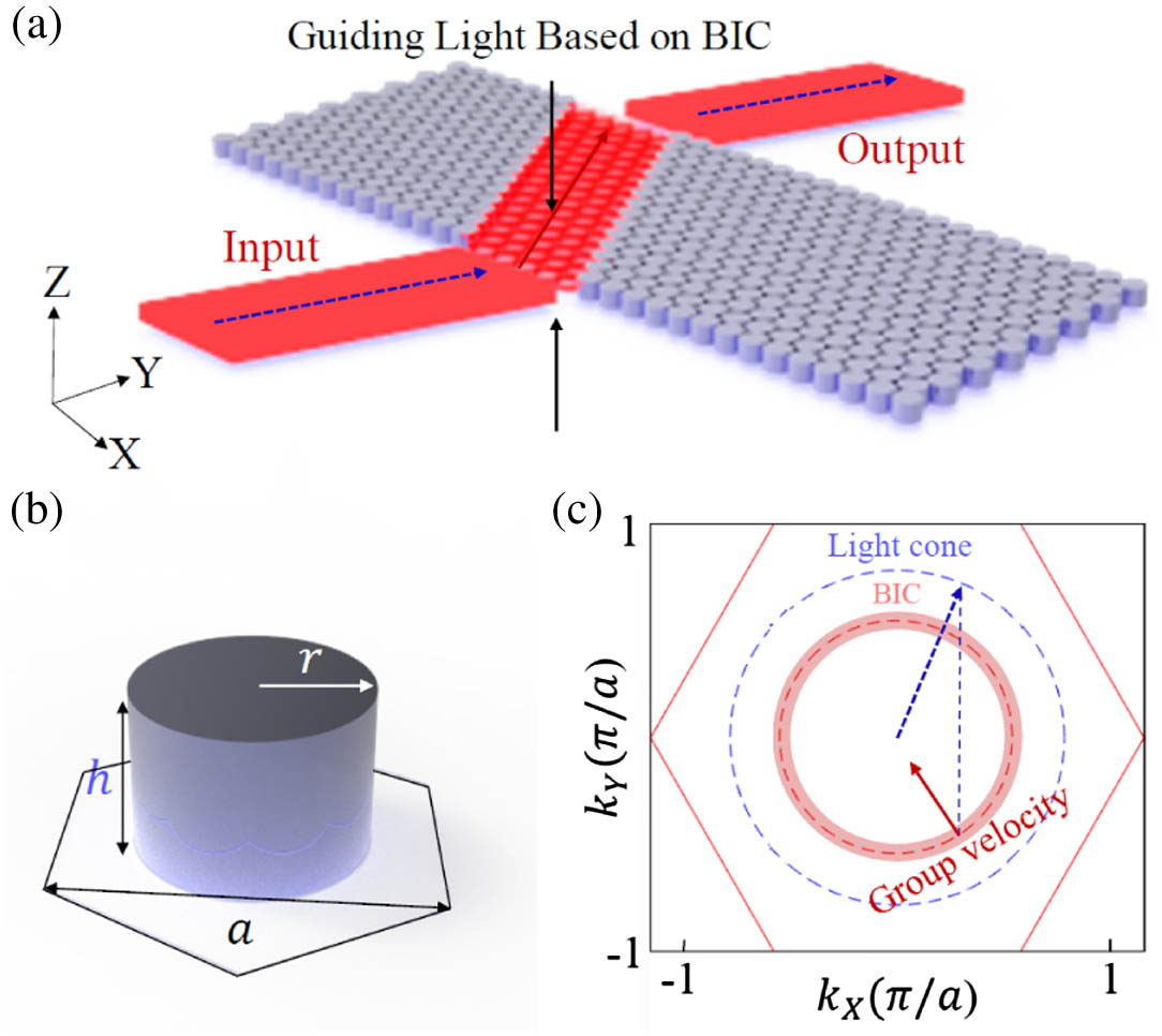
    Fig. 1. (a) Schematic of negative refraction mediated by bound state in the continuum (BIC), where the vertical guiding is based on the BIC. A Gaussian beam is used to excite negative refraction modes as indicated by arrows. (b) A unit cell of the PhC slab is formed by a dielectric pillar (relative permittivity εr=11.56, r=0.4819a)arranged in a triangular lattice with the lattice constant a, and its height h is 0.6627a. (c) Physical mechanism enabling the negative refraction beyond the light cone of the surrounding materials. The red dashed circle indicates the equi-frequency contour (EFC) for the negative refraction modes above the light cone, where the associated BIC and quasi-BIC regions are outlined by the red shadow ring. The blue dashed circle represents the EFC of light cone at the same frequency. The blue dashed arrow indicates the k-vector of the incident plane wave from air, while the red arrow corresponds to the group velocity of the Bloch mode excited in the PhC slab. The solid red line shows the boundary of the first Brillouin zone (FBZ). The vertical blue dashed line indicates the preservation of momentum parallel to the interface during refraction.
    (a) Dispersion properties of PhC slab along the Γ-M direction for three different lattice constants, where the r/a is indicated in the legend. The light cone (black dashed line) is also presented. (b) The corresponding Q factors for the modes shown in (a). (c) The calculated EFCs and the corresponding Q factors of a square region within the first Brillouin zone. The light cone (a/λ=0.3504) is indicated by the blue solid circle. The EFCs for different modes at the same band are marked in the figure, while the color code represents the corresponding Q factors. The blue dashed arrow shows the k-vector of the incident plane wave from air, while the red solid arrow corresponds to the group velocity of the mode excited in the PhC slab. The vertical dashed line indicates the preservation of momentum during refraction.
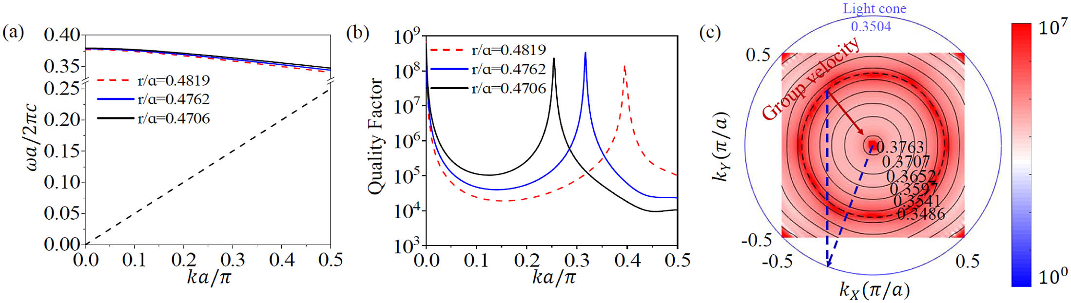
    Fig. 2. (a) Dispersion properties of PhC slab along the Γ-M direction for three different lattice constants, where the r/a is indicated in the legend. The light cone (black dashed line) is also presented. (b) The corresponding Q factors for the modes shown in (a). (c) The calculated EFCs and the corresponding Q factors of a square region within the first Brillouin zone. The light cone (a/λ=0.3504) is indicated by the blue solid circle. The EFCs for different modes at the same band are marked in the figure, while the color code represents the corresponding Q factors. The blue dashed arrow shows the k-vector of the incident plane wave from air, while the red solid arrow corresponds to the group velocity of the mode excited in the PhC slab. The vertical dashed line indicates the preservation of momentum during refraction.
    (a) and (b) Evolution of the magnetic field [Re(Hz)] on the central x–y plane when a Gaussian beam (a/λ=0.3504) is incident into the PhC slab with two different incident angles (θ1=10° and θ2=20°). The directions of the incident, refracted, and outgoing waves are indicated by blue dashed, red solid, and blue dashed arrows, respectively. (c) and (d) EFC analysis of negative refraction for the results shown in (a) and (b), respectively. The blue dashed and red solid arrows indicate the k-vector of the incident wave and the group velocity of the wave refracted by the PhC slab. The red dashed circles represent the EFC of negative refraction modes, whose out-of-plane scattering is prohibited by the quasi-BICs. The blue dashed circles represent their corresponding light cones at the same frequency, respectively.
    Fig. 3. (a) and (b) Evolution of the magnetic field [Re(Hz)] on the central xy plane when a Gaussian beam (a/λ=0.3504) is incident into the PhC slab with two different incident angles (θ1=10° and θ2=20°). The directions of the incident, refracted, and outgoing waves are indicated by blue dashed, red solid, and blue dashed arrows, respectively. (c) and (d) EFC analysis of negative refraction for the results shown in (a) and (b), respectively. The blue dashed and red solid arrows indicate the k-vector of the incident wave and the group velocity of the wave refracted by the PhC slab. The red dashed circles represent the EFC of negative refraction modes, whose out-of-plane scattering is prohibited by the quasi-BICs. The blue dashed circles represent their corresponding light cones at the same frequency, respectively.
    (a) Experimental setup and the fabricated dielectric PhC slab used to demonstrate the negative refraction mediated by quasi-BICs. The red dashed rectangle indicates the measured area in the experiment. (b) The calculated EFCs (black solid lines) and the corresponding Q factors (color coded) of a square region within the FBZ for the PhC slab used in experiment. The blue circle indicates the EFC of light cone (a/λ=0.391). (c) and (d) Experimental results of near-field mapping of Re(S21) of a loop antenna at frequencies of 6.773 GHz and 6.767 GHz for incident angles of 10° and 15°, respectively. The parallel dashed lines indicate the boundaries of the PhC slab.
    Fig. 4. (a) Experimental setup and the fabricated dielectric PhC slab used to demonstrate the negative refraction mediated by quasi-BICs. The red dashed rectangle indicates the measured area in the experiment. (b) The calculated EFCs (black solid lines) and the corresponding Q factors (color coded) of a square region within the FBZ for the PhC slab used in experiment. The blue circle indicates the EFC of light cone (a/λ=0.391). (c) and (d) Experimental results of near-field mapping of Re(S21) of a loop antenna at frequencies of 6.773 GHz and 6.767 GHz for incident angles of 10° and 15°, respectively. The parallel dashed lines indicate the boundaries of the PhC slab.
    Coupling of a Gaussian beam with a stereo incident angle to the on-chip negative refraction mode mediated by the quasi-BICs. The angle between the incident k-vector and the y (z) axis is φ=15° (θ=30°). The structure is similar to that in Fig. 3. Distributions of the calculated magnetic field [Re(Hz)] on the central (b) x–y plane and (c) y–z plane at the red dashed line shown in (b) are presented. The red dashed square indicates the location of the PhC slab.
    Fig. 5. Coupling of a Gaussian beam with a stereo incident angle to the on-chip negative refraction mode mediated by the quasi-BICs. The angle between the incident k-vector and the y(z) axis is φ=15° (θ=30°). The structure is similar to that in Fig. 3. Distributions of the calculated magnetic field [Re(Hz)] on the central (b) xy plane and (c) yz plane at the red dashed line shown in (b) are presented. The red dashed square indicates the location of the PhC slab.
    Zhanyuan Zhang, Feifei Qin, Yi Xu, Songnian Fu, Yuncai Wang, Yuwen Qin. Negative refraction mediated by bound states in the continuum[J]. Photonics Research, 2021, 9(8): 1592
    Download Citation