
Yunqiang Zhang, Jun Chang, Fanyang Dang, Xiaodong Bai, Guoqing Pan. Dynamic aberrations correction of Roll-Nod conformal seeker based on the diffraction surface and anamorphic asphere surface[J]. Chinese Optics Letters, 2020, 18(7): 072201
- Chinese Optics Letters
- Vol. 18, Issue 7, 072201 (2020)
Abstract
The infrared detection method is widely used in precision guided weapons because of its many advantages. The infrared seeker is the core of a guided weapon and generally consists of a dome, an imaging system, and an electronic cabin[
Inspired by the arch corrector, this Letter proposed a method of correcting dynamic aberrations using the diffractive surface and anamorphic asphere surface. The design results show that this method can better correct the dynamic aberrations introduced by the conformal dome, and it is also conducive to simplifying the structure of the conformal seeker.
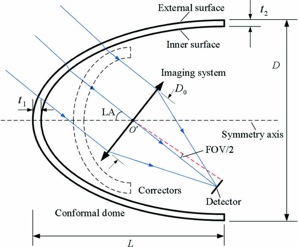
A typical conformal optical system includes a conformal dome, an imaging system, and correctors, as shown in Fig.
Sign up for Chinese Optics Letters TOC. Get the latest issue of Chinese Optics Letters delivered right to you!Sign up now
![]()
Figure 1.Schematic diagram of a conformal optical system.
Parameters describing the conformal optical system are as follows[
Through expanding the wave aberration function in terms of a complete set of Zernike polynomials, we can get the coefficients of Zernike polynomials. Every term of Zernike polynomials has explicit physical meaning, so the coefficients of Zernike polynomials reflect the value of corresponding aberrations[
![]()
Figure 2.Amplitudes of Zernike coefficients of wavefronts passing through a conformal dome.
The seeker can be divided into two types based on the different gimbals used. One type uses an azimuth-elevation-type gimbal, and the other type uses a Roll-Nod-type gimbal[
The fixed corrector is a rotationally symmetric element and has limited correction capabilities of dynamic aberrations. The dynamic corrector will introduce additional motion mechanisms and increases the complexity of the seeker. They are not ideal correction methods. In 1999, Sparrold proposed the arch corrector, which is only capable of Roll-Nod gimbaled missile seekers[
![]()
Figure 3.Arch corrector machined by OPTIMAX company.
The arch corrector is mounted on the Roll frame of the Roll-Nod gimbal and rolls with the imaging system. The imaging system is mounted on the Nod frame, and the optical axis swings within the symmetry plane of the arch corrector, as shown in Fig.
![]()
Figure 4.Conformal seeker with an arch corrector. (a) 0° Roll and 45° Nod; (b) 30° Roll and 45° Nod.
Because of broken rotational symmetry, the arch corrector obtains more design freedom and aberration correction capabilities. Through designing the surface shape, the arch corrector can better correct dynamic aberrations introduced by the conformal dome. Because astigmatism aberrations can be corrected well by non-rotationally symmetric surfaces, the arch corrector is one of the potential solutions to correct the dynamic aberrations in the large FOR[
A major advantage of the arch corrector is that it can produce sufficient astigmatism, which is the main aberration introduced by a conformal dome. Reducing the size of the correction element while retaining sufficient design freedom is the target of this Letter. Inspired by the arch corrector, the design layout of this Letter is shown in Fig.
![]()
Figure 5.Correcting method of dynamic aberrations based on the diffraction surface and anamorphic asphere surface.
Diffractive elements are a type of optical elements based on the principle of optical diffraction, which can change the phase and amplitude of the wave front by etching two or several level relief structures on the substrate. A diffractive lens is mathematically equivalent to a thin lens with an infinite refractive index and has similar aberration characteristics. In order to simplify the structure of the system, the diffractive surface is superimposed on the inner surface of the conformal dome in this Letter.
The phase function of the rotationally symmetric diffraction surface can be described as where is the coefficient of the diffraction phase.
Some researchers have used diffractive elements in correction systems for conformal optics and have verified the feasibility of correcting dynamic aberrations. By analyzing the Zernike aberrations of the wavefront, the phase coefficients and the phase orders of diffractive optical elements used to correct primary Zernike aberrations can be obtained[
The anamorphic asphere surface is bilateral symmetry in both and directions but not necessarily with rotational symmetry. The surface form without the additional aspheric terms is sometimes referred to as a bi-conic surface. The equation is where is the sag of the surface parallel to the axis; , are the curvatures in and directions, respectively; , are the conic coefficients in and directions, respectively; , , , are aspheric coefficients from the 4th to 10th order; , , , are deviations of axisymmetric components from the 4th to 10th order.
For a thin pencil beam, the position of focal lines in the meridian plane and the sagittal plane can be solved by Young’s formulas. The formulas are where is the angle of incidence; is the angle of refraction; and are the object distance and image distance in the meridian plane, respectively; and are the object distance and image distance in the sagittal plane, respectively; and are the curvature radius in the meridian plane and the sagittal plane, respectively.
For different LAs of the conformal dome, the parameters of the diffractive surface and the anamorphic asphere surface can be solved successively by the method of ray tracing. A conformal optical system is designed in this Letter based on the design ideas described above. The parameters are shown in Table
| Term | Parameter Value |
|---|---|
| Material of dome | |
| Diameter | 135 mm |
| Fineness ratio | 1 |
| Thickness at vertex | 3.8 mm |
| Entrance pupil diameter | 35 mm |
| Field of view | |
| Field of regard | |
| Design wavelength |
Table 1. Design Parameters of Conformal Optical System
The initial inner and outer surfaces of the conformal dome are ellipsoids of equal thickness, and they are gradually expanded into asphere surfaces with -order terms during the design process. The diffractive surface is superimposed on the inner surface, and the phase equation of the diffractive surface is[
The optimization result is and . The phase curve of the diffractive surface after optimizing is shown in Fig.
![]()
Figure 6.Phase curve of diffraction surface after optimizing.
For the diffractive element, the diffraction efficiency is a key parameter. The diffraction efficiency can be calculated using the following formula:
For a center wavelength , diffraction order , and the diffraction efficiency at is over 92%.
The optimized conformal optical system at different LAs is shown in Fig.
![]()
Figure 7.Conformal optical system after optimizing. (a) 0° look angle; (b) 70° look angle.
![]()
Figure 8.Designed structure of conformal seeker.
Parameters of the conformal optical system after optimization are shown in Table
| Surface | Type | Radius | Thickness | Glass | Conic |
|---|---|---|---|---|---|
| 1 | Asphere | 43.75 | 3.80 | IRT1 | −0.71 |
| 2 | Asphere | 21.40 | 32.20 | −0.62 | |
| 3 | Asphere | 255.26 | 2.82 | Ge | −21.90 |
| 4 | Asphere | 164.53 | 2.20 | 26.28 | |
| 5 | Asphere | 27.24 | 10.2 | Si | −1.26 |
| 6 | Asphere | 52.91 | 5.18 | −2.37 | |
| 7 | Asphere | 19.23 | 3.08 | Ge | |
| 8 | Asphere | 10.16 | 16.60 | 0.39 | |
| 9 | Anamorphic Asphere | −12.00 | Mirror | ||
| 10 | Sphere | Infinity | Prism | ||
| 11 | Sphere | 33.37 | 2.82 | CaFL | |
| 12 | Sphere | 55.29 | 7.86 | ||
| 13 | Asphere | 27.84 | 3.15 | Si | −0.73 |
| 14 | Sphere | 25.11 | 71.36 | ||
| 15 | Sphere | 1761.31 | 8.00 | ZnSe | |
| 16 | Asphere | −26.49 | 5.20 | −1.40 | |
| 17 | Sphere | −656.83 | 8.45 | Ge | |
| 18 | Sphere | 188.47 | 4.72 | ||
| 19 | Sphere | Infinity | 0.30 | Ge | |
| 20 | Sphere | Infinity | 20.30 | ||
| IMA | Sphere | Infinity |
Table 2. Parameters of Conformal Optical System after Optimization
The spot diagrams of the conformal system at different LAs are shown in Fig.
![]()
Figure 9.Spot diagrams of the conformal system at different look angles. (a) 0°; (b) 30°; (c) 50°; (d) 70°.
![]()
Figure 10.MTF of the conformal system at different look angles. (a) 0°; (b) 30°; (c) 50°; (d) 70°.
In conclusion, a correction method of dynamic aberrations based on the diffraction surface and anamorphic aspheric surface is described. This method is derived from the arch corrector and can only be used on the Roll-Nod gimbal but has a more compact structure. The design results show this method can obtain good imaging performance when designing the conformal optical system. This design method has great advantages in improving system reliability.
References
[1] J. X. Fan, F. Wang. Proc. SPIE, 10433, 1043305(2017).
[2] P. Trotta. Proc. SPIE, 4375, 96(2001).
[3] D. J. Knapp(2002).
[4] B. G. Crowther, D. B. McKenney. Proc. SPIE, 3482, 48(1998).
[5] C. Z. Zhao, Q. F. Cui, S. Mao. Appl. Opt., 55, 2626(2016).
[6] W. Zhang, S. Q. Chen, C. L. Hao, H. H. Wang, B. J. Zuo, Z. G. Fan. Opt. Express, 22, 3514(2014).
[7] D.-L. Song, J. Chang, Q.-F. Wang, W.-B. He, J. Cao. Chin. Phys. B, 20, 074201(2011).
[8] W. Zhang, S. Q. Chen, Z. G. Fan. Opt. Commun., 380, 15(2016).
[9] L. Y. Yu, Q. Wei, J. G. Zheng, M. D. Ge, T. Y. Zhang. J. Opt. Soc. Korea, 20, 64(2016).
[10] L. Y. Yu, Y. F. Hong, Z. F. Cheng, B. Zhang. Chin. Phys. B, 27, 014202(2018).
[11] J. Chang, W. B. He, R. R. Wang, S. L. Feng. Chin. Opt. Lett., 9, 032201(2011).
[12] S. W. Sparrold. Proc. SPIE, 3705, 189(1999).
[13] S. W. Sparrold, D. J. Knapp, P. K. Manhart, K. W. Elsberry. Proc. SPIE, 3779, 434(1999).
[14] J.-G. Liu, Y. Li, L. Li, Y.-F. Huang. Chin. Phys. B, 18, 565(2009).
[15] F. Dang, W. Zhang, S. Q. Chen, H. Wang, J. Yu, Z. G. Fan. Appl. Opt., 55, 8713(2016).
[16] Y. M. Liu, J. Ma, H. P. Ma, X. Z. Jiang. Proc. SPIE, 7544, 75443W(2010).
[17] Z. L. Zhou, H. B. Sang, Y X Sui, H. J. Yang. Chin. Opt. Lett., 16, 032201(2018).
[18] H. H. Jiang, H. G Jia, Q. Wei. Aerosp. Sci. Technol., 23, 345(2012).
[19] S. DeFisher, E. Fess, F. Wolfs. Proc. SPIE, 8708, 870813(2013).
[20] J. D. Nelson, A. Gould, N. Smith, K. Medicus, M. Mandina. Proc. SPIE, 8708, 870815(2013).
[21] W. Zhang, B. J. Zuo, S. Q. Chen, H. S. Xiao, Z. G. Fan. Appl. Opt., 52, 461(2013).
[22] D. Liu, S. B. Wu, W. Yang, L. H. Wang, B. Fan, F. Wu. Chin. Opt. Lett., 16, 090501(2018).

Set citation alerts for the article
Please enter your email address
© Copyright 2018-2021 | Chinese Laser Press. All Rights Reserved 沪ICP备15018463号-20