
Guanghao Shao, Xingwei Ye, Guoqiang Zhang, Yuqi Tan, Jiquan Zhai, Yuhao Yang. In-band intermodulation induced by transient response of erbium-doped fiber amplifier[J]. Chinese Optics Letters, 2022, 20(1): 013901
- Chinese Optics Letters
- Vol. 20, Issue 1, 013901 (2022)
Abstract
Keywords
1. Introduction
Microwave photonics (MWP) continues to be an exciting research field for its usages in optical communication, radio detection and ranging, etc.[
In a typical externally-modulated fiber link, Mach–Zehnder modulator (MZM) and erbium-doped fiber amplifier (EDFA) are fundamental optical devices. Usually, more than one microwave signal is loaded to one optical carrier. For example, in order to maintain an MZM at a suitable bias voltage, a low-frequency dither signal is often introduced. Applied DC voltage is adjusted according to the feedback of the dither signal. In this case, a transmitted RF signal and a dither signal are carried simultaneously. Since the frequency of the dither signal is usually several orders of magnitude lower than that of the transmitted RF signal, in-band intermodulation signals are quite difficult to be filtered. These unwanted signals could be seen as spurious ones, which should be low enough to ensure a large SFDR of the link. However, due to low-frequency perturbation caused by the dither signal, the EDFA’s transient response may add extra modulations upon the RF signal[9,
Though the double tones introduced analog link has already been discussed[
Sign up for Chinese Optics Letters TOC. Get the latest issue of Chinese Optics Letters delivered right to you!Sign up now
2. Theoretical Analysis
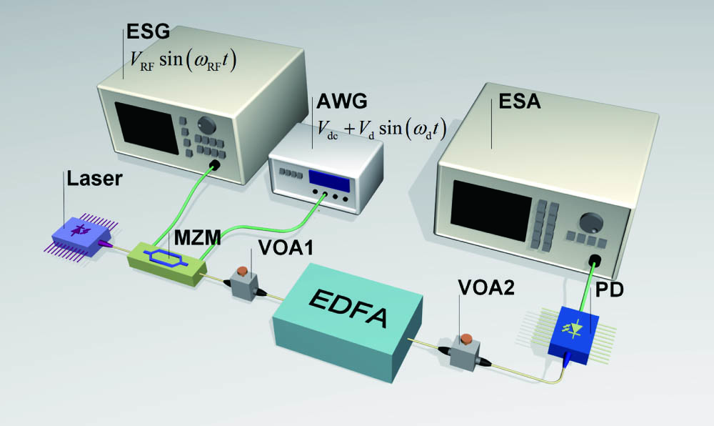
Figure 1 shows a typical schematic for an externally-modulated analog link. Green and yellow lines represent fibers and RF cables, respectively. Light from a laser operating in the 1550 nm band is injected into an MZM. The MZM has two electrical input ports. One port is connected to an electrical signal generator (ESG). The RF signal is expressed as , where and are the amplitude and angular frequency of the signal. The other port is linked to an arbitrary wave generator (AWG), which provides a bias combined by a microwave signal and a DC voltage. In order to distinguish this microwave signal, a “dither signal” is used. The biased signal is described as , where , , and represent the DC voltage, the amplitude, and the angular frequency of the dither signal, respectively. This bias input port could either be a coaxial port or two pins connecting to bias and ground. Variable optical attenuation (VOA) stands for insertion loss of optical devices in the link. A photodetector (PD) is utilized for detecting optical carried microwave signals, which are characterized by an electrical spectrum analyzer (ESA).
![]()
Figure 1.Schematic for analog optical fiber links containing an EDFA.
The instantaneous power of the optical signal after the MZM thus can be expressed as
2.1. Analytical solutions
The EDFA-induced frequency response of an analog photonic link is shown as[
Equation (4) indicates that EDFA could be seen as a high-pass filter in an external-modulated analog link[
To be more specific, due to the relatively long excited state lifetime of erbium, EDFA time-variant gain has a different response to high and low frequencies. It could be affected by low frequencies while hardly being influenced by high frequencies. Therefore, if double tones are introduced containing a low-frequency dither signal and a high-frequency RF signal, the time-variant gain of the EDFA mainly responds to dither signal. Suppose dither signal after EDFA is . The time-variant gain could be obtained as . Therefore, the product of and could give the magnitudes of in-band intermodulation components.
The dither signal after EDFA is in the time domain, while in the frequency domain. and are amplitude variation and phase shift brought by EDFA. Therefore, if considering in Eq. (3), could be obtained.
The above analysis shows that gain and phase response of EDFA are perturbed by the dither signal, which is represented as
Equation (5) shows that EDFA introduces a time perturbed modulation related to , which also affects other signal frequencies such as in-band . RF and its in-band intermodulation signals after the EDFA are
If substituting in Eq. (3) into Eq. (7), in-band frequencies containing , , and could be analytically solved and simplified as
Therefore, CIRs of the first and second-order intermodulation signals, represented as and , thus could be calculated:
Since is much larger than , the third term in the denominator of could be neglected. Different plus and minus symbols are shown between the first two terms in the denominators of Eq. (10), which indicates that first and second-order CIRs may have different variation trends.
2.2. Numerical solutions
Numerical solutions are also given. Consider an EDFA with a steady state input optical power of and the corresponding output power of , which is the same as those in Eq. (4). The input power is perturbed by and is expressed as [], while the output power can be written as [] with perturbation term . Note that is equal to if , i.e., the insertion loss of the first VOA in Fig. 1 is zero. Perturbation terms of and satisfy the following differential equation[9]:
3. Experimental Results
Experimental results of an MZM working at QB are given to compare with the theoretical analysis. The schematic for the link is shown in Fig. 1. Optical power entering the PD is controlled by the second VOA and set as 5 dBm. The RF signal generator produced a 1 GHz signal with 10 dBm. and generated by an AWG are 2.29 V and 0.16 V. The power of the dither signal is about , which is around 2.5% of the RF signal power. Since the dither frequency is quite low, at the dither frequency is close to that of the DC signal. Also, 1 GHz RF signal is applied through a 10 GHz bandwidth MZM to avoid obvious difference. In this case, is the same for the DC, RF, and dither signals. of the MZM is measured to be 4.5 V. Input and output optical powers of the EDFA are set as 5 dBm and 20 dBm, respectively. The relatively large input and output powers could ensure a better compression dynamic range and tolerate large optical insertion loss after the EDFA. Excited state lifetime and intrinsic saturation power are 10.5 ms and 0.15 mW.
The dither signals with 1 kHz, 10 kHz, 100 kHz, and 1 MHz are used as typical frequencies. The electrical spectra are shown in Fig. 2. Apparent spectrum changes are observed. The first-order intermodulation signal varies from to when the dither signal grows from 1 kHz to 1 MHz. It means that 29 dB CIR reductions could be recovered by moving the dither signal from 1 kHz to a higher frequency. For the second order, the variation trend changes. Second-order intermodulation signals grow from to , showing 7 dB variation. Magnitudes of the first and the second-order intermodulation signals indicate that the in-band SFDR is mainly decided by first-order CIR, especially if the dither frequency is low. Different noise floors in Fig. 2 are mainly due to different resolution bandwidth (RBW) values of the ESA.
![]()
Figure 2.In-band electrical spectra at QB with the dither frequency at (a) 1 kHz, (b) 10 kHz, (c) 100 kHz, and (d) 1 MHz. X axis represents offset to 1 GHz center frequency.
The results of CIRs at different dither frequencies are shown in Fig. 3. Since environment conditions, especially temperature, are changing during our experiments, experimental results thus shift around theoretical values. Though a temperature controller could be utilized to reduce fluctuation, the deviation is relatively small and acceptable in our experiments. Therefore, the temperature controller could be saved. For CIR of the first order, it changes slowly at first, which varies from 26 to 29 dBc if the dither signal changes from 1 kHz to 10 kHz. However, it grows rapidly for the dither signal from 20 kHz to 200 kHz. The variation is almost at a rate of 20 dB/decade. For dither frequency above 1 MHz, CIR of the first order stays around 56 dBc, which is similar to links without the EDFA of the same parameters. For CIR of the second order, experimental and numerical results match well, while they have a small difference with the analytical solution at the dither frequency below 30 kHz. It is because modulation terms in Eq. (5) only expand to the first order. Since CIR of the first order dominates SFDR, the aforementioned analytical method is reasonable. The second-order CIR only changes at a dither frequency below 30 kHz and almost remains constant for higher frequency. It goes down from 60 dBc to 53 dBc if the dither signal changes from 1 kHz to 10 kHz, while it grows to 56 dBc at a dither signal of 30 kHz. It remains around 56 dBc for higher dither frequency, which is also equal to cases without an EDFA of the same parameters.
![]()
Figure 3.Experimental, analytical, and numerical results versus dither frequency at QB. (a) CIR of first order; (b) CIR of second order.
The definition of SFDR is a little extended here. The spurious signals caused by the dither signal may be larger than the noise floor, and thus SFDR is equal to the minimum in-band CIR to some extent. In our experiment, the derivation between and QB is about 1% . In-band CIR of the first order is less than that of the second order if the dither signal is lower than 1 MHz. If the dither signal is above 1 MHz, CIRs of the first and second orders are nearly the same, which is shown in Fig. 3. Therefore, SFDR could be seen as a first-order CIR in our experiment. However, if variation is smaller, SFDR may be dominated by second-order CIR. It shows that the CIR of the first order dominates SFDR at a dither frequency below 400 kHz with 0.5% deviation based on Eq. (10) or (11). However, if the dither signal is higher, the CIR of the second order is smaller than that of the first order and plays a major role in SFDR.
4. Discussion
In this work, evolution of double tones in an analog link is analyzed. Additional modulation brought by an EDFA is considered. If both of the frequencies are above the tens of megahertz (MHz) level, the time perturbation effect of an EDFA could be neglected. However, if any of the transmitted frequencies is below 1 MHz, transient response of the EDFA may apparently change in-band intermodulation signals. The CIR of the first order may decrease up to 29 dB. In another word, in-band SFDR thus reduces, which should be better avoided.
Though in-band intermodulation signals are unwanted ones, a dither signal is unavoidable in many cases, especially for engineering applications. A dither signal with small amplitude and low frequency is usually utilized to maintain an MZM working at a proper DC voltage and temperature[
In spite of the MZM based on lithium niobate (LN) discussed above, many other types of external modulators are also used. For example, the III–V semiconductors have been extensively studied as optical modulators, including GaAs and InP[
On the other hand, other types of optical amplifiers, such as semiconductor optical amplifiers, have similar transient responses to EDFA but with a different excited state lifetime and cutoff frequency[
5. Conclusion
In conclusion, transient response of an EDFA is considered in an externally-modulated analog fiber link. In-band CIRs are emphatically analyzed with double tones of several orders of magnitude differences. The low-frequency dither signal perturbs the instantaneous EDFA gain, which superposes another modulation to in-band transmitted RF signals. Such a phenomenon may reduce in-band SFDR, which should be avoided. Analysis in this paper indicates that the dither signal would be better at the MHz level to balance SFDR and feedback processing complexity. The method is easy to realize and could bring significant improvements for applications with low-frequency dither signals in MWP systems.
References
[1] J. Capmany, G. Li, C. Lim, J. Yao. Microwave photonics: current challenges towards widespread application. Opt. Express, 21, 22862(2013).
[2] P. Ghelfi, F. Laghezza, F. Scotti, G. Serafino, A. Capria, S. Pinna, D. Onori, C. Porzi, M. Scaffardi, A. Malacarne, V. Vercesi, E. Lazzeri, F. Berizzi, A. Bogoni. A fully photonics-based coherent radar system. Nature, 507, 341(2014).
[3] V. Urick, F. Bucholtz, J. McKinney, P. Devgan, A. Campillo, J. Dexter, K. Williams. Long-haul analog photonics. J. Lightwave Technol., 29, 1182(2011).
[4] G. Zhang, X. Zheng, S. Li, H. Zhang, B. Zhou. Postcompensation for nonlinearity of Mach–Zehnder modulator in radio-over-fiber system based on second-order optical sideband processing. Opt. Lett., 37, 806(2012).
[5] Y. Bai, M. Zhang, Q. Shi, S. Ding, Y. Qin, Z. Xie, X. Jiang, M. Xiao. Brillouin–Kerr soliton frequency combs in an optical microresonator. Phys. Rev. Lett., 126, 063901(2021).
[6] X. Ye, D. Zhu, Y. Zhang, S. Li, S. Pan. Analysis of photonics-based RF beamforming with large instantaneous bandwidth. J. Lightwave Technol., 35, 5010(2017).
[7] X. Xue, X. Zheng, B. Zhou. Super-efficient temporal solitons in mutually coupled optical cavities. Nat. Photon., 13, 616(2019).
[8] Y. Shi, X. Chen, Y. Zhou, S. Li, L. Lu, R. Liu, Y. Feng. Experimental demonstration of eight-wavelength distributed feedback semiconductor laser array using equivalent phase shift. Opt. Lett., 37, 3315(2012).
[9] Y. Sun, A. Saleh, J. Zyskind, D. Wilson, A. Srivastava, J. Sulhoff. Time dependent perturbation theory and tones in cascaded erbium-doped fiber amplifier systems. J. Lightwave Technol., 15, 1083(1997).
[10] Y. Sun, J. Zyskind, A. Srivastava. Average inversion level, modeling, and physics of erbium-doped fiber amplifiers. IEEE J. Sel. Top. Quantum. Electron., 3, 991(1997).
[11] V. Unick, J. McKinney, K. Williams. Fundamentals of Microwave Photonics(2015).
[12] M. Shtaif, M. Eiselt, R. Tkach, R. Stolen, A. Gnauck. Crosstalk in WDM systems caused by cross-phase modulation in erbium-doped fiber amplifiers. IEEE Photon. Technol. Lett., 10, 1796(1998).
[13] N. Wang, I. Kim, O. Vassilieva, T. Ikeuchi, H. Wen, J. Antonio-Lopez, J. Alvarado-Zacarias, H. Liu, S. Fan, M. Habib, R. Amezcua-Correa, G. Li. Low-crosstalk few-mode EDFAs using retro-reflection for single-mode fiber trunk lines and networks. Opt. Express, 27, 35962(2019).
[14] J. Freeman, J. Conradi. Gain modulation response of erbium-doped fiber amplifiers. IEEE Photon. Technol. Lett., 5, 224(1993).
[15] L. Wang, T. Kowalcyzk. A versatile bias control technique for any-point locking in lithium niobate Mach–Zehnder modulators. J. Lightwave Technol., 28, 1703(2010).
[16] R. Walker, N. Cameron, Y. Zhou, S. Clements. Optimized gallium arsenide modulators for advanced modulation formats. IEEE J. Sel. Top. Quantum. Electron., 19, 3400912(2013).
[17] X. Ruan, L. Zhang, F. Yang, Y. Zhu, Y. Li, F. Zhang. Beyond 100G single sideband PAM-4 transmission with silicon dual-drive MZM. IEEE Photon. Technol. Lett., 31, 509(2019).
[18] M. He, M. Xu, Y. Ren, J. Jian, Z. Ruan, Y. Xu, S. Gao, S. Sun, X. Wen, L. Zhou, L. Liu, C. Guo, H. Chen, S. Yu, L. Liu, X. Cai. High-performance hybrid silicon and lithium niobate Mach–Zehnder modulators for 100 Gbit s−1 and beyond. Nat. Photon., 13, 359(2019).
[19] G. Shao, Y. Bai, G. Cui, C. Li, X. Qiu, D. Geng, D. Wu, Y. Lu. Ferroelectric domain inversion and its stability in lithium niobate thin film on insulator with different thicknesses. AIP Adv., 6, 075011(2016).
[20] Z. Wang, C. Wu, Z. Fang, M. Wang, J. Lin, R. Wu, J. Zhang, J. Yu, M. Wu, W. Chu, T. Lu, G. Chen, Y. Cheng. High-quality-factor optical microresonators fabricated on lithium niobate thin film with an electro-optical tuning range spanning over one free spectral range [Invited]. Chin. Opt. Lett., 19, 060002(2021).
[21] X. Tian, W. Zhou, K. Ren, C. Zhang, X. Liu, G. Xue, J. Duan, X. Cai, X. Hu, Y. Gong, Z. Xie, S. Zhu. Effect of dimension variation for second-harmonic generation in lithium niobate on insulator waveguide [Invited]. Chin. Opt. Lett., 19, 060015(2021).
[22] J. Herrera, F. Ramos, J. Marti. Nonlinear distortion generated by semiconductor optical amplifier boosters in analog optical systems. Opt. Lett., 28, 1102(2003).

Set citation alerts for the article
Please enter your email address
© Copyright 2018-2021 | Chinese Laser Press. All Rights Reserved 沪ICP备15018463号-20