
Yanmei Cao, Ezgi Sahin, Ju Won Choi, Peng Xing, George F. R. Chen, D. K. T. Ng, Benjamin J. Eggleton, Dawn T. H. Tan. Thermo-optically tunable spectral broadening in a nonlinear ultra-silicon-rich nitride Bragg grating[J]. Photonics Research, 2021, 9(4): 596
- Photonics Research
- Vol. 9, Issue 4, 596 (2021)
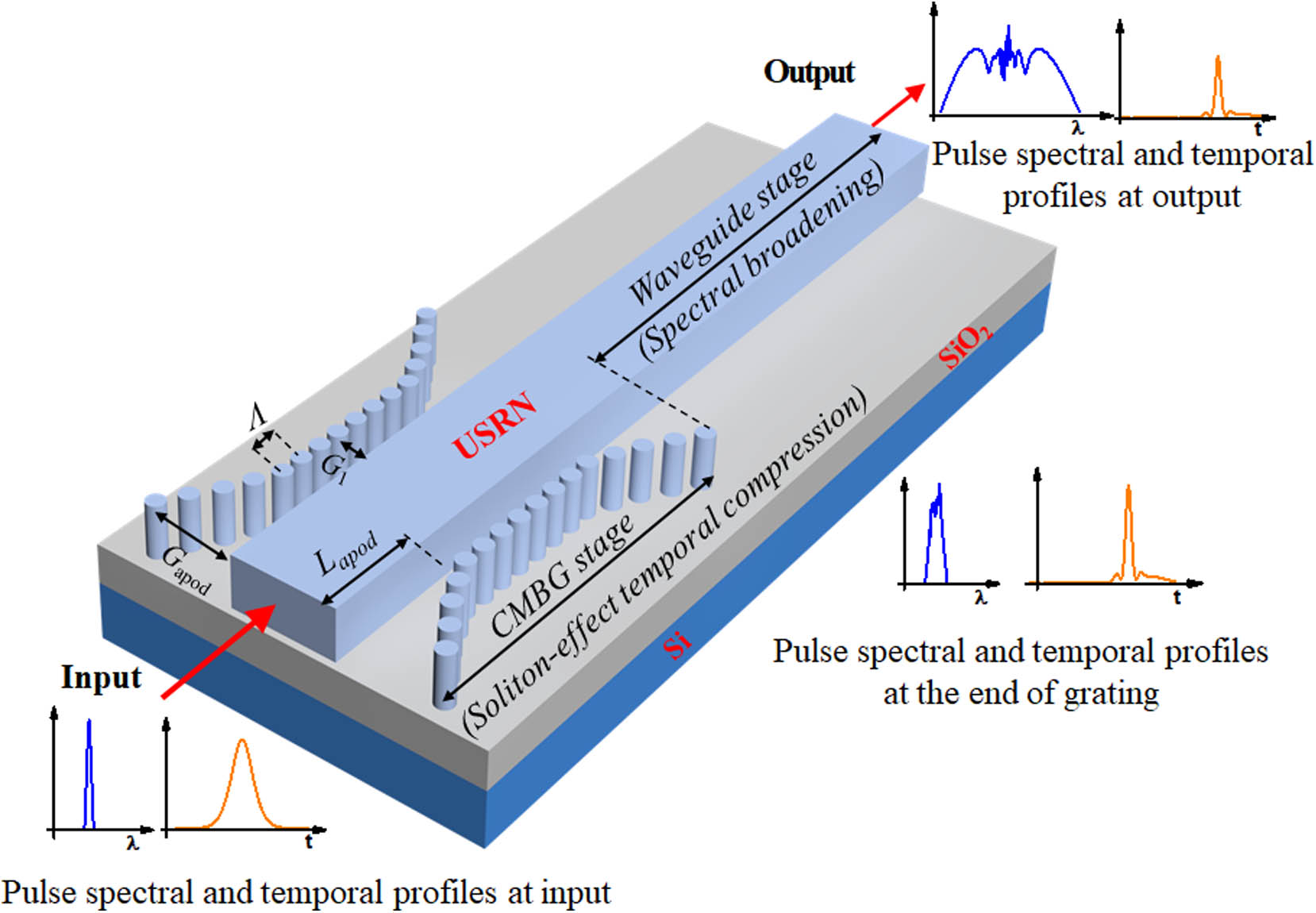
Fig. 1. 3D schematic of the ultra-silicon-rich nitride (USRN) device showing the CMBG and USRN waveguide parameters, where L apod Λ G 1 G apod
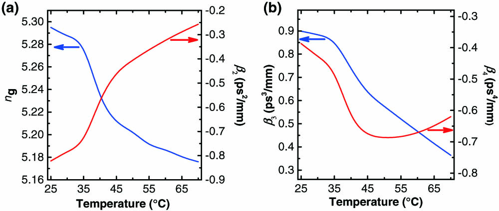
Fig. 2. (a) Group index (n g β 2 β 3 β 4
Fig. 3. (a) Simulated spectral broadening at different temperatures at a fixed pulse wavelength of 1536 nm. Simulated and measured (b) − 30 dB − 20 dB
Fig. 4. (a) Simulated spectral profiles at the end of the CMBG. (b) Simulated temporal profiles as a function of temperature at the end of the CMBG. (c) Simulated temporal FWHM at the end of the CMBG stage for each temperature point.
Fig. 5. (a) Schematic of the experimental setup, where blue lines denote the polarization maintaining (PM) fibers, with DUT, device under test; OSA, optical spectrum analyzer; TLF, tapered lensed fiber; TC, temperature controller; OA, optical attenuator; FFL, femtosecond fiber laser. (b) Measured spectral broadening at different temperatures and the input pulse at a fixed input wavelength of 1536 nm. (c) Measured spectral bandwidth at − 30 dB
Fig. 6. (a) Measured temperature-dependent stopband of a characteristic cladding modulated Bragg grating with a stopband centered at 1557 nm at 25°C. (b) Measured transmission spectra of USRN grating used in the spectral broadening measurement showing the stopband of 1553 nm at 25°C. (c) The measured Bragg wavelength at different temperatures. (d) The measured refractive index of USRN at different temperatures.
|
Table 1. Comparison of Various Approaches toward Tuning of Laser Pulse Bandwidth

Set citation alerts for the article
Please enter your email address
© Copyright 2018-2021 | Chinese Laser Press. All Rights Reserved 沪ICP备15018463号-20