• Advanced Photonics
  • Vol. 5, Issue 2, 026002 (2023)
Wenhe Jia1、†, Chenxin Gao1, Yongmin Zhao2, Liu Li1, Shun Wen1, Shuai Wang1, Chengying Bao1、*, Chunping Jiang2、*, Changxi Yang1, and Yuanmu Yang1、*
Author Affiliations
  • 1Tsinghua University, State Key Laboratory of Precision Measurement Technology and Instruments, Department of Precision Instrument, Beijing, China
  • 2Chinese Academy of Sciences, Suzhou Institute of Nano-Tech and Nano-Bionics, Key Laboratory of Nanodevices and Applications, Suzhou, China
  • show less
    DOI: 10.1117/1.AP.5.2.026002 Cite this Article Set citation alerts
    Wenhe Jia, Chenxin Gao, Yongmin Zhao, Liu Li, Shun Wen, Shuai Wang, Chengying Bao, Chunping Jiang, Changxi Yang, Yuanmu Yang. Intracavity spatiotemporal metasurfaces[J]. Advanced Photonics, 2023, 5(2): 026002 Copy Citation Text show less
    Schematic illustration of the intracavity spatiotemporal modulation using the geometric phase metasurface strongly coupled to an epsilon-near-zero material. The metasurface is incorporated in a unidirectional ring fiber laser cavity. The metasurface converts a portion of the input Gaussian beam into a vortex beam, which is coupled out from the laser cavity through a polarization beam splitter (PBS). The remaining Gaussian beam is further amplified in the following round trip. The giant nonlinear saturable absorption of the strongly coupled system further allows temporal laser pulse compression via the Q-switching process.
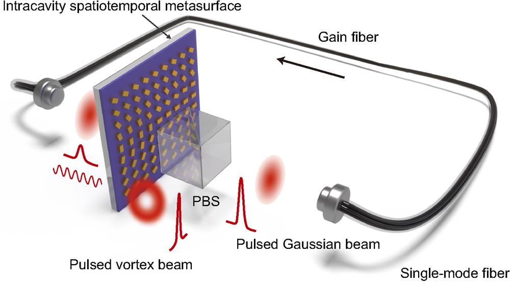
    Fig. 1. Schematic illustration of the intracavity spatiotemporal modulation using the geometric phase metasurface strongly coupled to an epsilon-near-zero material. The metasurface is incorporated in a unidirectional ring fiber laser cavity. The metasurface converts a portion of the input Gaussian beam into a vortex beam, which is coupled out from the laser cavity through a polarization beam splitter (PBS). The remaining Gaussian beam is further amplified in the following round trip. The giant nonlinear saturable absorption of the strongly coupled system further allows temporal laser pulse compression via the Q-switching process.
    Intracavity spatial modulation. (a) Schematic illustration of the optical setup in free space for the vortex beam generation using the geometric phase metasurface directly from the laser cavity. Col, collimator; LP, linear polarizer; QWP, quarter-wave plate; PBS, polarization beam splitter; CCD, charge-coupled device. (b) Schematic of the unit cell of the geometric phase metasurface. (c), (d) Spatial phase distributions required for the generation of vortex beam with topological charge l=1 (c) and l=2 (d), respectively. (e), (f) SEM images at the center of the geometric phase metasurface with topological charge l=1 (e) and l=2 (f), respectively. (g), (h) Transverse mode profiles of the vortex beam with topological charge l=1 (g) and l=2 (h), respectively. (i), (j) Interference patterns between a Gaussian beam and a vortex beam with topological charge l=1 (i) and l=2 (j), respectively.
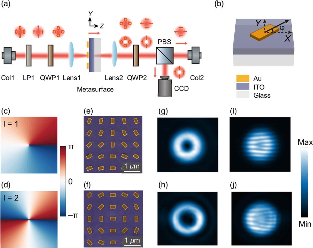
    Fig. 2. Intracavity spatial modulation. (a) Schematic illustration of the optical setup in free space for the vortex beam generation using the geometric phase metasurface directly from the laser cavity. Col, collimator; LP, linear polarizer; QWP, quarter-wave plate; PBS, polarization beam splitter; CCD, charge-coupled device. (b) Schematic of the unit cell of the geometric phase metasurface. (c), (d) Spatial phase distributions required for the generation of vortex beam with topological charge l=1 (c) and l=2 (d), respectively. (e), (f) SEM images at the center of the geometric phase metasurface with topological charge l=1 (e) and l=2 (f), respectively. (g), (h) Transverse mode profiles of the vortex beam with topological charge l=1 (g) and l=2 (h), respectively. (i), (j) Interference patterns between a Gaussian beam and a vortex beam with topological charge l=1 (i) and l=2 (j), respectively.
    Intracavity temporal modulation. (a) Schematic (upper panel) and SEM image (lower panel) of the circular gold nano-antenna coupled to an ITO film. The geometric parameters are: P=760 nm, R=200 nm, t1=40 nm, and t2=20 nm. (b) Real (red) and imaginary (blue) parts of the permittivity of the ITO film. Inset: schematic of the ITO film on glass substrate used in the spectroscopic ellipsometry measurement. (c) Simulated transmittance of the coupled system as a function of the ENZ wavelength of the ITO film. The static ENZ wavelength of the ITO film and the laser operation wavelength are indicated by the white and gray dashed lines, respectively. (d) Measured (red) and simulated (blue) linear transmittance of the coupled system. The gray region denotes the wavelength range where experimental results are not achievable due to the low quantum efficiency of the spectrometer. (e) Simulated electric field intensity distribution at the wavelength of 1565 nm. (f) Measured (dots) and fitted (line) pump fluence-dependent transmittance of the ENZ-metasurface at the wavelength of 1565 nm. The fitting parameters are as follows: Isat=0.52 GW/cm2, A=7.2%, and Ans=34.5%. Inset: schematics of ultrafast electron dynamics in the ITO film with three steps, including photo-excitation, hot-electron redistribution, and relaxation. (g) Schematic of the Q-switching measurement setup. LD, laser diode; WDM, 980 nm/1550 nm wavelength division multiplexer; EDF, Er-doped fiber; ISO, optical isolator; PC, polarization controller; Col, collimator; OC, output coupler. (h) Output Q-switched pulses trace with the pump power of 39 mW. (i) Averaged optical spectrum of the output pulses with a peak wavelength of 1566 nm.
    Fig. 3. Intracavity temporal modulation. (a) Schematic (upper panel) and SEM image (lower panel) of the circular gold nano-antenna coupled to an ITO film. The geometric parameters are: P=760  nm, R=200  nm, t1=40  nm, and t2=20  nm. (b) Real (red) and imaginary (blue) parts of the permittivity of the ITO film. Inset: schematic of the ITO film on glass substrate used in the spectroscopic ellipsometry measurement. (c) Simulated transmittance of the coupled system as a function of the ENZ wavelength of the ITO film. The static ENZ wavelength of the ITO film and the laser operation wavelength are indicated by the white and gray dashed lines, respectively. (d) Measured (red) and simulated (blue) linear transmittance of the coupled system. The gray region denotes the wavelength range where experimental results are not achievable due to the low quantum efficiency of the spectrometer. (e) Simulated electric field intensity distribution at the wavelength of 1565 nm. (f) Measured (dots) and fitted (line) pump fluence-dependent transmittance of the ENZ-metasurface at the wavelength of 1565 nm. The fitting parameters are as follows: Isat=0.52  GW/cm2, A=7.2%, and Ans=34.5%. Inset: schematics of ultrafast electron dynamics in the ITO film with three steps, including photo-excitation, hot-electron redistribution, and relaxation. (g) Schematic of the Q-switching measurement setup. LD, laser diode; WDM, 980 nm/1550 nm wavelength division multiplexer; EDF, Er-doped fiber; ISO, optical isolator; PC, polarization controller; Col, collimator; OC, output coupler. (h) Output Q-switched pulses trace with the pump power of 39 mW. (i) Averaged optical spectrum of the output pulses with a peak wavelength of 1566 nm.
    Intracavity spatiotemporal modulation. (a), (b) Transverse mode profiles of the Q-switched vortex pulses with topological charge l=1 (a) and l=2 (b), respectively. (c), (d) Interference patterns between a pulsed Gaussian beam and a pulsed vortex beam with topological charge l=1 (c) and l=2 (d), respectively. (e) Q-switched pulse trace of the vortex beam (l=2) with a pump power of 51 mW. The FWHM pulse duration is 14.3 μs. (f) Averaged optical spectrum of the pulsed vortex beam (l=2) with a peak wavelength of 1578 nm.
    Fig. 4. Intracavity spatiotemporal modulation. (a), (b) Transverse mode profiles of the Q-switched vortex pulses with topological charge l=1 (a) and l=2 (b), respectively. (c), (d) Interference patterns between a pulsed Gaussian beam and a pulsed vortex beam with topological charge l=1 (c) and l=2 (d), respectively. (e) Q-switched pulse trace of the vortex beam (l=2) with a pump power of 51 mW. The FWHM pulse duration is 14.3  μs. (f) Averaged optical spectrum of the pulsed vortex beam (l=2) with a peak wavelength of 1578 nm.
    Wenhe Jia, Chenxin Gao, Yongmin Zhao, Liu Li, Shun Wen, Shuai Wang, Chengying Bao, Chunping Jiang, Changxi Yang, Yuanmu Yang. Intracavity spatiotemporal metasurfaces[J]. Advanced Photonics, 2023, 5(2): 026002
    Download Citation