Mohammed Sait, Xiaobin Sun, Omar Alkhazragi, Nasir Alfaraj, Meiwei Kong, Tien Khee Ng, Boon S. Ooi. The effect of turbulence on NLOS underwater wireless optical communication channels [Invited][J]. Chinese Optics Letters, 2019, 17(10): 100013
Copy Citation Text
Conventional line-of-sight underwater wireless optical communication (UWOC) links suffer from huge signal fading in the presence of oceanic turbulence due to misalignment, which is caused by variations in the refractive index in the water. Non-line-of-sight (NLOS) communication, a novel underwater communication configuration, which has eased the requirements on the alignment, is supposed to enhance the robustness of the UWOC links in the presence of such turbulence. This Letter experimentally and statistically studies the impact of turbulence that arises from temperature gradient variations and the presence of different air bubble populations on NLOS optical channels. The results suggest that temperature gradient-induced turbulence causes negligible signal fading to the NLOS link. Furthermore, the presence of air bubbles with different populations and sizes can enhance the received signal power by seizing the scattering phenomena from an ultraviolet 377 nm laser diode.
When it comes to practical implementation, the increasing demands for high throughput and high data rates in underwater communication channels have led to a plethora of intensive studies that are focused on finding alternative solutions to deficiencies in acoustic and radio frequency wireless communication technologies. Underwater wireless optical communication (UWOC) is a viable approach to providing better data security, higher data transfer bandwidths, lower time latencies, and robust Doppler spread. UWOC opens a wide range of potential applications, ranging from offshore oil rig and pipeline monitoring to submarine communications. However, UWOC channels are optically quite challenging because they suffer from many difficulties, such as undesired absorption, scattering, and turbulence effects, which can induce fading on the propagation path of a signal. These issues limit the propagation distances to around 100 m[1]. When a signal is prematurely absorbed, the photon energy is converted into other forms of energy, such as heat or kinetic energy, which interact with water molecules or other suspended particles. By contrast, scattering is a process during which photons deviate from their original path because of collisions with water molecules or particles. Because the obstructing particles can be smaller in size compared to the wavelength of the transmission radiation, Rayleigh scattering may occur. To the contrary, scattering from particles that are comparable to the incident propagation wavelengths () can result in Mie scattering. The addition of absorption and scattering coefficients and , respectively, produces the extinction coefficient, which quantifies the total attenuation in the amount of radiation that is passing through a medium[2]:
In recent years, the characterization and modeling of underwater channels in the presence of turbulence effects, such as temperature variations and bubbles, have been extensively studied[3–6]. Moreover, the work in Ref. [5] experimentally investigated the effect of temperature on the UWOC link’s performance, and it was shown that the link experienced high power losses in the presence of turbulence. Furthermore, the work in Ref. [6] showed that shorter wavelengths are the most affected by temperature-induced turbulence in the UWOC channel. In addition to temperature variations, the presence of bubbles was also shown to introduce turbulence-induced fading in Refs. [7,8]. In the latter study, the effect of different air bubbles’ sizes on the bit error ratio performance was experimentally investigated, and it was shown that, with large bubble sizes of , the received intensity fluctuated, which caused total signal loss. Beam expansion was demonstrated to significantly improve the performance degradation in the UWOC channel. Moreover, the study in Ref. [9] experimentally investigated the statistical distribution of intensity fluctuation in the UWOC channel under the presence of bubbles and salinity-induced fading. It was shown that air bubbles mainly introduced severe intensity fluctuations of the propagating signal. Salinity-induced turbulence was investigated by proposing the Weibull model to characterize the statistics of a laser beam’s intensity fluctuations in underwater channels due to the presence of a salinity gradient[10]. A novel turbulence model based on the Monte Carlo simulation method was presented in Ref. [11]. The model was simulated in both weak and moderate turbulence regimes to obtain the probability density function (PDF) of the received intensity; it was found that the experimentally obtained distributions in weak turbulence were fitted with a log-normal PDF. An experimental study of salinity-induced turbulence was also presented in Ref. [6], which showed that salinity-based turbulence has a stronger effect than temperature gradient on communication performance. However, the aforementioned reports were based on line-of-sight (LOS) configurations, which inherently impose strict requirements on positioning, acquisition, and tracking. Strict alignment between the transmitter and the receiver in the underwater environment is challenging due to the varying geometrical terrains, which possess obstacles, such as rocks and hills, as well as planktonic creatures. These obstacles may potentially cause deep fading, scintillation, and/or complete signal loss. Therefore, the non-LOS (NLOS) configuration relaxes the strict alignment requirements and the aforementioned issues. NLOS communication in an underwater environment can be achieved by using the reflection from the water’s surface[12] either with a multiple-sensor network[13] or by the scattering of water molecules[14]. The characterization of the impulse responses of the NLOS UWOC channels using the Monte Carlo simulation and the Henyey–Greenstein model are presented in Ref. [15]. Because the NLOS configuration is considered, the detector receives light only due to the scattering process; therefore, the attenuation may not be described as simply the summation of the absorption and scattering coefficients, as shown in Eq. (1). However, the diffusion theory could be applied in such a case. When a laser beam enters a medium, the radiance can be expressed as the coherent intensity and the diffuse intensity such that , where is the coherent intensity, which is the incident intensity reduced by the attenuation due to scattering and absorption. In this experiment, the coherent intensity was neglected by using a beam dump, while the diffused intensity was considered for the NLOS experiment. If the medium is mostly scattering, the diffuse intensity tends to be almost isotropic, and the diffuse radiance has a broad angular spread. Therefore, we can expand the diffuse intensity in a series of spherical harmonics. The first two terms of the expansion constitute the diffusion theory[16], where is a unit vector in the direction of propagation, is the deviated intensity in all directions, and is the diffused radiant flux density measured in . The diffuse radiant energy fluence rate satisfies the diffusion equation where is defined as where is the incident radiant flux density (i.e., irradiance), and is the optical depth. The transport coefficient is typically utilized to characterize the diffuse radiant process, which is expressed as where is the mean cosine of the scattering pattern. Notably, the transport coefficient is much smaller than the attenuation coefficient. In order to account for all sources of attenuation within the optical path, path loss was adopted as a figure-of-merit to characterize the NLOS communication channel because a lower path loss indicates a higher communication data rate. It is affected not only by the channel geometries but also by the water turbidity, transmission power, range, and wavelength that are utilized in the data transmission channel[17], as calculated by where is the path loss, and and are the transmitted and received power, respectively. We executed the first experiment on NLOS UWOC in 2018[17], where we investigated the effect of the angular geometry as well as the separation distance between the transmitter and the receiver. To measure the fading strength, it is common in the literature to define the scintillation index of the propagating light wave as[1]where is the instantaneous intensity, and denotes the expected value of the random variable. In this work, to the best of our knowledge, we are the first to investigate the effect of turbulence that is induced by a temperature gradient and different bubble populations on NLOS UWOC channels. We have characterized the results that were obtained by determining the statistical distribution and examining their accuracy in terms of goodness of fit (GoF).
GoF is one way to evaluate the difference between the acquired data that is obtained from an experiment and the theoretical statistical distribution that is obtained from the associated PDF. The GoF, which is also referred to as the measure, is defined as[9]where is the sum of the square errors of the statistical distribution under consideration, and it is defined as , where is the number of bins of the data histogram; and are the predicted and measured values for a given realization that corresponds to the th bin; and is the sum of the square distances, respectively, between the measured points and their mean [i.e., , where .
Sign up for Chinese Optics Letters TOC. Get the latest issue of Chinese Optics Letters delivered right to you!Sign up now
The Gaussian distribution is one of the most commonly used normal distributions in several research fields because of its simplicity and symmetry. It is defined by two parameters—the mean and the variance —by the following PDF:
The log-normal distribution is widely used in scholarly literature to describe the intensity fluctuation in the weak to the moderate regimes (i.e., ). The channel fading coefficient with a PDF is expressed as where is the variance of the log amplitude , and . The variance is related to the scintillation index through [18].
The exponential distribution is a special case of the gamma distribution. The PDF of a random variable can be described by exponential distribution when a single parameter is given by
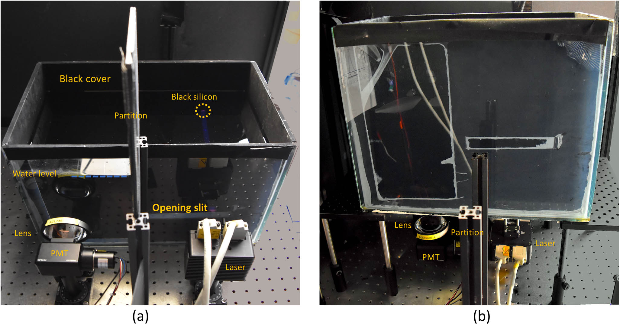
The experimental setup that was employed in this study is illustrated in Fig. 1. At the transmitter side, an ultraviolet (UV) laser (Thorlabs L375P70MLD) was used as a transmitter, with a maximum output power of 70 mW and a peak wavelength of 377 nm. For cooling, TE-cooled mounts (Thorlabs TCLDM9) and a thermoelectric controller (TEC, Thorlabs ITC4001) were mounted on and connected to the laser-diode module. Figure 1 shows that the experimental setup was employed in two configurations. The first configuration [Fig. 1(a)] was used to investigate the impact of bubbles on the NLOS communication link. The laser beam was launched from the side of the water tank with the dimensions of while it was filled with Harbor II water [i.e., , , and ]. The laser beam was propagated through the transparent glass, which has a transmittance of ∼94% at the wavelength under investigation. The interior of the water tank was fully covered by a black cover to eliminate any internal reflections that might be caused by scattered photons from the sidewalls of the water tank. Moreover, a beam dump, which was made of structured black silicon nano-antennas and fabricated using the recipe in Ref. [19], was utilized to absorb and diminish the reflections of the laser beam. The measured reflectivity spectra, using UV-3600 (UV-VIS-NIR spectrophotometer, Shimadzu) (Fig. 2) suggest that the beam dump exhibits a reflectivity of 0.643%, while the black sheet has a reflectivity of 1.24% at an incident-light wavelength of 377 nm. Consequently, by using this setup, it can be conjectured that the received signal was caused by photons scattering from the laser beam. At the receiving end, a photo-multiplying tube (PMT) was used (R928, Hamamatsu) with a quantum efficiency of 25% and a cathode radiant sensitivity of 70 mA/W at an incident-light wavelength of 377 nm. In addition, the PMT was attached to a high-voltage power supply socket assembly (C12597-01, Hamamatsu) with a 0–1250 V operable voltage range. Notably, the PMT is a negative-biased assembly (C12597-01, Hamamatsu) with a 0–1250 V operable voltage range. Notably, the PMT is a negative-biased device; hence, the output data must be inverted. Finally, the PMT module was attached to a plano-convex lens (ACL7560U-A, Thorlabs) to collect the scattered photons within the PMT’s field of view (FOV). The second setup [Fig. 1(b)] was employed to study the effect of the temperature gradient on the optical communication link. As shown in Fig. 1(b), the laser and the photodetector were placed at the bottom of the tank, while the laser beam was propagated towards the water’s surface. The black cover was placed and submerged just below the water surface. The black silicon beam dump was attached to the cover and placed at the opposite side of the laser. To create a temperature gradient, two identical refrigerated/heating circulators (Julabo F12) were used to control the water channel’s temperature conditions by injecting hot water at the top of the water tank and cold water at the bottom because hot water exhibits lower density, while cold water exhibits higher density. Consequently, hot water is preserved at the top, while cold water is kept at the bottom. This would create a temperature gradient within the tank, which would mimic realistic scenarios in oceans. We varied the temperature gradient from ∼0 to 0.4°C/cm, while the mean temperature was kept at 25°C (Table 1). Bubble generation was ensured by using a 0.25 in. copper pipe with a 1 mm hole diameter that was directly connected to the laboratory dry air system. In addition, a submersible fountain pump (Halobao B103) was placed in front of the air pipe to break up and produce bubbles in four different sizes: small, medium, large, and x-large (Fig. 3). To characterize the bubbles’ effects on the communication channel, we calculated the four different bubble sizes by capturing bubble images with a digital camera (Nikon D5500) to observe the distribution. The images were then processed using “ImageJ” software to calculate the size spectra and frequency of their occurrence. Figures 3(a)–3(d) show the obtained photographs and corresponding histograms of the four air bubble populations. As the pump rate increased, the air bubble population became smaller in size and larger in number, as shown in the inset images. The calculated mean bubble areas were 5.2, 13.5, 52, and for the small, medium, large, and x-large sizes, respectively. For example, at the maximum pump rate, there were 85+ bubbles with a mean area of ; conversely, when the pump was off, there were ∼8 bubbles with a mean area of . Figure 4 shows the received signal through the Harbor II water, which was captured using an oscilloscope with a sampling rate of 500 kS/s. It can be concluded from Fig. 4(a) that the received signal, when no artificial turbulence was induced, was approximately constant over time. The scintillation index for this scenario was calculated to be , which corresponds to a weak turbulence regime (i.e., below 0.01). It is believed that such scintillation was introduced because of different types of underlying noise in the equipment used, such as thermal noise, which inherently induces a Gaussian-like distribution. Moreover, the acquired histogram distribution of the corresponding signal is illustrated in Fig. 5(a). The distribution in the figure agrees with the Gaussian and log-normal PDFs, with acceptable GoF values of 0.98031 and 0.97994, respectively, while the exponential distribution intuitively failed. However, other well-known distributions in the literature, such as either the generalized gamma, Weibull, gamma-gamma, or the more advanced double-lobe statistical distributions, such as exponential log-normal[4] and exponential gamma distributions[20], could better fit the acquired data. Figures 5(b) and 5(c) depict the histograms for small and medium bubbles, which correspond to the scintillation indices of and 0.1569, respectively. At such scintillation index values, the laser beam is considered to propagate through the weak to the moderate turbulence regimes (i.e., ), which can be well-fitted using the log-normal distribution with acceptable GoFs of 0.99972 and 0.93740, respectively. We can observe that, while bubbly UWOC links under relatively strong fading, such as and , as shown in Figs. 4(d) and 4(e), respectively, the corresponding histogram distribution in Figs. 5(d) and 5(e) can be fitted using the exponential distribution with a GoF of 0.97964 and 0.99688, respectively. In addition, Figs. 4(b)–4(e) show that, as the bubble sizes increase, the received signal tends to have rapid spikes, which increase the received power, and the gaps between peaks increase. This is attributed to the decrease in the bubble population, and the laser beam in this case can propagate without being obstructed with air bubbles. Therefore, there is a compromise between the frequency of the peaks’ occurrences and the amplitude. Figure 5(f) shows the relationship between the mean bubble size and the scintillation index and the normalized received power (NRP). Importantly, the NRP was calculated based on the received power when there were no bubbles; hence, the NRP for the no-bubble scenario is 0 dB. The increase in bubble size results in an increase of the bubble’s surface area, which in turn leads to more interaction with the photons from the laser beam. Therefore, the probability that a photon will cause a reflection from the bubble at random angles (i.e., depending on the facet geometry of the bubble at the interaction time) increases. The random reflection/refraction from the air bubble in random directions (i.e., scattering) causes a fluctuation in the received intensity, which is proportional to the fluctuation variance (i.e., scintillation index), as shown in Eq. (7). When considering the scattering of light due to air bubbles in water, the refractive index of the bubble is less than that of the surrounding media, which results in a contribution of the total reflection to scattered irradiance at certain angles. For an arbitrary ray incident on a bubble, the angle of incidence is where is the refractive index of air, and is the refractive index of water. The corresponding critical scattering angle is[21]at a wavelength of 377 nm, and the refractive index of the water is . Therefore, the critical incident angle and the critical scattering angle are and , respectively. The presence of a total reflection greatly enhances the light that is scattered into the region and is subtended by . In this case, the region covers all the forward directions. However, a complete understanding of scattering will require consideration of the effects of interference of the reflected light with other transmitted light. The rigorous solution of the scattering pattern can be numerically evaluated by the partial wave Mie theory. In addition, the reflection of an air bubble causes the deviated photons to enter the FOV of the photo-detector, which increases the received power. Unlike the LOS configuration, where large bubbles may cause either a deep fade in signal strength or complete signal loss[8], strong turbulence-induced fading that is caused by bubbles enhances the received power in the NLOS configuration. When considering a realistic scenario, where other factors come into play with the long optical communication link, such as planktonic particles and other scattering agents in oceanic water, the NLOS becomes even more robust with the aid of automatic gain control. However, salinity is one aspect that is believed to attenuate the overall NLOS UWOC’s performance. This is because salinity mainly contributes to absorption (instead of light scattering by particles), which results in attenuated optical power as a consequence. Let us consider the scattering that is caused by the turbulent medium for mathematically explaining these results. The radar equation for the case of a turbulence-induced scattering process is given by[22]where is the bistatic scattering cross-section per unit volume of the turbulence, and it is given by the spectral density of the turbulence[22]:
Inlet 1 Temperature (°C)
Inlet 2 Temperature (°C)
Temperature Gradient (°C·cm−1)
Mean Temperature (°C)
20
30
∼0.4
25
22
28
∼0.2
25
25
0.0
Table 1. Different Temperature Values Used to Create the Temperature Gradient
Figure 3. Photographs of four different air bubbles in the water channel under four different water circulation levels with corresponding bubble size histograms.
Figure 4.Optical signal through bubbly water with (a) no bubbles with ; (b) small bubbles with ; (c) medium bubbles with ; (d) large bubbles with ; and (e) x-large bubbles with .
Figure 5.Histograms of the received optical signal through bubbly water with (a) no bubbles with ; (b) small bubbles with ; (c) medium bubbles with ; (d) large bubbles with ; and (e) x-large bubbles with . (f) A plot of the scintillation index and normalized received power against the mean bubble area.
The cross-section is proportional to the spectral density at the turbulent eddy size , representing the Bragg scattering, is the wavenumber, and and are the transmitter and receiver gain, respectively. The air bubbles cause a multi-path effect and, hence, inter-symbol interference. However, the study intended to prove that the increase of turbulence in NLOS UWOC channels improves the received power. Regarding system performance in a utilized optical communication link, other techniques should be employed to make this technology feasible for deployment. One way to obtain a usable communication link with this technology is the careful selection of modulation schemes. Spectral efficient orthogonal frequency division multiplexing, which is an efficient technique, is one of the available multi-carrier modulations. It can effectively resist multi-path interference so that the signal can be reliably received.
Next, we will consider the received signal variation that is caused by the presence of a temperature gradient. We artificially created a temperature gradient from two chillers and considered the temperature gradient per centimeter (cm) rather than the mere difference of temperature between hot and cold water. In our experiment, we changed the bubble-generation experimental setup (i.e., from a horizontal configuration to a vertical configuration) so that we could achieve a stable temperature gradient. This was achieved because we injected hot water at the surface and cold water at the bottom of the tank. Water molecules with different temperatures will not equilibrate rapidly due to the difference in densities, which results in a more stable measurement. Figure 6(a) shows the received optical signal in the presence of different temperature gradients. In addition, it shows that the received intensity is constant throughout all the temperature gradients. Therefore, it can be conjectured that, in the NLOS UWOC channels, the presence of a temperature gradient has a negligible effect, unlike with the LOS configuration, in which the temperature increases the scintillation index. The NRP scintillation index against the temperature differences is plotted in Fig. 6(b), which shows that no effects were induced on either the received power or the scintillation index when the temperature gradient was increased.
Figure 6.(a) Received optical signal through the temperature difference corresponding to 0°C, 6°C, and 10°C; (b) a plot of the scintillation index and normalized received power against the mean bubble area.
In conclusion, this study provided a comprehensive investigation on the effect of temperature and bubble-induced turbulence in an NLOS UWOC link. The results show that, in the presence of bubbles, and different from conventional LOS UWOC links, the received signal in an NLOS UWOC link does not experience signal fading. Contrarily, the bubbles improve the received power, which further increases with increased bubble size. A brief statistical study of the received optical power under different bubble sizes was also carried out. To evaluate the statistical results, we used the GoF as an evaluation metric. The results show that, when moving from weak to moderate bubble-induced turbulence regimes, the log-normal distribution is well-suited for describing the fading statistics, whereas the exponential distribution stands out for modeling the strong turbulence regime. Moreover, regarding temperature gradient-induced turbulence, it was found that it causes negligible signal fading to the NLOS. In addition, the NLOS UWOC links are resilient to the temperature gradient-induced turbulence, while the effects of bubbles in fact benefit the NLOS UWOC’s performance, unlike LOS channels. Other parameters can also be considered for future study, such as pressure and the effect of different salinity concentrations, to obtain a comprehensive study of this technology. Accurate and thorough statistical as well as experimental investigations in the real oceanic environment are of paramount importance because studies in the literature are mainly focused on turbulence effects in a laboratory environment.
[2] L. C. Andrews, R. L. Phillips, C. Y. Young. Laser Beam Scintillation with Applications(2001).
[3] M. P. Bernotas, C. Nelson. Proc. SPIE, 9827, 98270D(2016).
[4] M. V. Jamali, A. Mirani, A. Parsay, B. Abolhassani, P. Nabavi, A. Chizari, P. Khorramshahi, S. Abdollahramezani, J. A. Salehi. IEEE Trans. Commun., 66, 4706(2018).
[6] H. M. Oubei, X. Sun, T. K. Ng, O. Alkhazragi, M.-S. Alouini, S. B. Ooi. 2018 Fourth Underwater Communications and Networking Conference (UComms), 1(2018).
[7] J. A. Simpson, B. L. Hughes, J. F. Muth. OCEANS 2009, 1(2009).
[8] H. M. Oubei, R. T. ElAfandy, K. H. Park, T. K. Ng, M. S. Alouini, B. S. Ooi. IEEE Photon. Soc. IPC 2017, 9, 441(2017).
[9] M. V. Jamali, P. Khorramshahi, A. Tashakori, A. Chizari, S. Shahsavari, S. AbdollahRamezani, M. Fazelian, S. Bahrani, J. A. Salehi. 2016 Iran Workshop on Communication and Information Theory (IWCIT), 1(2016).
[10] H. M. Oubei, E. Zedini, R. T. ElAfandy, A. Kammoun, T. K. Ng, M.-S. Alouini, B. S. Ooi. 2017 Opto-Electronics and Communications Conference (OECC) and Photonics Global Conference (PGC), 1(2017).
[14] W. Liu, D. Zou, Z. Xu, J. Yu. 2015 IEEE International Conference on Cyber Technology in Automation, Control, and Intelligent Systems (CYBER), 1265(2015).
[15] V. K. Jagadeesh, A. Choudhary, F. M. Bui, P. Muthuchidambaranathan. Proceedings of 4th International Conference on Advances in Computing and Communications, 77(2014).
[18] M. V. Jamali, A. Mirani, A. Parsay, B. Abolhassani, P. Nabavi, A. Chizari, P. Khorramshahi, S. Abdollahramezani, J. A. Salehi. IEEE Trans. Commun., 66, 4706(2018).
Mohammed Sait, Xiaobin Sun, Omar Alkhazragi, Nasir Alfaraj, Meiwei Kong, Tien Khee Ng, Boon S. Ooi. The effect of turbulence on NLOS underwater wireless optical communication channels [Invited][J]. Chinese Optics Letters, 2019, 17(10): 100013