• Chinese Optics Letters
  • Vol. 19, Issue 3, 031901 (2021)
Yan Guan1, Fang Wang2, Ying Yang2, Deen Wang2, Xin Zhang2, Qiang Yuan2, Dongxia Hu2、3, Xuewei Deng2、3、*, Huaijin Ren4, Yuanlin Zheng1, and Xianfeng Chen1、5、**
Author Affiliations
  • 1State Key Laboratory of Advanced Optical Communication Systems and Networks, School of Physics and Astronomy, Shanghai Jiao Tong University, Shanghai 200240, China
  • 2Laser Fusion Research Center, China Academy of Engineering Physics, Mianyang 621900, China
  • 3IFSA Collaborative Innovation Center, Shanghai Jiao Tong University, Shanghai 200240, China
  • 4Institute of Applied Electronics, China Academy of Engineering Physics, Mianyang 621900, China
  • 5Collaborative Innovation Center of Light Manipulation and Applications, Shangdong Normal University, Jinan 250358, China
  • show less
    DOI: 10.3788/COL202119.031901 Cite this Article Set citation alerts
    Yan Guan, Fang Wang, Ying Yang, Deen Wang, Xin Zhang, Qiang Yuan, Dongxia Hu, Xuewei Deng, Huaijin Ren, Yuanlin Zheng, Xianfeng Chen. Variation in linear susceptibility tensor at crystal surface probed by linear Cherenkov radiation[J]. Chinese Optics Letters, 2021, 19(3): 031901 Copy Citation Text show less

    Abstract

    At the surfaces of crystals, linear susceptibility tensors would differ from their counterparts in the interior of the bulk crystal. However, this phenomenon has not been shown in a visible way yet. In previous researches, numerous types of nonlinear Cherenkov radiation based on different materials have been studied, while linear Cherenkov radiation is barely reported. We experimentally prove the generation of linear Cherenkov radiation on the potassium dihydrogen phosphate (KDP) crystal surface and theoretically analyze its phase-matching scheme. In our study, o-polarized light and e-polarized light can mutually convert through the linear Cherenkov process. According to this result, we figure out new nonzero elements at off-diagonal positions in the linear susceptibility tensor matrix at crystal surfaces, compared with the normal form of a bulk KDP.

    1. Introduction

    In nonlinear optics, when discussing the origin and expression of harmonic generation, it always begins with the equation P=ε0[χ(1)E+χ(2)E2+χ(3)E3+],where χ(1) is linear optical susceptibility, and χ(2) and χ(3) are the second- and third-order nonlinear optical susceptibilities, respectively. Equation (1) implies that polarization can be seen as a bridge to investigate each order of harmonic generation of various nonlinear phenomena.

    On the other hand, the equation of polarization may also contain linear components in some specific circumstances, and thus Plinear could correspondingly result in a first-order harmonic generation in theory. However, if we want to observe and study this harmonic generation, it is necessary to separate the input and newly created first-order components exactly in the output beam, which is exiting the nonlinear material. Actually, extending some concepts in nonlinear optics based on ordinary cognition could help to verify our assumption.

    Nonlinear Cherenkov radiation (CR) is a series of special nonlinear phenomena that has attracted some attention in recent years.

    This concept originates from an early theory in particle physics called CR reported in1934 for the first time, to the best of our knowledge[1]. In Ref. [1], Cherenkov reported a special radiation form. The ouput wavefront constituted a cone around the path of charged particles. For CR, the excitation source and stimulated beam propragate along different directions.

    From 1970 on, the theory of CR was introduced into nonlinear phenomena for the first time, to the best of our knowledge; Tien et al. observing Cherenkov second harmonic generation (CSHG) was the beginning[2]. In nonlinear optics, the excitation source becomes input fundamental waves (FWs) instead of charged particles. One distinguishing feature of Cherenkov-type harmonic generation is that the polarization wave stimulated by input light should propagate faster than the output harmonic generation, which means that the wave vectors of input FWs and output harmonic usually differ with each other in both direction and length. Taking CSHG as an example, Fig. 1 shows that there will be a specific angle (called the CR, i.e., θc) between the fundamental beam and second harmonic. This feature has also been shown in material with an artificial structure[3] and vortex beam[4]. Analogously, subsequent phenomena, such as Cherenkov third harmonic generation (CTHG)[5,6], Cherenkov high-order harmonic generation[7], and Cherenkov sum frequency generation (CSFG)[810], share these typical automatic vertical phase-matching characteristics. Therefore, we can infer that linear harmonic generation should have similar emission modality. This means that we could probably recognize both FW and harmonic generation in a simple way.

    Phase-matching scheme of CSHG.

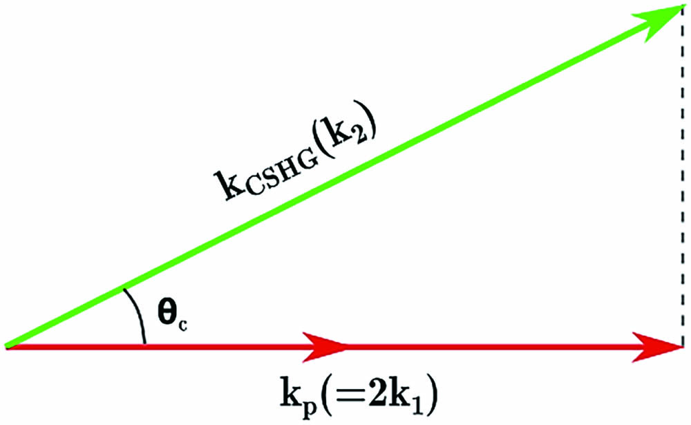
    Figure 1.Phase-matching scheme of CSHG.

    Researches on nonlinear CR (NCR) are often based on waveguides[11,12], nonlinear photonic crystals[13,14], nonlinear boundaries[1517], etc. A nonlinear boundary is quite convenient to employ for its relatively simple structure and high efficiency. According to Refs. [1820], there is a nonlinear coefficient hopping at nonlinear boundaries, which plays a role in the modulation of harmonic generation; moreover, the greater the variation of the nonlinear coefficient is, the more enhanced the harmonic generation will be, correspondingly.

    When considering fundamental beam incidence on a nonlinear boundary, the stimulated polarization would be restricted along this boundary[15]; thus, under the condition of oblique incidence, wave vector directions of FWs and polarization waves are not parallel with each other. Figure 2(a) gives an example of how a boundary material generates CSHG. Propagation of polarization waves (represented by kp) is speeded up by the modulation of the boundary[17,18] to satisfy the CR condition. Therefore, even an abnormal-dispersion medium (2k1>k2) might produce Cherenkov-type harmonic generation at the boundary region[21]. Besides, in specific research, the crystal surface often serves as one of the most frequently used nonlinear boundaries (bonding two different media and a single domain wall are two other common choices). Although oblique incidence causes short interactive lengths, the conversion efficiency is still sizable; a detailed method to evaluate the interactive length has been discussed in Ref. [22].

    (a) Phase-matching scheme of CSHG for oblique incidence. (b) Phase-matching scheme of LCR for oblique incidence.

    Figure 2.(a) Phase-matching scheme of CSHG for oblique incidence. (b) Phase-matching scheme of LCR for oblique incidence.

    Taking advantage of birefringence in the crystal could help us to separate the input and output lights. Just as shown in Fig. 2(b), we speculated that the Cherenkov-type linear harmonic generation (or linear CR, i.e., LCR) would be observed by employing the boundary structure, and the output LCR probably has different polarization from the origin input light.

    At the polished crystal surface, reflection is another factor that we need to take into account in the experiment. The distinctive cone-shaped emission of NCR will degrade into two symmetrical points when the boundary (regarded as a plane) is introduced. Further on, if total reflection takes place, the output harmonic generation would become single side radiation in our expectations.

    Nevertheless, it should be noticed that the polished bulk crystal surface is quite different from the domain wall inside ferroelectric crystals. The latter owns much stronger built-in electric field and lattice distortion than the former, because domain reversal means that modulation of susceptibility can be described as 1 to 1 (in a normalized form), while, for the boundary between air and crystal, modulation is only 0 to 1. So, in general, at the surface of the crystal, lattice displacement occurs, but it is weaker than the domain wall.

    In the experiment, we employ a polished potassium dihydrogen phosphate (KDP, z-cut, 3.5cm×0.8cm×2.15cm, φ=45°) crystal. The incident angle of the fundamental beam can be adjusted by horizontal rotation.

    Figure 3 contains two conversion processes provided that both o- and e-polarization components exist in the incident beam. The o-polarization incident beam stimulates e-polarization harmonic generation (otoe process), while the e-polarization incident beam stimulates o-polarization harmonic generation (etoo process). KDP is a uniaxial negative crystal, so according to the refraction index ellipsoid, in the etoo process, the emitting angle θ2 of o-polarization LCR is larger than the incident angle γ, and, conversely, the emitting angle θ1 of e-polarization LCR is smaller than γ.

    Light path scheme of LCR processes at the KDP surface.

    Figure 3.Light path scheme of LCR processes at the KDP surface.

    2. Experiment

    To verify the assumption in Fig. 3, we build a simple set-up to realize LCR. Figure 4 presents this basic set-up. From left to right, the major equipment used is a neodymium-doped yttrium lithium fluoride (Nd:YLF) laser (1053 nm central wavelength, 1 Hz repetition rate, 50ps pulse width), a β-barium metaborate (BBO) crystal (used for doubling-frequency, non-essential), a half-wave plate (used for controlling the polarization state of the incident beam), a KDP sample with a rotation stage (along with the light propagation path, the left side of KDP marked with green color in the schematic is utilized as the boundary to generate LCR), and a screen. The doubling-frequency process in BBO crystal converts 1053 nm infrared light to 526.5 nm green light; this step is to verify experimental results at different wavelengths, ensuring reliability of our final conclusion. On the other hand, we change the direction of the KDP optical axis (shown in Fig. 5) to expand our research as well.

    Schematic of the main experiment set-up.

    Figure 4.Schematic of the main experiment set-up.

    Schematic of KDP placement on the rotation stage.

    Figure 5.Schematic of KDP placement on the rotation stage.

    Figure 6 presents the photos of light spots on the screen in our experiment and the corresponding phase-matching explanation. Figures 6(a) and 6(b) are the results for shooting a 1053 nm beam into KDP; Figs. 6(c) and 6(d) are results for a 526.5 nm incident beam. The wavelength at 1053 nm belongs to the infrared band, so we seek 1053 nm spots with detector cards. Besides, the reflected light spot has much stronger intensity than those of LCR to avoid destroying the detector card (1053 nm); to disturb the observation of LCR (green light at 526.5 nm is quite dazzling), we exploit a built-in indicator light of the laser (1053 nm) and dig a hole (526.5 nm) to mark the position of reflected light spots, respectively.

    Photos of screen (right) and phase-matching analysis (left) of four serial experiments. All of these photos are under the condition that incident beam contains both o- and e- polarization states. (a) Using 1053 nm incident beam; optical axis of KDP is like Fig. 5(a). (b) Using 1053 nm incident beam; optical axis of KDP is like Fig. 5(b). (c) Using 526.5 nm incident beam; optical axis of KDP is like Fig. 5(a). (d) Using 526.5 nm incident beam; optical axis of KDP is like Fig. 5(b).

    Figure 6.Photos of screen (right) and phase-matching analysis (left) of four serial experiments. All of these photos are under the condition that incident beam contains both o- and e- polarization states. (a) Using 1053 nm incident beam; optical axis of KDP is like Fig. 5(a). (b) Using 1053 nm incident beam; optical axis of KDP is like Fig. 5(b). (c) Using 526.5 nm incident beam; optical axis of KDP is like Fig. 5(a). (d) Using 526.5 nm incident beam; optical axis of KDP is like Fig. 5(b).

    The photos of spots on the right in Fig. 6 result from their phase-matching scheme on the left, even the emitting angles of LCR conform to calculations (the measured data will be shown in the next section), indicating that two processes of LCR (otoe and etoo polarization state conversion processes) really exist. Furthermore, Fig. 6 only shows the results when the incident beam contains both o- and e-polarization states. But, in fact, when rotating the half-wave plate, adjusting the incident beam to a pure o- or e-polarization state light, we clearly observe that one of the processes (otoe or etoo) becomes more and more apparent than the other one (etoo or otoe), until the LCR spot of the latter disappears on screen. Of course, we also employ a Glan prism to confirm the polarization states of the output LCRs and obtain a satisfying result as expected.

    If we only analyze the otoe process at 1053 nm [Figs. 6(a) and 6(b)], it seems that the e-polarized light may also be from another origin—Cherenkov difference-frequency generation (CDFG) of the ooe-type CSHG (green spots in photos and schemes) and the o-polarized incident light. This assumption implies a second-order nonlinear process instead of a linear one. However, we did not find any CSHG that could participate in CDFG in the etoo process at 1053 nm or in the two processes at 526.5 nm. According to the latter three observations, the light spots that interest us are very improbable to be CDFG. We believe LCR is a more reasonable theoretical explanation.

    In this experiment, we measure the angles of the incident beam and output LCR to further verify our theory. Figure 3 has already generally indicated the geometrical relationship of incident angle γ, emitting angle of e-polarization LCR θ1, and emitting angle of o-polarization LCR θ2.

    In the otoe process, combining the refraction law with the relationship of phase-matching in Fig. 2(b), we can derive Eq. (2) as nocos[arcsin(sinγno)]=necos[arcsin(sinθ1ne)],where no is ordinary refraction index, and ne is extraordinary refraction index at the LCR emergent direction.

    Similarly, in the etoo process, Eq. (3) can be obtained as necos[arcsin(sinγne)]=nocos[arcsin(sinθ2no)],where no is ordinary refraction index, and ne is the extraordinary refraction index at the incident or reflecting direction.

    Within a set of graphs (Fig. 7), it is obvious that LCRs are very similar to nonlinear Cherenkov-type harmonic generation, and our theory is basically tenable. Figure 7(d) is relatively not so ideal, probably because the incident face of the KDP sample is narrow, as Fig. 5(b) shows, which makes adjustment and measurement become more inconvenient and inaccurate. If the KDP sample owns a more suitable shape and dimension, data could be better.

    Theoretical predictions and measured results in the experiment on the relationship of external LCR emitting angles θ1 and θ2.

    Figure 7.Theoretical predictions and measured results in the experiment on the relationship of external LCR emitting angles θ1 and θ2.

    3. Theoretical Analysis

    Furthermore, the generation of LCR implies some important things as well. For KDP (class 4¯2m), which owns an inherent χ(1) form according to symmetry of the crystal lattice[23], the linear polarization wave Plinear can be expressed as (PxPyPz)=ε0(χ11000χ11000χ33)(ExEyEz).

    However, considering the polarization states of corresponding incident beams and output LCR, simply using the original tensor cannot derive the results we observe. Therefore, there should be some new nonzero elements in the off-diagonal positions of the tensor. In Table 1, we make a summary of all cases in our experiments based on Eq. (4) to exhibit analysis of two bulk KDP surfaces.

    Optical Axis OrientationConversion TypeIncident Electric Field ComponentsLCR Electric Field ComponentsNew Nonzero Elements in χ(1) (underlined)Remarks
    Figure 5(a)o to eEx & EyEx, Ey, & Ez(χ11000χ110χ31χ32χ33)χ31, χ32 cannot be zero at the same time
    e to oEx, Ey, & EzEx & Ey(χ11000χ11000χ33)No new nonzero element is necessary simply considering the polarization state
    Figure 5(b)o to eEx & EyEz(χ11000χ110χ31χ32χ33)χ31, χ32 cannot be zero at the same time
    e to oEzEx or Ey or Ex & Ey(χ110χ130χ11χ2300χ33)χ13, χ23 cannot be zero at the same time

    Table 1. The Relationship of Polarization State and Nonzero Elements

    According to the summary in Table 1, several equations can be derived through Fourier transform. For the optical axis being perpendicular to the reflecting surface, the otoe process, the e-polarized wave is expressed as Ez=A(x,y,z)ei[k22π(xy)ωt], and Pz=ε0[g(z)χ31Ex+g(z)χ32Ey+χ33Ez],where g(z)={0,z01,z=0.

    We use coordinate transformation as {u=22(xy),paralleltothelongestedgeofKDPv=22(x+y),opolarizedorientationz=z,so Pz=ε0[g(z)22(χ31+χ32)Eu+g(z)22(χ31χ32)Ev+χ33Ez],(u+i2k2z2)A(u,z)=iμ0ε0ω22k[22(χ31χ32)g(z)]Aei(kk)u.

    Finally, we obtain an expression of the intensity of LCR: S(κz,u)=[u2μ0ε0ω2(χ31χ32)4k]2×A2{sinc[(kkκz22k)u2]}2|G(κz)|2.

    From Eq. (10), we can see that if χ31, χ32 being zero at the same time, the intensity of LCR will be zero, too.

    Thus, similarly, {u=22(xy),prependiculartothereflectingsurfaceu=22(x+y),paralleltothelongestedgeofKDPz=z,epolarizedorientation;for the optical axis being parallel to the reflecting surface, the otoe process, we can get (v+i2k22u)A(v,u)=iμ0ε0ω22k[22(χ31χ32)g(u)]Aei(kk)v,S(κu,v)=[v2μ0ε0ω2(χ31χ32)4k]2×A2{sinc[(kkκu22k)v2]}2·|G(κu)|2.

    For etoo process, we can get (v+i2k22u)A(v,u)=iμ0ε0ω22k[22(χ13+χ23)g(u)]Aei(kk)v,S(κu,v)=[v2μ0ε0ω2(χ13+χ23)4k]2×A2{sinc[(kkκu22k)v2]}2·|G(κu)|2.

    Equations (13) and (15) can also confirm the respective evaluation of χ31, χ32 and χ13, χ23 that is discussed in Table 1 further.

    4. Summary

    In conclusion, through verifying and analyzing the characteristics of LCR at the bulk KDP surface, we investigate χ(1) from a novel perspective. The existence of LCR is the clue to prove that for the tensor of χ(1) some off-diagonal elements would become nonzero. We find that χ31, χ32, χ13, and χ23 are potentially the nonzero elements. Meanwhile, according to the characteristics of crystal boundaries, the variations of χ(1) are mostly due to the break of the symmetry of the crystal, similar to χ(2)[24,25], because, no matter if it is for linear or nonlinear susceptibility, the common simplification of their tensors is always based on the symmetry[20]. From this report, we can see that the crystal surface has some distinguished optical properties superior to the internal part in some cases. The method could be further applied and improved. We believe that paying attention to the variation of susceptibility of the crystal surface would bring more interesting and valuable findings in the future.

    References

    [1] P. A. Cherenkov. Visible emission of clean liquids by action of γ radiation. Dokl. Akad. Nauk SSSR, 2, 451(1934).

    [2] P. K. Tien, R. Ulrich, R. J. Martin. Optical second harmonic generation in form of coherent Cerenkov radiation from a thin-film waveguide. Appl. Phys. Lett., 17, 447(1970).

    [3] C. Ma, Y. Wang, L. Liu, X. Fan, A. Qi, Z. Feng, F. Yang, Q. Peng, Z. Xu, W. Zheng. Dark blue Cerenkov second harmonic generation in the two-layer-stacked hexagonal periodically poled MgO:LiNbO3s. Chin. Opt. Lett., 12, 030501(2014).

    [4] C. Lin, Y. Chen, X. Li, L. Yang, R. Ni, G. Zhao, Y. Zhang, X. Hu, S. Zhu. Frequency-doubled vortex beam emitter based on nonlinear Cherenkov radiation. Chin. Opt. Lett., 18, 071902(2020).

    [5] Y. Sheng, W. Wang, R. Shiloh, V. Roppo, Y. Kong, A. Arie, W. Krolikowski. Cerenkov third-harmonic generation in χ(2) nonlinear photonic crystal. Appl. Phys. Lett., 98, 241114(2011).

    [6] C. Chen, J. Lu, Y. Liu, X. Hu, L. Zhao, Y. Zhang, G. Zhao, Y. Yuan, S. Zhu. Cerenkov third-harmonic generation via cascaded χ(2) processes in a periodic-poled LiTaO3 waveguide. Opt. Lett., 36, 1227(2011).

    [7] N. An, H. Ren, Y. Zheng, X. Deng. Cherenkov high-order harmonic generation by multistep cascading in χ(2) nonlinear photonic crystal. Appl. Phys. Lett., 100, 20117(2012).

    [8] K. Hayata, M. Koshiba. Numerical study of guided-wave sum-frequency generation through second-order nonlinear parametric processes. Opt. Soc. Am. B, 8, 449(1991).

    [9] X. Wang, J. Cao, X. Zhao, Y. Zheng, H. Ren, X. Deng, X. Chen. Sum-frequency nonlinear Cherenkov radiation generated on the boundary of bulk medium crystal. Opt. Express, 23, 31838(2015).

    [10] N. An, Y. Zheng, H. Ren, X. Zhao, X. Deng, X. Chen. Normal, degenerated, and anomalous-dispersion-like Cerenkov sum-frequency generation in one nonlinear medium. Photon. Res., 3, 106(2015).

    [11] R. Chang, S. Shaw. Efficiency optimization for Cerenkov second harmonic generation in nonlinear planar waveguides. J. Mod. Opt., 45, 103(1998).

    [12] K. Hayata, K. Yanagawa, M. Koshiba. Enhancement of the guided-wave second-harmonic generation in the form of Cerenkov radiation. Appl. Phys. Lett., 56, 206(1990).

    [13] H. Huang, C. Huang, C. Zhang, D. Zhu. Second-harmonic generation in a periodically poled congruent LiTaO3 sample with phase-tuned nonlinear Cherenkov radiation. Appl. Phys. Lett., 100, 022905(2012).

    [14] Y. Zhang, Z. D. Gao, Z. Qi, S. N. Zhu, N. B. Ming. Nonlinear Cerenkov radiation in nonlinear photonic crystal waveguides. Phys. Rev. Lett., 100, 163904(2008).

    [15] A. Zembrod, H. Puell, J. A. Giordmaine. Surface radiation from non-linear optical polarisation. Opto-Electron. Rev., 1, 64(1969).

    [16] X. Zhao, Y. Zheng, H. Ren, N. An, X. Deng, X. Chen. Nonlinear Snell law for grazing incidence along interfaces with discontinuous second-order susceptibilities. Phys. Rev. A, 95, 043841(2017).

    [17] X. Deng, X. Chen. Domain wall characterization in ferroelectrics by using localized nonlinearities. Opt. Express, 18, 15597(2010).

    [18] H. Ren, X. Deng, Y. Zheng, N. An, X. Chen. Enhanced nonlinear Cherenkov radiation on the crystal boundary. Opt. Lett., 38, 1993(2013).

    [19] Y. Sheng, V. Roppo, K. Kalinowski, W. Krolikowski. Role of a localized modulation of χ(2) in Čerenkov second-harmonic generation in nonlinear bulk medium. Opt. Lett., 37, 3864(2012).

    [20] V. Roppo, K. Kalinowski, Y. Sheng, W. Krolikowski, C. Cojocaru, J. Trull. Unified approach to Čerenkov second harmonic generation. Opt. Express, 21, 25715(2013).

    [21] H. Ren, X. Deng, Y. Zheng, N. An, X. Chen. Nonlinear Cherenkov radiation in an anomalous dispersive medium. Phys. Rev. Lett., 108, 223901(2012).

    [22] X. Wang, H. Ren, G. Wang, J. He. Interactive length of fundamental wave and second harmonic generated on the surface of anomalous dispersion medium. Chin. Opt. Lett., 17, 081902(2019).

    [23] R. W. Boyd. Nonlinear Optics(2009).

    [24] B. Liu, Y. Zheng, X. Zhao, H. Liu, X. Chen. Probe of symmetry reduction at domain walls by nonlinear Cherenkov measurement. Opt. Express, 24, 29459(2016).

    [25] J. Yang, X. Zhao, H. Liu, X. Chen. Linear Cherenkov radiation in ferroelectric domain walls. Opt. Express, 25, 27818(2017).

    Yan Guan, Fang Wang, Ying Yang, Deen Wang, Xin Zhang, Qiang Yuan, Dongxia Hu, Xuewei Deng, Huaijin Ren, Yuanlin Zheng, Xianfeng Chen. Variation in linear susceptibility tensor at crystal surface probed by linear Cherenkov radiation[J]. Chinese Optics Letters, 2021, 19(3): 031901
    Download Citation