Abstract
We proposed and demonstrated a new scheme for simultaneous generation of independent wired and wireless signals employing an integrated polarization multiplexing modulator. In the experimental system, a 10 Gb/s wired signal is imposed on the original optical carrier with one polarization, while a wireless signal with a bit rate larger than 4 Gb/s is carried on the generated millimeter wave of 76.44 GHz, which has polarization orthogonal to the wired signal. The dual services are successfully delivered over a 15 km standard single mode fiber; the power penalties of the wired and wireless signals are around 0.4 dB and 1.5 dB, respectively.Future mobile communication networks must meet demands for high ratings, great capacity, high credibility, and low latency with access anytime and anywhere[1]. Building these kinds of seamless networks will require varying kinds of physical transmission media, such as optical fibers, microwaves, millimeter waves (mmWs), terahertz waves, and free space[2]. Hence, there are many interfaces connecting wired and wireless signals, so transparent transmission of signals from one medium to another will be an essential technology that can be realized by radio-over-fiber (RoF) or terahertz-over-fiber systems[3–6]. In such a hybrid system of optical signals and radio signals, simultaneous generation and transmission of high-speed wired and wireless services in a simple system architecture are crucial to the successful deployment of the actual networks. In recent years, simultaneously generating and delivering independent wireless and wired signals in an RoF system has been demonstrated by experiments[7–22]. In Refs. [7,8], the researchers used the electro-absorption modulator (EAM) to generate a baseband signal and a 60 GHz mmW signal simultaneously. In order to overcome the influence of the nonlinearity of EAM, residual chirp, and crosstalk between signals, a dispersion-shift fiber is needed for signal transmission. In addition, the wireless signal transmission rate is relatively low, only about 155 Mb/s. By employing a single Mach–Zehnder modulator (MZM) to simultaneously realize wireless and wired signals, generation and transmission were carried out in Refs. [9–14]. In these systems, the data that is ready to be sent can be modulated by driving one or two arms of the MZM. These schemes have the advantages of simple structure, high reliability, and good flexibility; the mmW signal is also with vector format. In addition, frequency doubling is imposed on the MZM to generate optical radio-frequency (RF) signals, thus reducing the bandwidth requirements of the transmitter. However, according to experimental reports, the generated mmW is 60 GHz, and its maximum transmission rate is 2.5 Gb/s. The use of a dual-parallel MZM (DP-MZM) for hybrid services’ access to networks is also demonstrated in Refs. [15–18]. According to the reported experimental results, the frequency of the generated mmW signal is only 20 GHz, and the highest transmission rate is only 622 Mb/s. Other ways of using multiple MZMs in parallel or in cascade connection to simultaneously generate wireless and wired signals can generate up to 60 GHz mmW signals, but the transmission rate is still relatively low, only 1.25 Gb/s[19–21]. In addition, because many kinds of electronic or optical devices are employed, the structure of these systems is relatively complex, compounded by the high-performance requirements for optical filters.
In this Letter, based on integrated polarization multiplexing DP-MZMs, a new dual-services generating scheme was proposed. The generated independent wired and wireless services are carried by a pair of mutually orthogonal polarization optical signals. Therefore, the scheme has no interference in the receiver, even if the services are not completely separated by an optical interleaver, meaning that the resolution requirements of the interleaver are reduced. We experimentally demonstrated a 10 Gb/s wired signal that is imposed on an optical carrier and a wireless signal that carried a 76.44 GHz mmM signal. The dual signals are successfully delivered over a 15 km standard single mode fiber (SMF); the power penalties of the wired and wireless signals are around 1.5 dB and 0.4 dB, respectively.
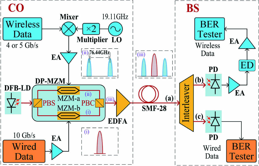
Figure 1 is a schematic diagram of practical verification based on an integrated polarization multiplexing DP-MZM that can generate and transmit independent wireless and wired signals simultaneously. At the central office (CO), a continuous light wave was emitted from a distributed feedback laser diode (DFB-LD) at 1551.7 nm with 10 dBm optical power. Then, it was injected into a polarization beam splitter (PBS). Next, the two optical beams passed through the upper and lower arms and were modulated by an MZM, respectively. Finally, the generated wired and wireless signals were coupled into an optical fiber by a polarization beam coupler (PBC).
Sign up for Chinese Optics Letters TOC. Get the latest issue of Chinese Optics Letters delivered right to you!Sign up now

Figure 1.Schematic diagram of the proposed scheme.
The DP-MZM has a maximum modulation rate of 43 Gb/s, and the PBS and PBC are integrated in one package; two built-in photodiodes (PDs) are used for monitoring each polarization. The 3 dB bandwidth and the polarization isolation of the DP-MZM are 25 GHz and 20 dB, respectively. The insert loss is 6.2 dB.
As for the wired signal generation, it is a 10 Gb/s pseudorandom binary sequence signal that is generated from a pattern generator and has a length of and a peak-to-peak voltage of 0.5 V. Next, the wired signal is amplified by an electronic amplifier (EA) with a gain of 30 dB and a frequency response range of 0–40 GHz. After amplification, the wired signal with the driven voltage of 5Vpp is directly imposed on the MZM-b, which is biased at its quadrature point; as the inset (i) of Fig. 1 shows, at the output of MZM-b, a modulated optical carrier is generated.
Conversely, for the wireless signal generation, a 19.11 GHz sinusoidal wave emitting from a local oscillator (LO) is converted to 38.22 GHz by a frequency doubler and then mixed with a 4 or 5 Gb/s wireless data speed with the same pattern format as the wired data. After mixing, a subcarrier multiplexing (SCM) signal[9] is generated. Then, the SCM signal is amplified by an EA with a 36–41 GHz frequency range and a 30 dB gain. After amplification, the SCM signal with a voltage of 5Vpp directly drives MZM-a, biased at its minimum transmission point. Under these conditions, MZM-a works on the optical carrier suppression (OCS) mode, and two main optical sidebands are achieved by frequency doubling. As inset (ii) of Fig. 1 shows, at the output of MZM-a, the central optical carrier is suppressed, and two main sidebands with a frequency space of 76.44 GHz are generated by frequency doubling, distributed on both sides of the center carrier. So, we can use these two sideband signals to transmit wireless information.
At the output of DP-MZM, as inset (iii) of Fig. 1 shows, the generated optical carrier signals and optical mmW signals are coupled into an optical fiber by a PBC; the output optical power is about 1 dBm. Then, we employ an erbium-doped fiber amplifier (EDFA) to boost the optical power to 11 dBm and send it out through a 15 km SMF-28.
At the base station, a 50/100 GHz optical interleaver is used to separate the optical carriers and the optical mmWs from the received signals. Figure 2 shows the measured optical spectrum of the wired and wireless mixed signals at the input point of the interleaver; we can see that an optical carrier, a pair of optical mmWs, and many undesired sidebands are simultaneously generated.
Figure 2.Optical spectrum of the wired and wireless mixed signals (resolution: 0.01 nm).
The optical spectrum of the separated optical mmW signals, which exit from output (b) of the interleaver, is illustrated in Fig. 3. After filtering, the optical carrier is filled out; we get a pair of optical mmWs of 76.44 GHz as well as other undesired sidebands. The suppression ratio of the mmWs to the other sidebands is larger than 20 dB. Meanwhile, at output point (c) of the interleaver, the optical spectrum of carrier signals is shown in Fig. 4. The ratio of the optical carrier to the sideband is greater than 30 dB. Here, a relatively high carrier-to-sideband ratio is obtained due to the low half-wave voltage of the DP-MZM.
Figure 3.Optical spectrum of the separated mmWs (resolution: 0.01 nm).
Figure 4.Optical spectrum of the separated optical carrier (resolution: 0.01 nm).
Next, the separated optical mmW transmits to a PD with a 3 dB bandwidth of 75 GHz and is converted to an electrical mmW through heterodyne beating. The generated electrical mmW signal is then amplified by an EA with a 75–110 GHz frequency response range. During the following bit error rate (BER) testing, performed to meet the input requirements of the BER tester, we use a W-band envelope detector with a sensitivity of 800 mV/mW and an EA with a 0–30 GHz frequency response to reshape the mmW signals. Another separated optical carrier is directly detected by a PD with a 3 dB bandwidth of 15 GHz and is sent to another BER tester.
Figure 5 shows the eye patterns of wired and wireless signals after back-to-back (BTB) and 15 km SMF transmission, respectively. In the case of BTB transmission, the input optical power into the PD is 0 dBm. From Fig. 5, we can see that following the 10 Gb/s wired signal after 15 km SMF transmission the eye is slightly closed, but no obvious noise is introduced, which shows that good performance is maintained. Conversely, for the 4 Gb/s wireless signal, after 15 km transmission, a little more noise is introduced, and the eye diagram begins to deteriorate. With the transmission rate increased to 5 Gb/s after 15 km transmission, the eye diagram starts to get worse.
Figure 5.Eye patterns of wired and wireless signals after BTB and 15 km single mode fiber transmission, respectively.
Figures 6–8 depict the measured BER curves versus the input power into the PD of the 10 Gb/s wired signal as well as the 4 Gb/s and 5 Gb/s wireless signals after BTB and 15 km SMF transmission. For the wired signal, as Fig. 6 shows, after 15 km SMF transmission, the power penalty of the 10 Gb/s wired signal is about 0.4 dB. There are two main reasons for this circumstance. Because an EDFA is added in the link, a certain amount of amplified spontaneous emission (ASE) is introduced. At the same time, the fiber dispersion of 15 km transmission is also deteriorating the channel. But, we can still realize error-free transmission. As for the wireless signal, from Fig. 7, we can see that after 15 km SMF transmission the penalty at a BER of is around 1.5 dB. This is because of the walk-off effects caused by the two sidebands at 76.44 GHz spacing. We also realized error-free transmission even if over 15 km transmission. When we increase the transmission rate, as Fig. 8 shows, the walk-off effects will further worsen the BER; the penalty is much larger than 3 dB at 5 Gb/s over 15 km transmission. The walk-off effects originate from the fiber dispersion; it makes different velocities of the optical sidebands, causing the edges of the data code to lose synchronization and have a walk-off time[23]. The time shift of the code edge carried by the two main sidebands is , where is the central wavelength of the optical carrier, is the dispersion coefficient, is the velocity, is the RF signal’s frequency, and is the fiber length. For a given code rate of , in our experiment, we use the non-return to zero (NRZ) code format, and the code width is ; if the time shift becomes equal to , the eye diagram will close. Hence, the transmission distance is limited by . According to the parameters of our proposed system, when the wireless signal is at 5 Gbaud, the maximum fiber transmission distance is less than 18 km. In addition, with the increasing input optical power, the saturation effects of the PD begin to appear[24,25], and the saturation effects in the PD will lead to the increased BER. Under this condition, we cannot get error-free transmission; the best BER after 15 km is .
Figure 6.BER curves of 10 Gb/s wired signals.
Figure 7.BER curves of 4 Gb/s wireless signals.
Figure 8.BER curves of 5 Gb/s wireless signals.
In this study, we have proposed and demonstrated a new dual-service transmission system employing an integrated polarization multiplexing modulator. In our experiment, a 10 Gb/s wired signal is directly imposed on the optical carrier, while a 4 Gb/s wireless signal is carried on mmWs of 76.44 GHz, and both kinds of signals simultaneously transmitted 15 km over a single mode optical fiber. For the wireless signal, after transmission, the 15 km SMF has about 1.5 dB power penalty at a BER of , which is due to the walk-off effects of two sideband signals during transmission. By contrast, for the wired signals, the power penalty for the 15 km SMF transmission at 10 Gb/s is around 0.4 dB. This measurement is mainly due to the fiber dispersion and the ASE noise that comes from the EDFA.
Our proposed scheme has the unique merits of simple structure, easy construction, and high reliability, as shown in the following ways. On one hand, because the proposed system adopts a simple modulation to simultaneously generate wireless and wired signals, there is no need to precode or predistort the signals. Therefore, complex digital signal processing for modulation and demodulation is avoided at the transmitter or receiver point, significantly reducing latency and limiting its use to simpler devices. On the other hand, due to the employment of an integrated polarization multiplexing modulator, the two polarization signals are orthogonal, and there is no interference between the two kinds of optical signals during transmission. Moreover, the resolution requirements of the optical interleaver for separating two signals are lower; even if the wired signal and wireless signal cannot be effectively separated, that fact has no obvious effects on the receiver. The experimental results of principle verification show that our proposed scheme is suitable for the next generation of optical-wireless access networks to deliver multiple services.
References
[1] J. Yu, X. Li, W. Zhou. APL Photon., 3, 111101(2018).
[2] T. Kawanishi, A. Kanno, H. S. C. Freire. IEEE Microw. Mag., 19, 102(2018).
[3] B. Wang, L. Peng, P.-H. Ho. EURASIP J. Wirel. Commun. Network, 2019, 118(2019).
[4] B. G. Kim, S. H. Bae, M. S. Kim, Y. C. Chung. J. Lightwave Technol., 37, 6105(2019).
[5] D. Konstantinou, T. A. H. Bressner, S. Rommel, U. Johannsen, M. N. Johansson, M. V. Ivashina, A. B. Smolders, I. T. Monroy. Opt. Commun., 454, 124464(2020).
[6] S. Dang, O. Amin, B. Shihada, M.-S. Alouini. Nat. Electron., 3, 20(2020).
[7] T. Kamisaka, T. Kuri, K. Kitayama. IEEE Trans. Microwave Theory, 49, 2013(2001).
[8] K. Ikeda, T. Kuri, K.-I. Kitayama. J. Lightwave Technol., 21, 3194(2004).
[9] Z. Jia, J. Yu, A. Chowdhury, G. Ellinas, G. Chang. IEEE Photon. Technol. Lett., 19, 1691(2007).
[10] C. Lin, P. T. Shih, J. Chen, P. Peng, S. Dai, W. Jiang, W. Xue, S. Chi. IEEE Photon. Technol. Lett., 20, 812(2008).
[11] W. Jiang, C. Lin, P. Shih, Y. Chen, J. Chen, S. Chi. IEEE Photon. Technol. Lett., 22, 532(2010).
[12] S. Pan, J. Yao, 78(2001).
[13] M. Zhu, L. Zhang, C. Liu, S. Fan, G. Chang, 90(2012).
[14] Z. Cao, H. P. A. van den Boom, C. M. Okonkwo, E. Tangdiongga, A. M. J. Koonen. Opt. Commun., 311, 346(2013).
[15] C. Lin, P. Peng, J. Chen, C. Peng, W. Peng, B. Chiou, S. Chi, 1(2007).
[16] C. Lin, J. Chen, P. Peng, C. Peng, W. Peng, B. Chiou, S. Chi. IEEE Photon. Technol. Lett, 19, 610(2007).
[17] P. Shih, C. Lin, W. Jiang, Y. Chen, J. Chen, S. Chi. IEEE Photon. Technol. Lett., 21, 857(2009).
[18] M. A. Elmagzoub, A. B. Mohammad, R. Q. Shaddad, S. A. Gailani. Opt. Laser Technol., 76, 70(2016).
[19] L. Zhang, X. Hu, P. Cao, Q. Chang, Y. Su. Opt. Express, 20, 14648(2012).
[20] W. Ji, J. Chang. IEEE/OSA J. Opt. Commun. Netw., 5, 127(2013).
[21] Y. Xiang, N. Jiang, C. Chen, C. Zhang, K. Qiu. Opt. Express, 21, 19762(2013).
[22] Y. Jiang, X. Yi, S. Hu, X. Huang, W. Tang, W. Zhou, X. Huang, J. Zhang, K. Qiu. Chin. Opt. Lett., 17, 030603(2019).
[23] J. Ma, X. Xin, C. Yu, Q. Zhang, J. Yu, X. Sang, J. Zeng, 273(2007).
[24] Y. Wang, J. Yu, N. Chi. IEEE Photon. J., 8, 7903209(2016).
[25] Y. Cai, Y. Ling, X. Gao, B. Xu, K. Qiu. Chin. Opt. Lett., 17, 010605(2019).