Alexey Wolf, Alexander Dostovalov, Kirill Bronnikov, Mikhail Skvortsov, Stefan Wabnitz, Sergey Babin. Advances in femtosecond laser direct writing of fiber Bragg gratings in multicore fibers: technology, sensor and laser applications[J]. Opto-Electronic Advances, 2022, 5(4): 210055
Copy Citation Text
In this article, we review recent advances in the technology of writing fiber Bragg gratings (FBGs) in selected cores of multicore fibers (MCFs) by using femtosecond laser pulses. The writing technology of such a key element as the FBG opens up wide opportunities for the creation of next generation fiber lasers and sensors based on MCFs. The advantages of the technology are shown by using the examples of 3D shape sensors, acoustic emission sensors with spatially multiplexed channels, as well as multicore fiber Raman lasers.
Introduction
The emergence of multicore fibers (MCFs) and the subsequent improvement of the technology of their fabrication1-3 gave a powerful impetus for the development of various areas of fiber optics: spatial division multiplexing (SDM) of optical channels in communication lines2, 3, powerful laser systems with coherent beam combining4, 5, microwave photonics devices6, as well as new types of fiber-optic sensors of physical quantities, such as distributed shape sensor7. In scientific research, MCFs are used for studying mechanisms of nonlinear interaction of ultrashort laser pulses8 and for quantum information processing9. Spatial densification of sensitive elements makes MCFs attractive for the fabrication of “lab-in-fiber” sensors performing complex analysis of biological probes10. In the context of fiber lasers, MCF is a promising medium for the development of new schemes of laser sources with improved output characteristics11.
One of the urgent tasks arising when working with MCFs is their structuring — writing of the refractive index structures inside fiber cores such as fiber Bragg gratings (FBGs)6, 12, 13, long-period gratings14, and distributed Rayleigh reflectors15, changing of the fiber diameter due to its tapering16 or cladding etching17, subtractive micromachining for creating hollow regions18, additive micromachining for the deposition of a functional metal and/or dielectric layers on the end face or side surfaces19, and growth of optical elements using the method of femtosecond 2-photon polymerization20.
In this article, we review recent advances in the technology of direct writing of FBGs in MCFs using femtosecond (fs) laser pulses. It is the technology of writing such a key element as the FBG that opens wide opportunities for the development of next-generation lasers and sensors based on MCFs. First, basic information is given on the existing types of MCFs and their features. Next, we compare different methods for writing FBGs in MCFs by using femtosecond radiation. Finally, we consider some types of sensors and lasers based on MCFs, in which FBGs are written by using femtosecond direct writing methods. In particular, we deal with a shape sensor based on a FBG array, as well as an acoustic sensor with spatial division multiplexing of channels. New schemes of Raman fiber lasers based on MCFs are considered, which have a number of advantages over lasers based on single-mode, single-core fibers.
Types of multicore optical fiber
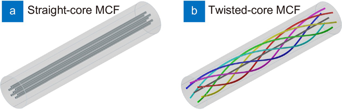
Currently, there is a large variety of MCFs which, depending on the application, have different longitudinal and transverse designs. The main parameters of MCFs include the diameters of core and cladding, the number of cores and their packing geometry, the number of modes supported by the core, the crosstalk coefficient, the presence or absence of twist along the optical axis of the fiber (straight and twisted-core fibers), as shown in Fig. 1. Figure 2 shows examples of typical MCFs manufactured by E.M. Dianov Fiber Optics Research Center (FORC) (Moscow, Russia), some of which are used in our experiments and described in more detail in the following paragraphs: (a) 2-core polarization maintaining fiber (FORC 2-CF-PM), (b) 4-core Yb-doped fiber (FORC 4-CF-YB), and (c–d) 7-core fibers with relatively low and high crosstalk coefficients (FORC 7-CF #1 and #2, respectively).
In particular, for telecommunication applications, both MCFs with weakly coupled (< −30 dB crosstalk) and with strongly coupled cores (> −10 dB crosstalk) are used1. In the first case, it was possible to achieve a record signal transmission rate of 10.66 Peta-bit/s thanks to the use of a 38-core-three-mode fiber21. In the second case, it was possible to achieve a signal transmission rate of 172 Tb/s over a distance of 2040 km by using a strongly coupled 3-core fiber22.
Figure 1.7-core MCFs with straight (a) and twisted (b) side cores.
In the field of fiber-optic sensors, the most widespread MCFs have weakly coupled cores, and have found application in the development of 3D shape sensors7. To create shape sensors, both MCFs with straight and with spirally twisted cores are used, and shape reconstruction is carried out by measuring the FBGs spectra contained in the cores23-25, or by the methods of optical backscattering based on Rayleigh15 or Brillouin reflectometry26. Note that the shape recovery principles used for MCFs can also be transferred to composite optical cables and flexible manipulators, in which single-mode single-core fibers lie outside the neutral bending axis27, 28. See Section Optical sensors based on FBGs in multicore fibers for more details on this topic. Moreover, MCFs can be used as a platform for multiple parameter point sensing29. Indeed, localization of the sensing elements in the longitudinal and transverse directions of the MCF allows for simultaneous spatial and spectral densification when measuring temperature, longitudinal stress, and acoustic impact, as it will be discussed in more detail in Subsection Acoustic emission sensor based on a multicore fiber. In addition to shape sensors, MCFs with strongly coupled cores are used to create various types of sensors: for temperature, deformation, vibration, etc30. As a rule, such sensors are multibeam Mach-Zehnder interferometers, which do not contain additional refractive index structures. Despite their simplicity, the limiting factor in their use is a wide spectral-response characteristic covering hundreds of nanometers.
When creating fiber lasers and amplifiers, MCFs with a large mode area are used both in configurations with weakly coupled cores4, 5, 31 or with strongly coupled cores32, 33. In addition to MCFs doped with such rare-earth elements as Yb and Er, as in the above works, passive MCFs are also used, in which amplification is provided by stimulated Raman scattering induced by pump radiation11, 34. Section Fiber lasers and amplifiers based on multicore fibers is devoted to the development of laser sources of this type.
Femtosecond pulse direct writing of fiber Bragg gratings
The first results on writing FBGs in MCFs were obtained with the holographic method35, and with the method of fiber exposure by laser radiation passed through a phase mask36. In both cases, the MCFs were modified by using UV laser radiation (λ ≈ 250 nm), and the absorption of radiation took place in all cores simultaneously, which led to the writing of FBGs with close resonant wavelengths in each of them. In recent works6, 37 it was shown that the choice of the optimal width of the UV laser beam, as well as the distance between the MCF and the phase mask, makes it possible to achieve the selection of the required side cores when writing the FBG. Nevertheless, this approach is not very practical for the fabrication FBG arrays, in which each of the gratings has individual characteristics (period and profile of the refractive index modulation), since in this case it is required to have a wide set of phase masks, which must be constantly replaced during the writing process.
A new round in the development of FBG writing technology occurred with the appearance of high-power fs laser sources in the visible and IR ranges38. Due to the nonlinear mechanism of absorption of fs pulses, it became possible to modify the refractive index inside the volume of non-photosensitive materials (pure silica, sapphire, fluorozirconate glasses, etc) with a small resolution (~1 μm3)39. This made it possible not only to write FBGs along the selected fiber core40, but also to create waveguides containing Bragg gratings41. In addition, the fabrication of FBGs became possible through a transparent polymer coating of the fiber (acrylate, polyimide, ORMOCER, etc). These advantages have made fs writing methods in demand for the creation of sensors in harsh environments42, as well as for laser systems based on a wide range of materials43, 44. The advantages of fs writing methods especially manifest themselves when modifying optical fibers with a complex transverse geometry, such as multimode and multicore fibers, since they allow not only to select the core and transverse mode45, 46, but also to set an individual geometry for each grating47.
In 2003, Mihailov et al demonstrated the possibility of FBG writing with IR fs laser radiation (λ= 800 nm, Δt = 120 fs, f = 1 kHz, Ep = 300 mJ) in a single-mode fiber by its exposure to the radiation passing through a phase mask48. With this method, a periodic modulation of the refractive index arises because of the interference of ±1 orders of diffraction after passing fs pulses through the phase mask. The FBG period ΛFBG is determined by the period of the phase mask ΛPM, according to the following expression: ΛFBG =ΛPM/2. As it occurs in the case when UV laser sources are used, to reach the material modification threshold, a cylindrical lens is placed in front of the phase mask, which focuses the fs radiation into the fiber core, thereby increasing its intensity. Today, the writing method based on using a phase mask is widely used for the fabrication FBGs in non-photosensitive fibers, as well as when writing FBGs through a protective coating that is transparent to fs laser radiation49. Note that this method is demanding in terms of the energy of fs laser pulses (Ep ~ 0.1–1 mJ), which severely limits the choice of fs laser systems that can be used to write FBGs.
When working with MCFs, fs laser radiation was used to write FBGs through a phase mask in ref.50, where the authors modified all three cores of the passive germanate and active tellurite MCFs. During fiber irradiation, the position of the MCFs was scanned in the transverse plane, in order to increase the region of refractive index modification, and thus to achieve an optimal overlap integral with each of the cores separated by a distance of 30–35 μm. A similar approach was also used by Alon et al in51, where FBGs were written into an active LMA Yb-doped MCF, which contained six 19-µm cores forming a hexagon ring. Note that the requirement for a fiber to be located close to the phase mask makes it difficult to visualize the fs modification region, which complicates the process of writing FBGs in the required core. For this reason, when working with MCFs, direct fs writing methods such as point-by-point, line-by-line, and plane-by-plane ones are especially attractive.
The method of fs point-by-point FBG writing was proposed by Martinez et al in 200440, where the authors focused fs laser pulses of the IR range (λ = 800 nm, Δt = 150 fs, f = 1 kHz, Ep = 100 nJ) directly into the region of the single-mode fiber core with a high-NA objective. In this approach, each “point” of the grating is induced due to the absorption of a single fs laser pulse during the uniform motion of the fiber by using a high-precision positioning stage (Fig. 3(a)). Thus, the FBG period depends on the fiber travel speed vtr and the laser pulse repetition rate f according to the following expression: ΛFBG = vtr/f. If the repetition rate of fs laser pulses is constant, the FBG period can be easily changed by directly varying vtr during the writing of FBG arrays containing gratings with different resonance wavelengths. By specifying the profile of the longitudinal velocity, as well as the transverse position of the fs pulse modification region, chirped47 and apodized FBGs52 can be realized. Controlling an external pulse picker of the fs laser makes it possible to introduce phase shifts into the FBG structure53, 54.
Figure 3.Schematic view of an FBG structure induced in the fiber core with different direct fs writing methods. (a) Point-by-point method (Gaussian beam). (b) Line-by-line method (Gaussian beam with transverse scanning). (c) Plane-by-plane method (astigmatic Gaussian beam).
One of the most flexible and efficient implementations of the point-by-point FBG writing method is the method based on drawing the fiber through a transparent glass ferrule47. With this method of writing, fs radiation is focused through the polished flat face of the ferrule, which makes it possible to minimize aberrations associated with the curvature of the fiber surface. The walls of the capillary channel restrict the freedom of movement of the fiber in the transverse plane, which makes it easier to adjust the position of the fs beam relative to the thin core of the fiber. In the work of Dostovalov et al55 it was shown that, when using a ferrule, it is possible to write FBGs through a polyimide protective coating, and the errors in the positioning of the fs beam focal point arising during the drawing of the coated fiber can be compensated for by using a feedback system. An undoubted advantage of the fs point-to-point writing method is its relatively low requirement for fs pulse energy (Ep ~ 10–100 nJ). Therefore, for the experimental implementation of the method, the choice can be made in favor of cheaper and more compact fs laser systems with an all-fiber scheme. Note that when focusing fs beams with a Gaussian distribution, the modification region is cigar-shaped (Fig. 4(a)), and it overlaps only part of the core of a standard single-mode fiber with a core diameter of ~5–10 μm, which leads to a relatively small value of the overlap integral of the FBG with the mode field of the core. To solve this problem, two modified point-to-point writing methods have been proposed. In the first one, called line-by-line method, a continuous line is formed from the single modification points uniformly distributed in the direction transverse to the optical axis of the fiber56, as shown in Fig. 3(b). Thereby, the FBG period is set by the sequential fiber displacement after each line is written. Despite its best efficiency, the method is less efficient in terms of writing standard FBGs with a length of ~1–10 mm. The second method, called plane-by-plane method, is based on increasing the transverse area of the fs modification region due to beam shaping57. For this purpose, an astigmatic beam is used, which is obtained from a Gaussian beam by placing an additional cylindrical lens in front of the main objective. The proper selection of the focal length of the cylindrical lens, the NA of the objective, as well as the distance between the lens and the objective, makes it possible to increase the modification area in the direction perpendicular to the optical axis, as shown in Fig. 3(c). The advantage of the method is the ability to write high-reflective FBGs with low broadband insertion loss level. In particular, it was shown that the loss level does not exceed 0.02 dB for a 10-mm FBG with a resonance dip amplitude of 25 dB. The disadvantages of the method include a higher requirement for the energy of fs pulses (Ep ~ 1 μJ) than in the case of the point-to-point writing method, as well as the presence of a second focal point, in which the unabsorbed energy of the propagating fs pulse can lead to an undesirable modification of the refractive index (Fig. 4(b)). This feature can affect the crosstalk between the cores, which can be a critical issue when selecting closely packaged MCF cores.
Figure 4.Refractive index change induced by fs laser pulses in the cross section of a single-mode fiber in the case of a Gaussian beam (a) and an astigmatic Gaussian beam (b) for different pulse energies.
In addition to the above-mentioned methods, one can mark out the methods of writing waveguide Bragg gratings (WBGs), by using which both a waveguide and a Bragg grating structures are formed in the volume of the transparent material. Different realizations of the method use fs laser sources with either relatively low (~1 kHz)41 or high (~1 MHz)58 pulse repetition rate. In the first case, the writing of WBG is carried out in two stages. First, a slit or cylindrical lens is installed in front of the focusing lens, resulting in deformation of the Gaussian beam, and a waveguide with a nearly circular cross-section is written. Then the beam-deforming element is removed, and a point-by-point FBG is written in the waveguide. In the second case, the waveguide structure is formed by the continuous irradiation of the slowly moving sample (vtr ~ 0.2 mm/s) with high frequency and low-energy fs laser pulses (λ= 1045 nm, Δt ~ 300 fs, f = 0.1−2 MHz, P ~ 15−75 mW). The Bragg grating is formed by frequency modulation using the AOM, which cuts out pulse trains with a given duty cycle from a continuous sequence of pulses. It is worth noting that at pulse period of ~1 µs, the heat in the focal point region, which arises upon absorption of a single pulse, has no time to dissipate. Consequently, there is a gradual heating of the material until the melting temperature is reached, thus resulting in a refractive index change59. Since the expansion of the heating zone is isotropic, such waveguides have a cross-section, which is close to circular.
Methods of direct fs writing of FBGs have been used in a number of papers to create sensors and lasers. In particular, Donko et al12 performed sequential writing of FBGs in a 7-core fiber with hexagonal-packed cores, by using the point-by-point method. The method was also used in ref.11 to create Bragg mirrors for a Raman fiber laser based on a two-core fiber (FORC 2-CF-PM, Fig. 2(a)). The work of Wolf et al.13 demonstrates point-by-point writing of FBG arrays through an acrylate coating in a 7-core fiber with helically twisted cores. In this case, FBGs writing was carried out using a 1D air-bearing translation stage, and the MCF was drawn through the ferrule, which allows for high-performance writing. This approach was further used in the work of Bronnikov et al25, where a shape sensor was fabricated on the basis of a 7-core fiber with a polyimide protective coating. In this case, an astigmatic beam was used to increase the modification area. The principle of operation of the sensor and the results of 3D shape reconstruction will be discussed in more detail in Subsection 3D shape sensors based on a FBG array in a multicore fiber. The method of fs writing WBGs was used in ref.60 to inscribe helical waveguides in the cladding of a single-mode optical fiber. The authors of ref.61 wrote S-shaped waveguides, in which point-by-point FBGs were written afterwards. The use of waveguides that receive the optical signal from a single core significantly limits the number of FBGs that can be interrogated through the core. This is due to both the loss of the signal in the coupling area, and the limitation on the wavelength division multiplexing of FBGs, which for standard interrogators is ~100 nm.
At present, the technique of FBGs writing while pulling the MCF through the channel of a transparent ferrule (Fig. 5) seems to be among the most flexible and efficient methods — as it provides control of the position of the modification area in orthogonal planes, makes it possible to specify the FBG geometry (period, coupling coefficient, phase shifts, etc), and is suitable for realizing any of the above-described direct fs writing methods. As a ferrule, a glass capillary tube is used, the inner diameter of which has a diameter exceeding the diameter of the fiber by ~5–10 μm. To compensate for aberrations, fs laser radiation is focused through the flat polished face of the ferrule, and the gap between the fiber and the wall of the capillary is filled with an immersion oil. The longitudinal movement of the fiber at a constant speed is provided by a precision linear translation stage, and the rotation angle is set by using the fiber rotator. Generally, when modifying the MCFs, the focal point of the fs beam is set in such a way that it does not pass through the neighboring core. An additional lens, the focus of which is aligned with the main one, allows one to accurately position the selected core relative to the point of refractive index modification.
Figure 5.Focusing the fs laser beam into a selected core of the MCF during FBG writing. (a) 3D view. (b) 2D view in XY plane.
Figure 6.Microphotographs of point-by-point FBGs written individually in the MCF cores. (a) Single FBG in one of the side cores of FORC 7-CF #1. (b) 6 FBGs in the side cores of FORC 7-CF #2.
When working with FBG arrays written in an MCF, one faces the task of independent interrogation of the cores, for which specialized input-output devices (fan-outs) are used. Such a device routes signals from each core to an independent single-core fiber port, or guides signals by using waveguide structures written inside an optical chip. There are two ways for creating such devices. In the first case, a bundle of single-core fibers is collected in a capillary tube and, if necessary, tapered in order to achieve a spatial arrangement of the cores identical to that of the MCF62. In this case, the optical loss at the fan-out conjugated with the MCF is <0.5 dB. In the second case, fan-out is provided by an optical chip with waveguides written using fs laser radiation. The possibility of choosing an arbitrary geometry of the waveguide structures opens up the possibility of fan-out coupling with MCFs with a complex core packing geometry, which is often required in systems with a high data transfer rate 63, 64, as well as in astrophotonic devices65. In particular, one of the latest works demonstrates fan-out reformatting the output of a 120-core multicore fiber into a one-dimensional linear array. Currently, the fs writing technology of waveguides is able to provide the optical loss on fan-out of < 1 dB 64. When working with MCFs with strong cross-coupling between cores, the measurement of FBGs spectral characteristics can be complicated, owing to the nonlinear dependence of the transmission function of an individual core on the wavelength34. In this case, the analysis of the FBG spectra can be performed by precision alignment of the single-mode fiber core with the core of the MCF containing the grating, at a distance which is much less than the coupling length. In particular, this technique is used in Subsection Raman lasing in passive multicore fibers with strongly coupled cores to characterize FBGs written in the FORC 7-CF #2 fiber.
Optical sensors based on FBGs in multicore fibers
Overview
The appearance of MCFs significantly influenced the development of optical fiber sensor systems, which have a number of advantages over their electrical counterparts: compactness, low weight, flexibility, insensitivity to external electromagnetic fields, chemical inertness and radiation resistance7. The transition from a fiber with a single core to a MCF enabled the expansion of the range of measured physical parameters from a standard for fiber-optic sensors (temperature, strain, acoustic wave, refractive index of the external medium, etc.) to transverse pressure, curvature, torsion, and fiber shape. The external disturbance on a certain section of the fiber can be registered by analyzing the transmitted and reflected optical signals, while the spatial resolution depends on the used measurement approach. Nowadays, there is a wide range of measurement techniques that are used: Brillouin, Raman, and Rayleigh backscattering reflectometry, as well as detection of the resonant wavelength of FBGs contained in the fiber. The first three techniques provide distributed measurements, where the spatial resolution usually varies from millimeters to tens of meters, depending on the characteristics of the instruments, such as optical time-domain and frequency-domain reflectometers (OTDR and OFDR). Whereas the interrogated length is determined by signal attenuation, and it can reach up to hundreds of kilometers66. Accordingly, the use of distributed sensing methods provides a longer sensor length and a spatially continuous measurement of parameters; however, the high cost of interrogating devices, relatively long measurement and data processing times limit their use in a number of applications. Detailed reviews of the techniques used for distributed sensing, as well as their practical applications, can be found in the literature66, 67. In the case of using FBGs, sensing is based on measuring their reflection spectra, which have a characteristic resonance width of 0.1−0.5 nm. To realize distributed measurements, an array of closely spaced FBGs is required, the spectral resonances of which do not overlap with each other. Thus, up to 100 FBGs can be allocated in one measuring channel when using a wavelength division multiplexing technique and a standard interrogator device with an operating wavelength range of 1500−1600 nm. Although, with a typical FBG length of ~1 mm, the total length of distributed measurements is severely limited, the possibility of using more affordable optical interrogators with a high interrogation rate (up to ~10 kHz) makes this type of sensors attractive for real-time applications.
When writing FBG arrays, the use of MCFs makes it possible to achieve a denser arrangement of FBGs in the array, due to their separation in the fiber cross-section, in contrast to single-core optical fibers. This advantage can be used in various cases. For example, FBGs written in one cross-section of the MCF, but having different resonant wavelengths, can be used to implement a curvature sensor with one single-mode fiber output13. In this case, the signals reflected from the FBGs in different cores are combined and measured simultaneously. In addition, the independent interrogation of each of the cores allows one to combine at the same point sensors of different types. For example, the bend-insensitive central core can be used for temperature/strain sensing, similar to single-core fibers, and the side cores can contain Fabry-Perot interferometers to measure acoustic impact and the refractive index of the external environment29. In Subsection Acoustic emission sensor based on a multicore fiber, we will take a closer look at the MCF-based acoustic sensor using the SDM technique.
By applying the principle of SDM in MCFs, Zhao et al. demonstrated a multiparameter sensor with simultaneous independent distributed measurement of temperature and acoustic waves over a total sensor length of 5.76 km, where Raman optical time-domain reflectometry was used for temperature measurements, and phase-sensitive optical time-domain reflectometry (φ-OTDR) was used for measuring acoustic effect68. By using different MCF cores, the issue of incompatibility of pump energies for each of the methods was overcome. A similar approach allowed the same authors to localize vibrations with an accuracy of 1 m at a length of 2.42 km, and to measure the frequency characteristics of vibrations with a high signal-to-noise ratio. For this purpose, they used different cores for the φ-OTDR signal and for the signal from the Mach-Zehnder interferometer69.
The unique feature of MCF-based sensors is the possibility of measuring bending deformations, because FBGs written in side cores experience different longitudinal stretching/compression, depending on the position of the core and the value of fiber bending. This result in different FBGs wavelength shifts, which can be used for bending measurements based on sensors calibration. The first bending strain sensor based on FBGs written in a 4-core fiber was proposed in ref.35, where an athermal measurement of bending with a sensitivity of 48.9 pm/m–1 and resolution of ±0.31 m–1 was demonstrated. After that, two-axis bend measurements with FBGs inscribed in a 4-core MCF were shown in ref.36. The development of algorithms for the shape reconstruction of curves from individual measurements of curvature along the fiber made it possible to create 3D shape sensors23, 70, 71 with a high accuracy of shape reconstruction (~1% relative to the sensor length). After these demonstrations of the capabilities of 3D shape sensors based on FBGs inscribed in a MCF or similar configurations (for example, a triplet of single-core fibers on the surface of a tube or fiber bundle), there is a rapidly growing interest in the practical implementation of these sensors. First, they have found applications for 3D shape tracking of flexible medical manipulators, because of the small dimensions of fiber sensors, high multiplexing capability and the compatibility with magnetic resonance (MR) or computed tomography (CT) imaging. The 3D shape sensors based on FBGs in a MCF were developed for shape tracking of multisegmented continuum manipulators72, flexible instruments for endovascular navigation24, continuum robots in minimally invasive surgery73, 74, and flexible needles74, 75. In addition, FBG-based sensors can also be used to measure not only the shape of flexible medical manipulators and instruments, but also for measurements of the tool-to-tissue interaction force at the instrument tip, which is needed in microsurgery, micromanipulation, minimally invasive surgery, such as for example, in vitreoretinal surgery, where high precision of manipulation with controlled force is required to prevent damage of delicate eye tissues. For example, a 3-DOF force sensing pick instrument based on a FBGs triplet with resolution of 0.083 mN and 0.41 mN, with measurements range of ±20 mN and 10 mN for transverse and in axial force measurements, respectively, was demonstrated76. Moreover, MCF-based shape sensors are a promising solution for structural health monitoring28, where high sensitivity to measuring large R values is required. For this purpose, 55 m-long hybrid polycarbonate-silica multicore fiber with outside diameter of 750 µm has been presented, based on three standard 80 µm polyimide-coated fibers with arrays of FBGs inscribed prior to drawing. The measured sensitivity of this sensor is 296 pm/m–1, which is 7 times higher than sensors based on FBGs written in standard 125 µm multicore fibers. It was also shown that FBG arrays inscribed in a MCF can be used for measurements within other types of fiber sensors, in order to monitor various types of impacts (tension, vibration, temperature)77.
There are a number of applications that require the control of a fiber twist for correct shape reconstruction. This is because if the orientation of the fiber coordinate system relative to the laboratory coordinate system varies, the fiber shape reconstruction algorithm will work incorrectly leading to errors in shape reconstruction78. For these reasons, methods for measuring twist based on MCFs with twisted side cores have been proposed79, 80. In this case, the twist of the fiber in the direction coinciding with the direction the side cores twisting leads to strain increase in the side cores, and therefore to a positive FBG wavelength shift in this core; a twist in the opposite direction leads to a negative FBG wavelength shift. Thus, it is possible not only to measure the magnitude of the twist, but also its direction. For example, a fiber twist sensor based on a FBG array inscribed in helically twisted side cores of a MCF with a sensitivity of 8.9 nε/degree-meter was developed in ref.79. A similar approach was implemented in ref.60, where helical waveguide Bragg grating was inscribed in the cladding of a single-core fiber by using the direct fs laser writing method. In this case, the obtained sensitivity was 1.5 pm/(rad/m), while the sensor based on a Mach-Zehnder interferometer that was also formed by helical waveguides in the cladding of optical fibers had a significantly higher sensitivity of 261 pm/(rad/m). It was also shown that the twist sensor with helical side cores has almost two times lower measurement error compared to a MCF with straight cores81. To increase the sensitivity of the twist sensor, a FBG sensor was implemented, consisting of FBG arrays inscribed in single-core fibers and helically-wrapped around an elastic rod82. In this case, the sensitivity of 200 pm/rad/m was obtained, which is several orders of magnitude higher than the sensitivity of a twist sensor based on a standard 125 µm MCF. For more accurate 3D shape reconstruction with a high spatial resolution, a new approach was proposed, consisting of the writing of a continuous FBG array in helical side cores of a MCF with the same wavelength, and interrogating this array by using the OFDR technique15.
3D shape sensors based on a FBG array in a multicore fiber
The detection of external physical impacts on a fiber containing FBGs is carried out by analyzing changes in the reflection spectra of the gratings. For instance, temperature variations and compression/stretching of the fiber lead to a change in the effective refractive index of the FBG and its period, which causes a spectral shift of the reflection peak according to the expression83:
where p is the strain-optic coefficient, ε = Δl/l is strain, Ω is the temperature sensitivity coefficient, and ΔT is the temperature change. When using a standard SMF with the written FBG, it is possible to detect longitudinal strain and temperature variations, but the sensor remains insensitive to bending deformations, since the core is located on the neutral axis of the fiber. However, in the case of MCFs, FBGs written in the side cores not lying on the central axis exhibit bending sensitivity. By using this feature, it is possible to perform fiber shape reconstruction, which is based on measuring the strain ε in individual cores at each point along the interrogated part of the fiber. When the fiber is bent, the cores that do not lie in the neutral plane will experience compression or extension. Besides, according to Eq. (1), applied strain and temperature changes have a joint effect on the FBG resonant spectrum, which does not allow for separating one effect from another without special approaches. A simple solution is to use the measured value of the spectral shift in the core located on the neutral (central) axis of the fiber in order to eliminate thermal effect, as well as longitudinal strain, in order to obtain the ε value associated with bending only. Then for the i-th side core one obtains:
where Δλi, Δλc are the resonant wavelength shifts of the FBG reflection peaks in the side and central cores, respectively, Сi = 1 − pi is determined during calibration, and λFBG,i is the resonant wavelength of the FBG in i-th core in the absence of deformation. The found εi values in the various cores are then used to calculate the curvature vector κ, which, in the case of a symmetrical arrangement of the side cores relative to the fiber center, can be found by using the formula23:
where N is the total number of side cores, rc is the distance between the fiber center and the side cores, nx and nyare unit vectors defining the local coordinate system, and αi is the angle between the direction to the i-th core and the vector nx (see. Fig. 7(a)). When using individual FBGs with a spacing along the fiber which is greater than the length of the grating itself, the measured set of discrete data is usually interpolated. In this case, various methods can be used to obtain a spatial curve representing the fiber shape, such as solving the Frenet-Serret differential equations23, 25, 84, solving the differential equations based on the parallel transport frame85, and the use of transformation matrices24, 74, 86.
Figure 7.(а) MCF cross-section sketch, and relevant parameters for curvature calculation. (b) Schematic representation of the 3D FBG array written in a 7-core MCF through polyimide protective coating.
Due to the intrinsic characteristics of fiber sensors in general, such as small size/weight, flexibility, and chemical/radiation resistance, fiber shape sensors appear to be a promising monitoring tool in harsh environments. For example, MCFs can be embedded in a composite material at the stage of its manufacture, which requires a high degree of adhesion of the fiber protective coating with the glass cladding and with the components of the composite material87, while during the curing process temperatures can reach up to 350 °C88. In another promising application, determining the spatial positioning of a medical instrument in minimally invasive surgery, an important factor is the thermal stability of a MCF with written FBGs during sterilization of the device in an autoclave. At such high temperatures, the acrylate coating of a standard fiber undergoes degradation and destruction89.
Aiming at developing a fiber shape sensor resistant to high temperatures and mechanical stress, we used a custom-made 7-core fiber with a polyimide protective coating (FORC 7-CF #1, see Fig. 2(c)) with the following parameters: protective coating diameter — 154 μm, core-to-core distance — 40.5 μm, and core mode field diameter — 5.7 μm at 1550 nm25. Polyimide coating can be exposed to a prolonged high temperature impact (up to 300 °C), as opposed to acrylate coating (up to 85 °C89), and, relative to the latter, it has better adhesion to the glass cladding and higher mechanical strength. In this MCF, a 3D FBG array was written using the plane-by-plane method (see Section Femtosecond pulse direct writing of fiber Bragg gratings) in the central and three side cores located at the corners of an equilateral triangle. The array consisted of 6 nodes with 4 FBGs in each of them (24 FBGs in total), with a distance between the nodes of ΔL = 14 mm, and a total length of L = 72 mm (Fig. 7(b)). In this case, the FBGs in the same node had the same resonant wavelengths, but in different nodes resonant wavelengths were sequentially varied along the fiber for wavelength multiplexing. In our case, the spectral interval between neighboring FBGs was ~16.7 nm. The sensor was interrogated by using an 8-channel HBM FS22-SI interrogator with a spectral range of 1500–1600 nm through a specialized fan-out compatible with the fiber. The shape reconstruction was performed by solving the system of Frenet-Serret equations.
The created sensor was tested on 2D (loop- and S-shaped curves) and 3D shapes (spirals). In the case of planar shapes, the shape reconstruction error did not exceed 0.2 mm. For 3D spirals (Fig. 8(a)), the deviation from the ground truth curve was about 1.6 mm, or 2.2% relative to the sensor length. In addition, the extreme curvature values that could be possibly measured by the sensor were investigated — from minimum to maximum. With a decrease in the curvature (an increase in the curvature radius), the reconstruction error increases, since Δλ induced by bending becomes comparable with the measurement errors of the device, and the value of FBG birefringence. The obtained results of reconstructing the shape of arcs with a radius R = 100–500 mm indicate the presence of a wavelength measurement error due to the FBG birefringence of Δλp = 20–40 pm, which makes it possible to measure curvature radii up to 350 mm with an error not exceeding 8%, and curvature radii up to 500 mm with an error not exceeding 15%. At the same time, due to the smallness of the L/R ratio, the absolute deviation of the reconstructed curve from the ground truth did not exceed 1 mm or 1.4%. In turn, the minimum measured curvature radius was 2.6 mm with a measurement error of <1%. Even though this radius of curvature is comparable with the FBG length (2 mm), no distortions were found in the reflection spectrum. A stronger polyimide coating with a high degree of adhesion to the glass cladding, compared to acrylate, makes the fiber resistant to multiple bends with small radii.
Figure 8.Result of test shapes reconstruction. (a) 3D shapes − spiral curves with different diameter and pitch (solid − reconstructed curves, dashed − reference curves)25. (b) 2D shape − S-curve, reference curve (solid line) together with reconstructed curves for algorithms based on the Frenet-Serret equations and homogeneous transformation matrices for m = 100 (dashed lines)86. Figure reproduced with permission from: (a) ref.25, (b) ref.86, under a Creative Commons Attribution 4.0 International License
In addition to mechanical durability, it is important to investigate the factors that affect the error of a fiber shape sensor as a measuring device. The accuracy of fiber shape reconstruction depends, among other things, on the distance between the sensing points (FBG locations). Moreover, the total number of points N in the data array determines the computation time, which, with a sufficiently large number of points, may be unacceptable in real-time monitoring systems, despite the high accuracy. To experimentally study this dependence, we measured the shape of a 30 cm long 7-core spun fiber (Fibercore SSM-7C1500) by using a cross-correlation analysis of Rayleigh scattering via OFDR to obtain high resolution, where the number of points used varied during data processing; for shape reconstruction, the Frenet-Serret equations were solved25. While the computation time tincreased as t ~ N or as t ~ 1/dpoint, where dpoint is the distance between neighboring points, the reconstruction error, although it increased monotonically, changed nonlinearly with N, and depended on the specific shape in which the fiber was bent. The results indicate that for these experimental parameters, the maximum reconstruction error did not change significantly, increasing from 2% to 3.3% with an increase in dpoint from 1 to 10 mm, while the computation time decreased by a factor of 10. Thus, a general consideration when choosing the optimal interval dpoint between sensing points is that it should be less than the minimum value of the curvature radius which is expected during operation, which in this experiment was 3–4 cm.
After considering the issue of choosing the interval for the location of the FBG, the next step affecting the accuracy of reconstructing the fiber shape is the interpolation process, namely: the parameters subject to interpolation (strain ε or the modulus of the curvature vector κ (Eq. 3) and its angle relative to the selected coordinate system in which the curve is constructed), the interpolation method, and the resolution, which is the number of interpolating points between adjacent FBG nodes. Jäckle et al. investigated the problem of the choice of parameters for interpolation, and concluded that the best accuracy is achieved when interpolating the measured values of strain ε, since when interpolating curvature and angle, discontinuities may appear in the angular dependence in places with zero curvature, leading to an increase in the reconstruction error24. Henken et al compared various interpolation methods when reconstructing the shape of a medical needle with integrated fiber sensors, and found that the best result in terms of minimizing the error is demonstrated by cubic spline interpolation relative to other methods, such as piecewise linear or polynomial interpolation of various orders90.
The effect of interpolation resolution on the reconstruction accuracy is different for various reconstruction algorithms. While increasing the resolution generally reduces the error, too many intermediate points negatively impact the computation time, which also varies depending on the algorithm used, and can be critical in real-time monitoring systems. In ref.86, an experimental comparison of two algorithms was carried out from the point of minimizing errors and time of shape reconstruction of a MCF: 1) Frenet-Serret equations and 2) transformation matrices. When solving the system of Frenet-Serret equations, the solution is a spatial curve in parametric form. Each point of this curve is associated with a triplet of unit orthogonal vectors that determine the direction of increase in length, direction of bending and change in direction of bending. If there are sections in the curve with zero curvature and abrupt changes in the direction of bending (inflection points), the triplet of vectors at these points cannot be determined unambiguously. As a result, when solving numerically, this can significantly increase the reconstruction error. To achieve acceptable accuracy, the Frenet-Serret algorithm requires a large number of intermediate interpolation points. Cui et al proposed a technique based on the parallel transport frame, devoid of the indicated drawback, where the triplet of vectors remains defined even at points with zero curvature85. However, this approach requires solving differential equations which is similar to the Frenet-Serret case, and it also needs high interpolation resolution in order to get a satisfactory result24. An alternative reconstruction method is to compose a curve from individual arcs with a radius corresponding to the calculated radius of curvature at a given point, and a length equal to the interval between interpolation points. This procedure is performed by using homogeneous transformation matrices.
For the experiments, two samples of shape sensors based on FBG arrays written by the plane-by-plane method (see Section Femtosecond pulse direct writing of fiber Bragg gratings) in a 7-core fiber with a polyimide coating FORC 7-CF #1 (see Fig. 2(c)) were created. Sample #1 was identical to that used in25 and described above. Sample #2 consisted of 9 nodes with an interval of 10 mm, a total of 36 FBGs with an overall sensor length of 82 mm. Spiral, D-shaped, and S-shaped curves were selected as test shapes. Sample #1 was used to measure the spiral and D-shape, and sample #2 was used for the S-shape. The reconstruction was performed for each shape by using both algorithms with the interpolation parameter m(the number of intermediate points between adjacent nodes) in the range from 1 to 1000–5000. The average deviation of the curve reconstructed from the reference one was calculated, and the computation time averaged over 1000 repetitions together with the estimated refresh rate (attainable in the case of a sensor for real-time monitoring) were measured. The reconstructed curves for one of the shapes are shown in Fig. 8(b).
The results show that, for a fixed mean reconstruction error, the performance of the method based on transformation matrices (TM) exceeds that of the method based on the Frenet-Serret (FS) equations for all shapes and samples. Thus the TM method allows for reducing the calculation time up to 70 times (the refresh rate for a specific implementation of the algorithm and the PC used in this experiment is of about 300–400 Hz), which is due to the lower required interpolation resolution. For shapes that have inflection points (D- and S-shapes), i.e., an abrupt change in the direction of bending by 180°, the algorithm based on the FS equations requires an order of magnitude of additional intermediate interpolation points in order to achieve the specified accuracy, which significantly reduces the frame rate down to ~1–10 Hz. Specifically, for the spiral shape, the average error of 0.28 mm (0.4% relative to the sensor length) was achieved at m = 100 for TM, and m = 143 for FS, which results in the estimated refresh rate of 435 and 225 Hz, respectively. At the same time, the D-shape was reconstructed with an error of 0.39 mm (0.5%) at m = 100 for TM, and m = 5000 for FS, which gives the same 435 Hz for the TM algorithm and only 6 Hz for the FS.
A modified algorithm using a similar matrix transformation was proposed by Chen et al, and analyzed using a sensor consisting of 4 SMFs with written FBG arrays glued to the surface of a NiTiNOL memory alloy wire with a square arrangement in cross-section91. In contrast to the standard approach, where the curve is recursively constructed element-by-element by gradually shifting the frame from the starting point common to all elements, the presented method uses fitting of a set of elements with a fixed curvature in order to obtain the final curve. This reduces the accumulated error by an average of 10%, which was shown experimentally by the example of C-shaped, S-shaped, and spiral curves.
As noted above, fiber shape sensors are a promising tool in minimally invasive surgery applications for monitoring the spatial position and configuration of a medical device in a patient's body. To demonstrate the possibility of reconstructing the shape of the moving part of a medical instrument, a shape sensor based on an FBG array in a 7-core fiber with a polyimide coating FORC 7-CF #1 with parameters similar to the aforementioned sample #2 used in ref.86 was introduced into a medical papillotome. The bending of the papillotome tip with the length of about 30 mm and diameter of 1.8 mm was controlled remotely from the other end of the instrument by pulling on the inner string (Fig. 9(a)). The 82 mm fiber section containing the FBG array was positioned in the inner canal of the papillotome, so as to effectively registering the bending of the movable part (Fig. 9(b)). As a result, the error in reconstructing the fiber shape was from 0.1 to 0.8 mm at different degrees of bending: for example, the reconstructed curve for one of the tip positions is shown in Fig. 9(b).
Figure 9.(a) Controlling the bending of the papillotome , and (b) result of the papillotome shape reconstruction with an integrated FBG array written in a 7-core fiber .
Acoustic emission sensor based on a multicore fiber
The capability of spatial division multiplexing can also be used in other types of fiber optic sensors. In this Section we present our results involving an acoustic emission (AE) sensor, which is based on FBG Fabry-Perot interferometers (FBG-FPI) written in different side cores of FORC 7-CF #1 fiber (see Fig. 2(c)) by using the point-by-point method, as described in Section Femtosecond pulse direct writing of fiber Bragg gratings. Each of the used cores contained only one interferometer, based on a pair of 0.6-mm-length FBGs, spaced 26.4 mm apart, with a resonance wavelength near 1550 nm. Thereby the created AE sensor contained three FBG-FPIs (A, B and C) with a center-to-center distance of 77.8 mm, as shown in Fig. 10. A segment of the MCF containing the FBG-FPIs was glued on the surface of a polymer composite material (PCM) plate together with two piezo detectors (PD) (P-A and P-C, respectively), located along a straight line parallel to the MCF at a distance of 275 mm apart. A laser diode with a central wavelength of 1550 nm was used as a narrow linewidth source, and signals from the FBG-FPIs were recorded by using 5-GHz photodiodes (Thorlabs DET08CFC) and a 4-channel oscilloscope (Rigol DS6104), to which the PD was also connected. The oscilloscope operated in the trigger mode with a trigger set on one of the PD channels. Excitation of longitudinal acoustic waves in the composite plate was carried out by hitting the end face of the plate with a metal weight along its plane. A series of hits were made in the direction of the fiber from two opposite sides of the PCM plate at points T1 and T2 (Fig. 10), with several repetitions at each point.
Figure 10.Schematic of an experimental setup for detecting AE in a PCM plate using FBG-FPIs (A, B, and C) written in different cores of the MCF.
Figure 11(a) shows the signals from one of the repetitions in the first experiment, where the AE wave was excited at point T2, all three FBG-FPIs and a single PD (P-C) were used for detection. As one can see, the moment of arrival of the AE wave is localized in time, and differs for individual sensors, which makes it possible to determine the direction of the AE wave propagation. Optical sensors have a longer response time (low-angle front) in comparison with PDs, due to their extended base and lower sensitivity. In addition, the laser wavelength can fall both on the slope and on the minimum/maximum of the spectrum of the interferometer, which determines the direction and the rate of signal change. To test the possibility of quantitative measurements by using the MCF-based AE sensor, an experiment was carried out to measure the speed of a sound wave, where the AE wave was excited sequentially at points T1 and T2, and FBG-FPIs (A and C) were used for detection, together with PDs (P-A and P-C) for comparison. The calculation of the AE wave speed was carried out on the basis of the known distance between the sensors L, and the measured time delay between the edges of the corresponding signals Δt as L/Δt. In order to determine the moment of arrival of the acoustic wave front, it was necessary to find the first point where the derivative of the signal reaches a certain level, greater than the fluctuations of the derivative before the arrival of the acoustic wave. Figure 11(b) shows the derivatives of the signals processed by low-pass filter for one of the repetitions, where the difference in AE wave arrival time between different sensors can be clearly observed. The speed of sound in the PCM, calculated for a pair of interferometers A and C, was 7998 ± 2169 m/s and 7446 ± 1833 m/s for the points of impact T1 and T2, respectively. For a pair of PDs (Р-А and Р-С), the calculated speed of sound was 4802 ± 359 m/s and 5440 ± 131 m/s for points T1 and T2, respectively. The mean value of the speed of sound as it is measured with the FBG-FPIs is greater than the value obtained using the PDs, since fiber interferometers detect longitudinal deformations and, therefore, have maximum sensitivity to longitudinal waves, which have a higher speed than transverse waves, which are detected using PDs. In addition, the data obtained for FBG-FPIs show a significantly larger error. We suppose that this error mainly originates from the statistical error of individual measurements of time delays, whose values are due to the lower sensitivity of the FBG-FPI when compared with the PD (less steepness of the rising edge of the signal). In addition, each section of the fiber, containing the FBG-FPI, was fixed at two points behind the FBGs, while the FBGs themselves and the central part of the resonator remained free to oscillations. It was experimentally found that the eigenfrequency of this mechanical system is ~100 kHz, which corresponds to the characteristic time of its excitation ~10 μs. Thus, the moment of arrival of the acoustic impact can be determined with an accuracy of at least half of the sound wavelength, i.e. ±5 μs.
Figure 11.(а) Signals from FBG-FPI sensors (A, B and C) and one PD (P-C), as well as their variants processed with a low-pass filter, when hitting point T2. (b) The derivatives of the signals processed by a low-pass filter when hitting point T2 for measuring the speed of sound. The yellow area shows the corridor, the crossing of the boundaries of which indicates the arrival of the wavefront in the sensor area; intersection points are shown with vertical dashed lines.
Fiber lasers and amplifiers based on multicore fibers
Overview
Multicore optical fibers (MCFs) are also treated as a perspective medium for high-power fiber lasers and amplifiers, since single-mode fibers with a single core are strongly affected by nonlinear effects at high powers, in particular, by stimulated Brillouin scattering (SBS), stimulated Raman scattering (SRS), self- and cross- phase modulation (SPM and XPM), and modulation instability. Nonlinear effects induce spectral broadening and power conversion to Stokes-shifted wavelengths, thus limiting the output power at the fundamental laser wavelength, as well as distort transverse profile of the beam, as the threshold of a nonlinear process is defined by the local intensity. In order to increase the nonlinear threshold, one should increase the effective mode area Aeff, since the threshold power is proportional to it, e.g. for the SRS process one has Pth_SRS ≈ 16 Aeff/(gR×Leff). In the case of a single-mode fiber, the mode area enlargement is accompanied by a corresponding reduction of refractive index difference between the core and the cladding, which has a minimum value (∆n ~ 10–3), below which a large mode area (LMA) fiber becomes lossy even for moderate bending. Therefore, LMA fibers may only be used in a straightened form, at the expense of the compactness which is inherent to a fiber spool. This means that multicore fibers may be treated as an alternative way of increasing Aeff, which is free of the limitations of single-mode fibers with a single core. In the case of a MCF, each core operates in the single-mode regime, while increasing their number leads to a proportional growth of effective mode area and total power, that may eventually be concentrated in a single beam by the coherent combination of beams coming out from different cores, whenever the phases of individual core beams can be synchronized.
In the case of MCFs with isolated (non-coupled) cores, phase synchronization of individual core modes may be provided by various techniques, for example, by using an active phase controller based on a spatial light modulator and the implementation of a stochastic parallel gradient descent algorithm, for which the experimentally obtained efficiency of combination amounts to 49% with the use of a microlens array4, and up to 68% with the use of diffractive optical elements31. Another option is provided by using an active phase stabilization system based on segmented mirror splitters, lens array and the piezo mounted mirrors5, for which the demonstrated combination efficiency reaches 80 % for an average output power of 70 W and a pulse duration of 40 ps.
At the same time, phase synchronization in MCFs with isolated cores is fraught with problems of in- and out- coupling of radiation to and from individual cores with the use of bulk optical elements, which complicate the optical scheme and require complex alignments. An all-fiber configuration free of these limitations has been obtained with the use of a multimode fiber piece containing a FBG, reflecting all core modes of the 4-core Yb-doped active fiber92, herewith the interference pattern observed in the far-field manifested a phase synchronization of the individual core modes. Besides, phase synchronization has been obtained in a similar MCF with isolated high-index cores in an annular arrangement, where strong coupling between the core modes occurs via the leaky Bragg-like mode in the central cladding area between the cores, which plays the role of mediator93. Such coupling leads to laser generation at the same wavelength for all cores, thanks to the cavity feedback provided for only one core, to which a highly reflective single-mode FBG is connected. In this scheme, the laser linewidth is reduced to 0.025 nm, which is one order of magnitude smaller than the linewidth (0.2 nm) of a single-mode fiber laser with comparable parameters.
MCFs with closely spaced (coupled) cores are characterized by radiation transfer between cores, which leads to intrinsic phase synchronization of core modes. In this case, the radiation propagates along the fiber as a single supermode consisting of coherent core modes with constant phase relations. An all-fiber performance of the multicore Yb-doped fiber laser has been demonstrated in51, where highly-reflective FBGs have been written by fs laser pulses in all of the 6 coupled cores. A slope efficiency of 72.4% and 51.8 W of maximum output power from the laser were achieved. In ref.94 the efficient amplification of the out-of-phase supermode in an active Yb-doped fiber with 7 coupled cores was demonstrated. In a laser based on a 19-core Er/Yb co-doped active fiber with coupled cores, the fundamental in-phase supermode was selected by means of a Talbot interferometer95, which is formed by a piece of a core-free fiber of optimal length with a mirror deposited on its end facet. The implementation of a Talbot interferometer in a multicore ytterbium-doped LMA fiber laser with coupled cores results in the generation of an in-phase mode with 115 W power, the slope efficiency of 61% with respect to the pump power, and the measured M2 value of 1.4332. Moreover, a multicore fiber with coupled cores may be used as a saturable absorber for the generation of ultra-short pulses. In this case, transmission of radiation coupled to the central core of the multicore fiber increases with increasing power, owing to the effect of discrete self-focusing, that will effectively decouple the initial waveguide from its neighbors96. In addition, pulse shortening due to nonlinear spatiotemporal dynamics was proposed theoretically in ref.8 and demonstrated experimentally in ref.97, where 53 fs pulses were obtained from initial 370 fs pulses by exploiting their significant spectral broadening due to self-phase modulation and the subsequent pulse compression in glass block.
Raman lasing in passive multicore fibers with strongly coupled cores
In addition to active MCFs, an attractive approach for high-power fiber lasers involves the implementation of passive MCFs with coupled cores, where amplification and lasing are achieved via the stimulated Raman scattering (SRS) of pump radiation. Similar to active MCFs, multicore structures provide the enlargement of the effective mode area, thus reducing nonlinear effects and therefore reducing spectral broadening when compared with single-mode fibers. On the other hand, interference effects arising from radiation transfer between different cores may lead to an additional line narrowing.
The first demonstration of Raman lasing in a passive MCF was performed for a polarization maintaining 2-core fiber (FORC 2-CF-PM, see Fig. 2(a)) with the length of 550 m34. A half-open cavity of the laser was formed by a broadband fiber loop mirror spliced to the same core in which pump radiation was inserted, and random distributed feedback was introduced via Rayleigh backscattering along the fiber. The laser linewidth at 7 W output power amounts to 0.5 nm, which is >3 times less than the linewidth of a similar random Raman fiber laser based on a conventional single-mode PM fiber of the same length (1.8 nm) 34. It has been shown that the relative line narrowing in a 2-CF when compared with SMF is defined not only by the reduction of nonlinear effects due to the enlargement of effective mode area, but also by the spectrally selective features of the 2-CF, arising from coupling induced interference. A replacement of the fiber loop mirror in the half-open cavity of this Raman laser by one or two fs pulse written FBGs in one or two cores, respectively11, resulted in a more stable generation regime, for which the spectral shape of the laser line remains unchanged in the long term. This is in contrast to ref.34, where interference-induced line narrowing was sensitive to the environment, thus leading to an instability of the output spectrum. In addition, the half-open cavity based on in-core FBG(s) provides additional spectral effects. For the selective inscription of a FBG into an individual core of the 2-CF, a method of point-by-point femtosecond writing by means of fiber drawing through a ferrule was used (see Section Femtosecond pulse direct writing of fiber Bragg gratings and Fig. 5). The narrowest and most stable line was obtained for a random laser scheme with a single FBG at the pump input — its width varies only slightly between 150 and 200 pm in the power range of 1–3.5 W, with a tendency to saturation. Two FBGs written in different cores with an axial shift of about 5 mm form a Michelson-type interferometer in the coupled cores. As a result, the laser spectrum near the generation threshold (at output power of ~10 mW) exhibits an interference-induced multi-peak structure with the width of individual peaks narrower than the optical spectrum analyzer resolution (~20 pm), thus offering new opportunities of spectral filtration in MCF-based lasers.
As a next step, Raman lasing in passive MCFs with increased core number was explored. A scheme of such Raman laser based on a 7-core fiber with strong optical coupling of the cores (FORC 7-CF #2, see Fig. 2(a)) and linear cavity based on in-core FBGs is shown in Fig. 12(a).
Figure 12.(a) 7-core fiber Raman laser scheme. (b) Reflection spectra measured for FBGs written in the side cores of the MCF. The inset shows the cleaved end of the MCF fiber used in the experiments.
The pump radiation of an Yb-doped fiber laser with a wavelength of 1050 nm and power of up to 17.5 W was launched into the central core of a 7-core fiber (L = 1040 m) through a WDM coupler operating at 1050/1090 nm. High-reflectivity (R > 90%) FBGs with a resonance wavelength of 1090 nm, nearly corresponding to the Stokes wavelength, were written in all the side cores close to both ends of the fiber spool (see Fig. 12(b)). The outcoupling FBGs were shifted relative to each other along the fiber at a random distance in the range of 5−10 mm. The pump radiation was coupled through a single-core single-mode fiber (SMF) spliced to the central fiber core, which has no FBG. This allowed one to avoid non-resonant pump losses in the input FBGs. To separate pump light from the SRS signal, a Thorlabs GR50-1210 diffraction grating was used. Thus, the output light had the form of 14 spatially separated beams, and a diaphragm was used to isolate each of them in spectral measurements. The laser output spectra were measured by using a Yokogawa AQ6370 optical spectrum analyzer (OSA) with a resolution of 20 pm. The beam profiles were measured using Thorlabs M2MS-BP209 beam profiler. The output power at the pump and generation wavelengths were measured by Coherent FieldMaxII power meter. The spectrum and power from the central core in backward direction were measured through the 1090 nm port of the WDM coupler.
In Fig. 13 we show the evolution with input pump power of the output power for the Stokes wave co-propagating (forward Stokes) and counter-propagating (backward Stokes) with the pump light, and the transmitted pump power, respectively. Solid lines show the results of numerical simulations for both Stokes generation and residual pump power. Since the configuration involves a symmetric resonator (in terms of reflection coefficient), the numerical values for the output powers of the Stokes components coincide. The simulation parameters are the following: the effective reflection coefficient for the input and output FBGs are Reff ≈ 85%, losses at the pumping and generation wavelengths are αs = αp ≈ 1.1 dB/km, the effective coefficient of the Raman gain is gR ≈ 0.16 W–1 km–1, which takes into account the enlarged effective area, owing to the strong coupling of individual core modes. This coupling leads to equal redistribution of the pump and the Stokes radiation among all cores. As a result, the lasing threshold of the Raman fiber laser was reached at the relatively high pump power value of 3 W, which corresponds to the increase in the effective mode area for the coupled cores. The transmitted pump power is additionally reduced, owing to nonresonant losses at the output FBGs, which are taken in the model to be about 3 dB to fit experimental points. The total output Stokes power (from all the fiber cores and from both ends) at a maximum pump power of 17.5 W is about 5 W both in simulations and experiments.
Figure 13.7-core Raman fiber laser power characteristics: output power of the backward Stokes (■), forward Stokes (●) and transmitted pump power (♦) as a function of input pump power. Red line is the result of numerical simulations for Stokes generation, blue line − numerical simulations for transmitted pump power.
In Fig. 14(a) we present the backward Stokes wave spectra from the central core as a function of output power. With increasing power, the laser emission linewidth increases, which is a characteristic of single-core fiber Raman lasers as well: this is due to the influence of nonlinear effects (self-phase and cross-phase modulation) on the laser linewidth11. The increase of the effective mode area due to core coupling reduces the influence of nonlinear effects, owing to the reduction in the nonlinearity coefficient, which leads to a decrease in the laser emission linewidth. For output powers of 0.01, 0.5, 1, 1.5 W, the –3 dB width is 30, 70, 170, 220 pm, respectively. At a maximum output power, the FWHM does not exceed 270 pm. Note that the modulation induced by interference effects between beams reflected from output FBGs with different axial shifts and then coupled within the beating length (thus forming Michelson type interferometers) is important near the threshold, whereas its influence becomes weak at the maximum power. The irregularity of peak distance observed at low powers is ascribed to the fact that multiple interferometers with random base length are formed here, in contrast to only one interferometer formed in a 2-CF with coupled cores, resulting in a regular multi-peak structure as reported in Ref.11.
Figure 14.(а) Backward Stokes wave spectra of the central core. (b) Forward Stokes wave spectra of the central and two side cores at the maximum input pump power.
The measured spectra of the forward Stokes wave emerging from the central core have similar shapes. Whereas Stokes wave spectra from the side cores are quite different. Fig. 14(b) compares the spectra of a Stokes wave from central and side cores co-propagating with the pump at maximum input pump power. The central part of the spectra (1090 nm) from the side cores has a dip, owing to the high-reflective FBG at this wavelength. At the same time, the transmissions of different output FBGs are different, due to the slight variation of their central wavelengths and reflection coefficients.
The output beams from different cores measured by the beam profiler at the maximum pump power are shown in Fig. 15. In contrast to the pump radiation profile, which is distributed nearly equally between the cores, for the Stokes lasing, the main power is concentrated in the central core due to the absence of a FBG in it. The Stokes beams coming from side cores are weak because of FBG reflection, except for one which exhibits a significant power leakage (because of the nonoptimal output FBG in this core). At the same time, the relative value of the leaked power reduces as the Stokes power grows larger.
Figure 15.The output beams from different cores measured by the beam profiler at a maximum pump power. (a) Unabsorbed pump. (b) Forward Stokes wave.
Thus, a Raman laser generating at the wavelength of 1090 nm with total output power up to 5 W (2.5 W in each direction) based on a 7-core passive fiber with coupled cores, in which FBGs with specified transverse and longitudinal positions are written in individual cores by fs pulses, has been demonstrated. Along with the Stokes line narrowing induced by the reduction of spectral broadening via nonlinear effects, owing to the enlargement of effective mode area in the multicore fiber with coupled cores in comparison with a standard SMF Raman laser, the additional line narrowing effect induced by the multicore random FBG array was also revealed. As a result, the generation of a single peak of 20−30 pm linewidth (nearly corresponding to OSA resolution) near the threshold (at the Stokes power of ~10 mW) was obtained; whereas the linewidth broadens to ~250 pm at maximum power. It should be pointed out that the single peak generation at low powers is not stable enough, since it exhibits temporary conversion to multiple 20 pm peaks with random spacing and amplitudes, defined by the interference of beams reflected from individual output FBGs with random longitudinal shifts.
Conclusions
The femtosecond technology of refractive index modification inside transparent materials offers a high degree of freedom when operating with MCFs. In the context of FBGs, this freedom is expressed in the selection of a strictly defined core, as well as in the specification of geometric and spectral properties for the FBGs. In addition, the femtosecond writing technology makes it possible to create additional waveguide structures inside a MCF, as well as to carry out its additive and subtractive processing. This, in turn, allows the technology to be used to create complex optical integral elements for SDM communications, components for measuring physical quantities and biosensors, as well as complex sets of Bragg mirrors for laser systems.
To date, the research and development of fiber sensors of curvature, torsion and shape demonstrates high measurement accuracy when using various methods, which are most appropriate for each case. The next steps in their development will be focused on combining the best solutions in terms of balance of accuracy, performance and cost in a single device. In addition to shape reconstruction, it is promising to add other independently measurable distributed parameters such as temperature, vibration, pressure, etc. In this regard, MCFs provide an efficient platform because they combine independent optical channels into a single compact fiber.
Multicore fiber lasers with intracore FBGs demonstrate interesting spectral features, resulting from the effective mode area enlargement and interference effects arising from the coupling of radiation reflected from FBGs inscribed in different cores. Another interesting opportunity is provided by the combined use of random arrays of highly-reflective FBGs distributed between the cores of 7-core fiber, and of arrays of weak FBGs randomly distributed along each fiber core, similar to that used for line-narrowing in single-mode fiber Raman laser98. A further increase of the core number in active and passive fibers and corresponding number of FBGs inscribed into the cores would be of interest for both power scaling as well as for line narrowing. For the sake of power scaling of both conventional and Raman-type amplifiers and lasers based on active and passive MCFs, respectively, it is especially important to explore the possibility of pump coupling into the fiber cladding, similar to conventional high-power single-mode fiber lasers using a double-clad fiber structure.
References
[3] Tang M. Multicore fibers. In Handbook of Optical Fibers 895–966 (Springer, 2019); http://doi.org/10.1007/978-981-10-7087-7_37.
[21] Rademacher G, Puttnam BJ, Luís RS, Sakaguchi J, Klaus W et al. 10.66 Peta-Bit/s transmission over a 38-Core-three-mode fibeR. In 2020 Optical Fiber Communications Conferenceand Exhibition (OFC) 1–3 (IEEE, 2020);http://doi.org/10.1364/OFC.2020.Th3H.1.
[22] Rademacher G, Luís RS, Puttnam BJ, Ryf R, Van Der Heide S et al. 172 Tb/s C+L band transmission over 2040 km strongly coupled 3-core fiber. In 2020 Optical Fiber Communications Conference and Exhibition (OFC) 1–3 (IEEE, 2020);http://doi.org/10.1364/OFC.2020.Th4C.5.
[27] Ryu SC, Dupont PE. FBG-based shape sensing tubes for continuum robots. In 2014 IEEE International Conference on Robotics and Automation (ICRA) 3531–3537 (IEEE, 2014);http://doi.org/10.1109/ICRA.2014.6907368.
[30] May-Arrioja DA, Guzman-Sepulveda JR. Fiber optic sensors based on multicore structures. In Fiber Optic Sensors (eds. Matias IR, Ikezawa S, Corres J. ) 347–371 (Springer, 2017);http://doi.org/10.1007/978-3-319-42625-9_16.
[62] Watanabe K, Saito T, Imamura K, Shiino M. Development of fiber bundle type fan-out for multicore fiber. In 2012 17th Opto-Electronics and Communications Conference 475–476 (IEEE, 2012); http://doi.org/10.1109/OECC.2012.6276529.
[75] Abayazid M, Kemp M, Misra S. 3D flexible needle steering in soft-tissue phantoms using Fiber Bragg Grating sensors. In 2013 IEEE International Conference on Robotics and Automation 5843–5849 (IEEE, 2013);http://doi.org/10.1109/ICRA.2013.6631418.
[79] Askins CG, Miller GA, Friebele EJ. Bend and twist sensing in a multi-core optical fiber. In LEOS 2008 - 21st Annual Meeting of the IEEE Lasers and Electro-Optics Society 109–110 (IEEE, 2008); http://doi.org/10.1109/LEOS.2008.4688512.
[88] Yang SY, Ji M. Polyimide matrices for carbon fiber composites. In Advanced Polyimide Materials 93–136 (Elsevier, 2018);http://doi.org/10.1016/B978-0-12-812640-0.00003-2.
Alexey Wolf, Alexander Dostovalov, Kirill Bronnikov, Mikhail Skvortsov, Stefan Wabnitz, Sergey Babin. Advances in femtosecond laser direct writing of fiber Bragg gratings in multicore fibers: technology, sensor and laser applications[J]. Opto-Electronic Advances, 2022, 5(4): 210055