
Marco Seminara, Marco Meucci, Fabio Tarani, Cristiano Riminesi, Jacopo Catani. Characterization of a VLC system in real museum scenario using diffusive LED lighting of artworks[J]. Photonics Research, 2021, 9(4): 548
- Photonics Research
- Vol. 9, Issue 4, 548 (2021)
Abstract
1. INTRODUCTION
Light-emitting diodes (LEDs) have progressively replaced conventional light sources in most indoor and outdoor illumination systems. The breakthrough empowering LED-based illumination dates back to the achievement on the efficient large-scale production of blue GaN-based LED substrates [1], as white light can be generated by shifting part of the blue component to the green-red part of the spectrum through an additional layer of phosphors. Besides offering higher energy efficiency and brilliance as compared to conventional sources, LEDs feature a fast modulation bandwidth together with a large optical intensity, hence sparking intense scientific research and industrial activity in visible light communication (VLC) technologies [2–4].
VLC aims at providing for wireless connectivity alongside illumination using ordinary LED sources by encoding information inside the optical carrier through high-frequency modulation of optical intensity, which is not perceived by the human eye.
In contrast to the standard radio-frequency (RF)-based wireless communication protocols, such as WiFi, Bluetooth, near-field communications (NFCs), cellular networks, and other Internet of Things (IoT) communication networks [5,6], where the information is encoded in a carrier whose frequency falls in the regulated RF or microwave range, the optical carrier used by VLC lays in the hundreds of terahertz (THz) range, so the theoretical limit for bandwidth is orders of magnitude higher.
Sign up for Photonics Research TOC. Get the latest issue of Photonics Research delivered right to you!Sign up now
Ultrahigh-bandwidth VLC implementations, with data rates exceeding the 3 Gb/s range, have been demonstrated in specific configurations with small-area, monochromatic blue micro-LEDs [7,8], while short-range VLC implementations using high-power white LEDs feature bandwidths exceeding 1 Gb/s [9,10]. The latter kind of implementation, particularly relevant as it employs white sources suitable for illumination and ambient lighting, generally suffers from a reduced transmitter bandwidth for a twofold reason. First, high-power LEDs with optical power above 10 W are typically embedding substrates with large area, with a large intrinsic parasitic capacitance. The typical bandwidth of phosphorus-based LEDs is around 2 MHz [11], orders of magnitude less when compared to monochromatic LEDs of the same size. Second, the fluorescent conversion process of blue light, required to generate a white spectrum, features a finite lifetime that limits the practically achievable bandwidth on the transmitter side. Nevertheless, recent works show that it is possible to use optical filters to isolate only the blue component of the spectrum, reaching the typical bandwidth of monochromatic LEDs at the expense of total received power [12]. Other advantages of VLC stem from the possibility to avoid RF radiation for establishing wireless connections, making VLC practically unharmful for humans and suitable for integration in sensitive environments such as hospitals, airplanes, or heavy industrial settings where the standard RF-based communication is inappropriate due to excess electromagnetic interference (EMI). Another key aspect of VLC is related to the intrinsic spatial directionality of the optical channel. Since the light field can be more easily contained by walls or more easily shaped as compared to an RF field by relatively easy-to-implement and low-cost optical elements, VLC represents a prominent candidate for the deployment of localization protocols for users and visitors in indoor environments, especially in cooperation with an RF-based uplink exploiting, e.g., WiFi networks [13] or the much more complex LiFi attocell networks [14].
Given the intrinsic features of VLC, especially the possibility to establish directional links, an extensive deployment of such technology would open up a wealth of revolutionary applications toward a full-fledged smart community scenario, e.g., through urban mobile crowd sensing in the field of intelligent transportation systems (ITS) [15] or in the retail sector, to provide customers with quick access to desired products [16]. One of the most promising applications is to be found in museums and cultural heritage sites, where visitors standing in front of artwork would consistently benefit in terms of user experience by obtaining dedicated, real-time information on the specific work they are staring at. To this scope, the characterization of a VLC system in a relevant museum environment, employing real lighting systems that illuminate real artwork, would be essential to validate the ability to deploy the VLC technological platform. In particular, it would be crucial to demonstrate the feasibility of employing light diffused by artwork (e.g., paintings or wall paintings) to reliably transmit information and to provide a characterization of the optical wireless channel in terms of packet error rate (PER) as a function of position, relative angle, and distance from the artwork.
However, despite basic preliminary works for museum applications [17,18], mainly aimed at the demonstration of proof-of-principle electronic guides in a laboratory environment [19] or for surveillance and security reasons [20], no such study has been reported to our knowledge, so the suitability of VLC implementation in museum environments remains substantially unproven.
In this work we perform an extensive experimental campaign in the Basilica of Santa Maria Novella (SMN) in Florence (Italy) aiming at a detailed characterization of the performance in a real museum environment of a novel VLC system. Our VLC prototype exploits the existing LED-based lighting system that illuminated artwork in the Basilica to cast digital information along with the illumination onto several paintings, including masterpieces by Masaccio, Vasari, and Ligozzi. By means of non-line-of-sight (NLoS) transmission tests on several masterpieces, we demonstrate for the first time the possibility for an observer, placed in front of a specific artwork (either wall painting, wood painting, or canvas) to reliably receive digital information through the light diffused by the artwork. We assess the transmission performances of the system by performing PER analysis as a function of relative distance and angle between the receiver and each of the artworks, also quantifying the effect of angular misalignment and lateral shifts. Our results show that a reliable NLoS and diffusive VLC data transmission can be achieved for distances from the paintings up to 6 m and view angles as large as 60°, at baud rates of 28 kbaud.
Moreover, we demonstrate that, in a real configuration, a proper tuning of the field of view (FoV) of the receiver stage may restrain the received data to that diffused by a specific hot spot, making our setup virtually capable of distinguishing data streams cast by nearby spotlights. As outlined earlier for line-of-sight (LoS) configurations [20], this feature is very relevant as it would enable the effective indoor localization of visitors standing in front of a specific artwork, e.g., by simply providing the system with an additional cooperative RF-based uplink [13,18].
The rest of the paper is organized as follows. In Section 2 we describe the VLC system, in Section 3 we describe in detail the experimental campaign performed in the Basilica of SMN and we report and discuss the results of our measurements campaign, while in Section 4 we give conclusions and outlooks on our work.
2. Tx-Rx HARDWARE DESIGN
A. Hardware Overview
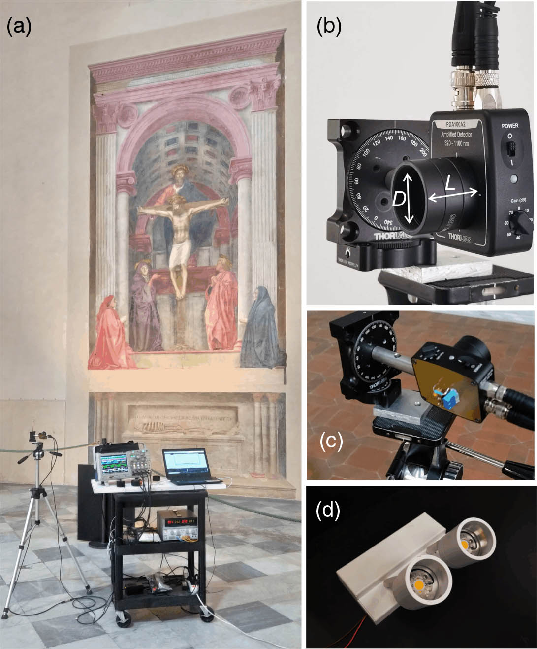
Figure 1.(a) Example of test setup for VLC links in museum environment; (b) and (c) receiving stage; (d) the LED lamps used for VLC transmission.
1. Transmitter
The modulation signal is generated by a digital encoder based on an open-source digital microcontroller board (Arduino DUE). This is obtained via an interrupt-based control of in-out ports of the board, exploiting the 84 MHz clock of the DUE controller, with a minimum observed resolution of in the generation of the Tx waveform. The Manchester encoding guarantees a constant average signal leading meanwhile to a constant illumination of artwork, with the drawback of halving the effective bit rate of the communication chain. The modulation signal is fed into a custom power stage (see Ref. [21] for further details), which adds an AC modulation on top of the DC supply current (0.7 A) required by the LED lamp so that the modulation signal is translated into a corresponding LED intensity modulation. Similar to what is done in recent outdoor intelligent transportation systems implementations [22], we perform a 0%–200% modulation of the LED current so as to maximize the modulation intensity while preserving the overall nominal intensity. This configuration seems to have no negative consequences on the LED’s lifetime after months of regular operations.
2. Receiver
The Rx unit collects the light cast by Tx and diffused by the artwork on a transimpedance photodiode with variable secondary-stage gain (Thorlabs PDA100A2). However, the photodetector is hard-modified by insertion of an AC-coupling network before the first transimpedance stage [21]. This helps to suppress spurious DC stray light components (such as sunlight or other artificial illumination sources) so that the gain value of the amplification stage can be increased to high values (up to ) with no risk of saturation, as only the small signals corresponding to the modulation component are retained. The amplified analogue signal is then digitized by a threshold comparator stage and decoded by a second digital board (based on the Arduino DUE platform as well). The message is bitwise compared to a predefined message to perform PER analysis in real time. In order to provide a tailored limitation to the detector’s FoV, which exceeds 110° in the case of bare photodiode, we have inserted an aperture stop realized through a coaxial tube [Fig. 1(b)]. The diameter and length of the tube are 25 and 20 mm, respectively. Such implementation gives an optical angle of FoV of the Rx stage of approximately 60°, yielding a transverse linear FoV of roughly 5 m at a distance of 4 m. This configuration is optimized to the specific case of SMN paintings’ layouts, where the artwork’s dimensions exceed with a minimum side spacing of 5–10 m. Such layout, indeed, allows the Rx stage to collect a large portion of the light diffused by the painting, yet it strongly limits the effects of possible interference due to angled rays coming from nearby VLC hot spots (see Section 3).
B. Transmission Protocol and PER Analysis
The Tx stage encodes information in the optical carrier through the current modulator. The data packets are composed by a 3 byte equalization frame, followed by a 2 byte synchronization preamble and a 4 byte data payload. The chosen modulation scheme is an on–off keying (OOK) scheme with Manchester encoding [23] as recommended by IEEE 802.15.7 PHY 1 for VLC [24].
Although our system is capable of attaining larger baud rates in the case of a direct LoS configuration [22], in our measurement campaign we chose to employ a 28 kbaud rate. Higher baud rates would indeed require a lower gain at the Rx stage to increase the electronic bandwidth of the Rx stage, limiting de facto the attainable VLC cast to few meters, which is insufficient to cover the typical security distance from masterpieces required in real museum environments (see also Section 3.C). PER is chosen as the relevant metric for our campaign because, different from bit error rate (BER: the number of bit errors over the total number of transmitted bits), it is directly linked to the quality of services that can be implemented and to the expected latency [25]. PER is calculated by definition as , where is the number of received packets featuring at least one wrong bit in the data payload, and is the total number of received packets showing correct preambles. In our campaign, we perform the PER analysis by recording a continuous stream of data packets, which are analyzed in real time, bitwise by the Rx digital stage. The pre-equalization frame is not analyzed. It has the main purpose of stabilizing the packet signal toward its steady root-mean-square (RMS) value, around which the comparator threshold is set. The total acquisition length, limited to packets due to finite time allowance for the measurement campaign in SMN, sets the minimum detectable PER to in the case in which no errors are detected.
3. MEASUREMENT CAMPAIGN
A. Measurements Overview
![]()
Figure 2.Sketch of the experimental campaign. A custom detector is placed at various distances/angles from a specific artwork. The three panels represent different measurement configurations: (a) polar measurement, (b) FoV characterization, and (c) evaluation of lateral shift influence. The centered configuration is obtained aiming the detector’s optical axis toward the geometrical center of the painting; in the flat configuration the detector’s optical axis is parallel to the floor.
B. Amplitude Maps
The quality of a transmission channel is intimately connected to the signal-to-noise (SNR) ratio as measured on the detected signal at Rx stage. Assuming a given integrated RMS amplitude noise value , the SNR value is given by , depending linearly on the recorder RMS amplitude value . In turn, for OOK modulation, under the additive white Gaussian noise approximation, we can link the measured SNR to the expected error probability in the transmission via the function [26], yielding
![]()
Figure 3.Experimental SNR maps recorded for (a) Trinity—a wall painting by Masaccio; (b) Resurrection with Four Saints—a canvas by Vasari, and (c) St. Raymond of Penyafort Resurrects a Child—a wood painting by Ligozzi. Data are taken in both centered and flat configurations (see text). Black dots represent the actual measurement grid, whereas the color maps show a heuristic spline interpolation to the data.
Our data highlight several interesting features. First, the recorded intensity strongly depends on the specific artwork in both the flat and centered configurations. Considering the centered case (right panels of Fig. 3), given a practically constant illuminance of paintings by the LED lamps, the first reason for such variation resides in the different nature and chromatic composition of the paintings. The Trinity wall painting by Masaccio (a) has a rough surface favoring a strong diffusion of the light toward the observer; in addition, the painted layer is faded by time and environmental factors, so light absorption is limited. In the case of Ligozzi’s wood painting (c), the marked smoothness of the wooden substrate, in association with the darkness of employed pigments and to the relevant reflectivity of the painted layer, strongly decreases the global amount of light collected by the detector. The canvas by Vasari (b) features intermediate brightness of pigments and a more pronounced roughness of the painted surface with respect to the (b) case, and it hence features an intermediate overall diffusion of light toward the Rx stage. The wall painting (a) features the largest diffused intensity, with a maximum SNR of 21 dB when facing the painting at a distance of 4 m, to a minimum SNR of 15 dB at 6 m and 60° view angle. The lowest diffusion is provided by the wood painting (c), where the SNR spans from 16 to 8 dB. As a reference value, specializing results of Eq. (1) to our system, we highlight that a PER value of is obtained for SNR = 20 dB, while SNR = 15 dB grants PER = 0.1. In the flat case (central panels of Fig. 3), the global diffused intensity appears generally higher than in the centered case. Assuming a uniform illumination of the surface and a Lambertian emission pattern for the diffused light from the surface [27], this behavior is expected, as the maximum diffusion line coincides with the orthogonal direction with respect to the painting’s surface. As the relative angle between the normal direction and optical axis of the Rx stage is increased (see Fig. 2), as in the centered configuration, the illuminance value of the diffused light at the detector’s aperture decreases with respect to its maximum value. It is also interesting to compare two different relevant positions on the polar grid leading to the maximum and minimum SNRs, which are located at (4 m, 0°) and (6 m, ) and defined as frontal and angled, respectively. The recorded SNR values for such positions are presented in Table 2. While for the (a) wall painting case the difference in SNR between frontal and angled is below 7 dB for both the flat and centered configurations (see Table 2), such difference is much higher in both the (b) and (c) cases. Particularly striking is the case of the flat configuration, where the difference in SNR between frontal and angled exceeds 14 dB in the (b) case. The reason has to be addressed to the presence of white, bright altar clothes, set in front of both the Vasari and Ligozzi masterpieces, which are producing a strong diffusion component of the light toward the detector in the flat case, when the optical axis of the Rx is horizontal. Such component has a much lower effect (if not negligible) in the centered configuration, as the finite FoV of the detector makes only the central portion of the paintings contribute to the VLC signal due to the finite FoV of the Rx stage (see Section 2.A.2). Measured SNR Values in Relevant Positions in Front of the Three Artworks Frontal and angled viewpoints correspond to (4 m, 0°) and (6 m, Flat Centered Frontal (dB) Angled (dB) Frontal (dB) Angled (dB) (a) Masaccio (wall painting) 22 17 21 15 (b) Vasari (canvas) 23 9 19 10 (c) Ligozzi (wood painting) 20 8 16 8
Our measurements show that our Rx stage can attain large SNR values in a large area surrounding each artwork. This is also due to the possibility of using high transimpedance gain without DC saturation effects (see Section 2.A.2), which leads to high SNR values on the whole measurement grid, allowing, as a consequence of Eq. (1), an overall low PER.
C. VLC Transmission Performances: PER Measurements in a Radial Configuration
Validation of the VLC prototype system in real museum settings requires a thorough experimental characterization of VLC transmission performances in different positions of the Rx on the grid, which should correspond to reasonable positions (distances and radial angles) of an observing visitor. In our campaign we perform PER measurements using the same experimental grid and configuration employed to collect SNR amplitude maps [see the previous section and Fig. 2(a)]using a baud rate of 28 kbaud. We have chosen such value after an initial test ranging from 4.8 to 115.2 kbaud, as best trade-off between bit rate, cast, and view angles attained by the VLC system. Using a higher baud rate would increase PER to unacceptable values for a reliable transmission, while using a lower baud rate would increase the latency values, giving on the other hand an error-free transmission for much larger values of distance and view angles. The latter feature does not necessarily represent an advantage for VLC museum applications, as the Rx would very easily receive and decode VLC signals emitted by nearby artwork. This would make the VLC wireless channel poorly directional and hence unsuitable for localization of visitors in front of specific VLC hot spots.
![]()
Figure 4.PER maps as a function of the radial angle for the three artworks measured at distances of 4 and 6 m: (a) wall painting by Masaccio; (b) canvas by Vasari; (c) wood painting by Ligozzi. The dots represent the experimental data, with a statistical average error (where not shown the error bars are masked by symbol size). The lines are a spline interpolation placed as a guide to the eye. The green and red color codes represent the centered and flat configurations, respectively (see text).
As anticipated in the previous section, the presence of bright objects in front of Vasari’s and Ligozzi’s paintings makes the flat and centered configurations differ more in cases (b) and (c) than in case (a). Noticeably, for the (b) case, at 4 m, the flat configuration grants error-free communication on a wide set of radial angles up to , mostly dominated by the presence of the bright altar clothes, while the centered case, where the signal is received from the central part of the painting, features a minimum PER of . At (6 m, 0°), the best observed PER is in the flat configuration. The (c) case, as expected from Fig. 3, shows the worst VLC performances, yet it grants a PER in the frontal flat position and at (6 m, 0°). The PER measurements are presented in Table 3, highlighting the frontal and angled performances of our VLC prototype for both flat and centered Rx orientations. Measured PER Values in Relevant Positions near the Three Artworks Frontal and angled viewpoints correspond to (4 m, 0°) and (6 m, 60°), respectively (see Fig. Flat Centered Frontal Angled Frontal Angled (a) Masaccio (wall painting) (b) Vasari (canvas) (c) Ligozzi (wood painting)
Our results show that our VLC implementation is suitable to deliver digital information, cast through the light diffused by artworks, to visitors placed in realistic view positions in a wide region in front of the artworks themselves. In particular, assuming as the minimum quality threshold for the VLC transmission, the flat configuration at 4 m features successful data delivery for radial view angles up to 55° in the case of (a) a wall painting, and up to 50° and 5° for (b) the canvas painting and (c) the wood painting, respectively. We remark that such PER threshold value is highly conservative, and a large set of dedicated, real-time augmented reality (AR) services could be envisioned for PER values as low as , given the low average latency yet granted by such PER value [25]. Table 4 reports the relative threshold angles featuring at 4 m and 6 m for the centered and flat configurations, respectively. Furthermore, our findings highlight that the noninvasive presence of localized bright, diffusive objects and accessories, placed near artworks, could serve as a boost for the VLC link performances if a better PER is required by the specific application, without the need for substantial modifications to the existing lighting system. Experimental Maximum View Angles Featuring PER 4 m 6 m Centered Flat Centered Flat (a) Masaccio (wall painting) (b) Vasari (canvas) 55° 60° 20° 45° (c) Ligozzi (wood painting) 25° 45° N.A. 20°
D. Visitor Localization through VLC: Field of View and Effects of Side Shifts in the Receiver’s Position
An important aspect to be carefully addressed in order to quantify the directionality of the optical VLC channel regards the sensitivity of the Rx stage to angular misalignment with respect to the optimal alignment toward the artwork [see Fig. 2(b)]. On the one hand, a too strong directivity would hamper the visitor’s experience, forcing her to maintain a precise alignment of the receiving device while observing the artwork. On the other hand, a very large FoV would not require particular efforts in aligning the optical axis toward the specifically observed artwork, but it would strongly limit the advantages of a very directional channel, most likely exposing the VLC Rx stage to interference from stray VLC signals diffused by nearby artwork.
![]()
Figure 5.Experimental determination of TFoV values. Data report the PER values recorded for the wall painting by Masaccio, by scanning the (a) horizontal and (b) vertical angular positions of the optical axis of the Rx [see also Fig.
Our results also confirm that the chosen Rx entrance aperture (see Section 2) provides an adequate directionality of the VLC channel. The observed TFoV values, indeed, suggest that our setup allows us to selectively target a specific VLC hot spot by adjusting the orientation of a handheld device, while being tolerant to a minor misalignment of a few degrees, which naturally occurs when holding the receiver in one’s hand. Notably, the observer may decide to get information on another artwork by pointing the device toward it. When the view angle from the original artwork is increased over TFoV, data cast by the previous hot spot are not received, and the Rx is hence free to receive data from the second hot spot without risk of interference between the two VLC signals.
![]()
Figure 6.Effects on the VLC transmission of a lateral shift in the RX position in front of the wall painting by Masaccio. Data points show the measured PER for the flat (green symbols) and centered (blue symbols) configurations.
4. CONCLUSIONS
In this work we present for the first time a detailed experimental characterization of the performance of a novel NLoS VLC system in a real museum environment. The measurement campaign is carried out in the Basilica of Santa Maria Novella in Florence (Italy), exploiting the illumination of three different Renaissance artworks (by Masaccio, Giorgio Vasari, and Jacopo Ligozzi), which feature different types of support (and hence different physical-chemical characteristics): wall painting, oil on canvas, and wood painting. We exploit the existing LED lighting system to deliver information toward a tailored receiving stage after diffusion by the painting surfaces. We collect detailed intensity maps by recording the received signal strength on a polar grid mimicking the possible positions taken by visitors looking at the paintings, achieving SNR values above 20 dB facing the painting at a distance of 4 m. We also perform a thorough analysis of VLC transmission properties and record the PER on a wide measurement grid. Our analysis shows that VLC transmission is possible with good PER values in a large region in front of each artwork, up to distances of 6 m and view angles of 60°, highlighting nontrivial differences in the quality of transmission due to the finish of each artwork and to the arrangement of nearby bright objects. In particular, we achieve successful packet delivery for any view angle up to 60° at a distance of 4 m for all of the three tested paintings. We also characterize the dependence of PER on the angular alignment of the Rx stage toward the artwork for the three masterpieces and provide an experimental measure of threshold FoV of the VLC system in the case of the wall painting, with observed TFoV values of . We also assess the effect of a sidewise displacement of the receiver, finding that the diffusive VLC datastream can be encircled in a rather sharp region approximately 4 m wide in front of each specific artwork through a proper design of the entrance aperture stop of the Rx stage. Hence, besides casting dedicated information to visitors staring at each artwork, our VLC platform represents a valuable tool to perform an effective localization of visitors in a museum, and, generally speaking, in every situation where diffusive illumination systems are present, even without the need for a complex and hardly feasible bidirectional VLC link. This could be achieved, e.g., by embedding a cooperative RF-based uplink in the Rx system [31] to deliver the information about the user’s position cast by the specific VLC link back toward the core network. Our results take a decisive step toward the effective deployment of VLC links in indoor environments, and in particular for dedicated, real-time applications, ranging from AR immersive experiences to position-dependent alerting and dedicated advertisement services.
Acknowledgment
Acknowledgment. This work was performed by CNR-INO VLC Lab and CNR-ISPC in collaboration with the European Laboratory for Non-Linear Spectroscopy (LENS). Authors warmly thank Opera per Santa Maria Novella in Firenze and in particular Archt F. Sgambelluri for valuable and constant support during the organization and execution of the whole campaign. The authors also thank the company Fagioli & Cappelli srl for providing the LED lamps used in the experiments and all members of the VisiCoRe joint laboratory for insightful discussions. All of the artworks shown or represented in our work are property of Fondo Edifici di Culto, Ministero dell'Interno, which we would like to warmly thank for the support.
References
[1] S. Nakamura, T. Mukai, M. Senoh. Candela-class high-brightness InGaN/AlGaN double-heterostructure blue-light-emitting diodes. Appl. Phys. Lett., 64, 1687-1689(1994).
[2] T. Komine, M. Nakagawa. Fundamental analysis for visible-light communication system using led lights. IEEE Trans. Consum. Electron., 50, 100-107(2004).
[3] S. Alfattani. Review of LiFi technology and its future applications. J. Opt. Commun., 42, 121-132(2018).
[4] N. Chi, H. Haas, M. Kavehrad, T. D. C. Little, X. Huang. Visible light communications: demand factors, benefits and opportunities. IEEE Wireless Commun., 22, 5-7(2015).
[5] S. Al-Sarawi, M. Anbar, K. Alieyan, M. Alzubaidi. Internet of things (IoT) communication protocols: Review. 8th International Conference on Information Technology (ICIT), 685-690(2017).
[6] S. S. I. Samuel. A review of connectivity challenges in IoT-smart home. 3rd MEC International Conference on Big Data and Smart City (ICBDSC), 1-4(2016).
[7] H. Lan, I. Tseng, H. Kao, Y. Lin, G. Lin, C. Wu. 752-MHz modulation bandwidth of high-speed blue micro light-emitting diodes. IEEE J. Quantum Electron., 54, 3300106(2018).
[8] D. Tsonev, H. Chun, S. Rajbhandari, J. J. D. McKendry, S. Videv, E. Gu, M. Haji, S. Watson, A. E. Kelly, G. Faulkner, M. D. Dawson, H. Haas, D. O’Brien. A 3-Gb/s single-LED OFDM-based wireless VLC link using a gallium nitride μLED. IEEE Photon. Technol. Lett., 26, 637-640(2014).
[9] X. Huang, Z. Wang, J. Shi, Y. Wang, N. Chi. 1.6 Gbit/s phosphorescent white LED based VLC transmission using a cascaded pre-equalization circuit and a differential outputs PIN receiver. Opt. Express, 23, 22034-22042(2015).
[10] A. M. Khalid, G. Cossu, R. Corsini, P. Choudhury, E. Ciaramella. 1-Gb/s transmission over a phosphorescent white LED by using rate-adaptive discrete multitone modulation. IEEE Photon. J., 4, 1465-1473(2012).
[11] J. Grubor, S. Randel, K. Langer, J. W. Walewski. Bandwidth-efficient indoor optical wireless communications with white light-emitting diodes. 6th International Symposium on Communication Systems, Networks and Digital Signal Processing, 165-169(2008).
[12] J. Grubor, S. C. J. Lee, K. Langer, T. Koonen, J. W. Walewski. Wireless high-speed data transmission with phosphorescent white-light LEDs. 33rd European Conference and Exhibition of Optical Communication, 1-2(2007).
[13] H. Ma, L. Lampe, S. Hranilovic. Hybrid visible light and power line communication for indoor multiuser downlink. J. Opt. Commun. Netw., 9, 635-647(2017).
[14] H. Haas, L. Yin, Y. Wang, C. Chen. What is LiFi?. J. Lightwave Technol., 34, 1533-1544(2016).
[15] B. Masini, A. Bazzi, A. Zanella. Vehicular visible light networks for urban mobile crowd sensing. Sensors, 18, 1177(2018).
[16] S. Ayub, S. Kariyawasam, M. Honary, B. Honary. A practical approach of VLC architecture for smart city. Loughborough Antennas Propagation Conference (LAPC), 106-111(2013).
[17] J. Cosmas, B. Meunier, K. Ali, N. Jawad, H. Meng, F. Goutagneux, E. Legale, M. Satta, P. Jay, X. Zhang, C. Huang, J. Garcia, M. Negru, Y. Zhang, T. Kourtis, C. Koumaras, C. Sakkas, L. Huang, R. Zetik, K. Cabaj, W. Mazurczyk, M. E. Cakan, A. Kapovits. 5G internet of radio light services for musée de la carte à jouer. Global LIFI Congress (GLC), 1-6(2018).
[18] L. Gökrem, M. Durgun, Y. Durgun. Indoor location control with visible light communication. 3rd International Conference on Advanced Information and Communications Technologies (AICT), 314-316(2019).
[19] S. Udtewar, D. Dsouza, A. Aghamkar. Visible light information system for museums. Int. J. Sci. Res. Publ., 9, 8602(2019).
[20] M. Kim, T. Suh. A low-cost surveillance and information system for museum using visible light communication. IEEE Sens. J., 19, 1533-1541(2019).
[21] S. Caputo, L. Mucchi, F. Cataliotti, M. Seminara, T. Nawaz, J. Catani. Measurement-based VLC channel characterization for I2V communications in a real urban scenario. Veh. Commun., 28, 100305(2020).
[22] M. Seminara, T. Nawaz, S. Caputo, L. Mucchi, J. Catani. Characterization of field of view in visible light communication systems for intelligent transportation systems. IEEE Photon. J., 12, 7903816(2020).
[23] S. Rajagopal, R. D. Roberts, S. Lim. IEEE 802.15.7 visible light communication: modulation schemes and dimming support. IEEE Commun. Mag., 50, 72-82(2012).
[24] . IEEE standard for local and metropolitan area networks, part 15.7: Short-range wireless optical communication using visible light(2018).
[25] T. Nawaz, M. Seminara, S. Caputo, L. Mucchi, F. S. Cataliotti, J. Catani. IEEE 802.15.7-compliant ultra-low latency relaying VLC system for safety-critical ITS. IEEE Trans. Veh. Technol., 68, 12040-12051(2019).
[26] H. Stern, S. Mahmoud, L. Stern. Communication Systems: Analysis and Design(2004).
[27] L. Renfu. Light Scattering Technology for Food Property, Quality and Safety Assessment(2016).
[28] S. Kim. Adaptive FEC codes suitable for variable dimming values in visible light communication. IEEE Photon. Technol. Lett., 27, 967-969(2015).
[29] S. Kim, S. Jung. Novel FEC coding scheme for dimmable visible light communication based on the modified Reed–Muller codes. IEEE Photon. Technol. Lett., 23, 1514-1516(2011).
[30] S. H. Lee, J. K. Kwon. Turbo code-based error correction scheme for dimmable visible light communication systems. IEEE Photon. Technol. Lett., 24, 1463-1465(2012).
[31] L. Feng, R. Q. Hu, J. Wang, P. Xu, Y. Qian. Applying VLC in 5G networks: architectures and key technologies. IEEE Netw., 30, 77-83(2016).

Set citation alerts for the article
Please enter your email address
© Copyright 2018-2021 | Chinese Laser Press. All Rights Reserved 沪ICP备15018463号-20