
He Cheng, Pooria Golvari, Chun Xia, Mingman Sun, Meng Zhang, Stephen M. Kuebler, Xiaoming Yu. High-throughput microfabrication of axially tunable helices[J]. Photonics Research, 2022, 10(2): 303
- Photonics Research
- Vol. 10, Issue 2, 303 (2022)
Abstract
1. INTRODUCTION
In the last two decades, chiral metamaterials with helical structures have attracted significant attention because they exhibit novel optical properties, such as circular dichroism [1], optical activity [2], and negative refractive index [3,4]. Helical structures have many applications including broadband circular polarizers [2,5], circular polarization conversion [6], wave plates [7], and broadband polarization-insensitive absorbers [8]. Helical structures can also be found in microfluidic mixers [9,10], heat diffusors [11,12], and scaffolds for growing cells [13].
Producing helical structures requires nonplanar fabrication methods such as multiphoton polymerization (MPP). MPP is a direct laser writing technique that is increasingly used [1,5,6,14–18] because it provides a means for creating almost arbitrarily shaped, three-dimensional (3D) structures with high resolution. However, MPP is time consuming due to the point-by-point writing strategy. The slow fabrication speed of conventional MPP is the key factor that limits its wider adoption for industrial manufacturing over large surface areas. One approach for increasing fabrication speed is to reshape the laser beam so that one entire layer or even the complete structure could be fabricated with a single exposure. Layer-by-layer fabrication of various extruded tube-like 3D structures has been demonstrated by focusing shaped Bessel beams [19–23]. The fabrication is achieved by scanning the focused beam along the optical axis, but the increase in throughput is limited because axial scanning is still needed. Volumetric fabrication with a single exposure has also been demonstrated, including the fabrication of high-aspect-ratio structures using Bessel [24,25] and axilens beams [26]. However, the shape of the structures is limited by the needle-like focal shape and thus lacks variety. Vortex beams have been used to fabricate 3D helical structures with limited aspect ratios [27–29]. For good optical and mechanical functionality, helical structures are often required to have multiple pitches and high aspect ratios, such as those used as microfluidic mixers [9,10]. Metamaterials consisting of high-aspect-ratio helices with multiple pitches exhibit superior performance [2,5,14,30,31]. However, methods reported in Refs. [27–29] achieved only low-aspect-ratio helical structures with less than one pitch. So far, no method has the throughput required for fabricating over large areas with tall helices that have variable pitch.
This work reports a fabrication approach based on MPP with a single exposure using a new class of self-accelerating beams (SABs) with rotating intensity distribution [32–35]. The proposed SABs are based on the superposition of two high-order Bessel beams. Compared to the existing radial SABs with constant rotation rates, the proposed beams feature tunable angular acceleration (variable pitch). Moreover, the rotation rate (and hence pitch) can be tailored to follow a nearly arbitrary profile within the limit of optical arrangement, while other SABs with angular acceleration reported in Refs. [36–38] follow a specific equation with a single tuning parameter. We have developed an analytical model to describe the generation and propagation of the SABs. A closed-form solution for the intensity distribution and rotation rate is derived, which gives insight into the relationship between the computer-generated hologram (CGH) and the beam profile it generates. The analytic model makes it easier to synthesize 3D beams and contrasts with iterative algorithms used by others, which can produce useful solutions, but yield little intuition into how the beams are generated and are time consuming. Micro-helices with constant and varying pitches are fabricated with single exposures in the forms of individual helices and matrices of helices. With optimization, this method can be used to increase throughput by more than two orders of magnitude over conventional MPP and paves the way for mass microfabrication of helical structures for industrial applications, including metamaterials, microfluidics, and biomaterials.
Sign up for Photonics Research TOC. Get the latest issue of Photonics Research delivered right to you!Sign up now
2. EXPERIMENTAL SETUP
Figure 1(a) shows the fabrication system. The light-source is a femtosecond laser (Pharos, Light Conversion) that generates pulses having a temporal full-width at half-maximum (FWHM) of 170 fs, center wavelength of , and repetition rate of 100 kHz. The output beam is frequency-doubled by a beta barium borate (BBO) crystal, expanded and collimated, and sent to a spatial light modulator (SLM), which is a reflecting, phase-only, liquid-crystal-on-silicon device (Meadowlark Optics, , 256 gray levels, 9.2 μm pixel-pitch). CGHs generated with the proposed method are displayed on the SLM. The CGHs are the key to generating the proposed SABs (see Section 3). The frequency-doubled beam is reflected off the SLM and directed into a system composed of a plano–convex lens () and an objective lens (, , focal ) and then spatially filtered by an iris placed at the Fourier plane of the system [Fig. 1(d)]. The beam near the focal plane of the objective lens is a demagnified replica of that formed on the SLM. The demagnified beam is directed into a layer of photoresist (SU-8 2075, Kayaku Advanced Materials) that was spin-coated on a glass substrate [Fig. 1(c)] and baked prior to exposure to remove solvent. After exposure, the sample is baked to activate cross-linking and developed in propylene glycol methyl ether acetate (PGMEA) to remove unexposed material. Figures 1(e) and 1(f) show a comparison between the simulated beam shape and fabricated micro-helices. The Fresnel diffraction theory is used to simulate the SABs in the photoresist. An example of an iso-intensity contour of the simulated SABs is plotted in Fig. 1(e) together with cross sections of the intensity distribution. Figure 1(f) shows a matrix of helices with a single helix highlighted in yellow. Each helix is formed volumetrically with a single exposure of five laser pulses. The matrix is fabricated by translating the sample after each helix is exposed.
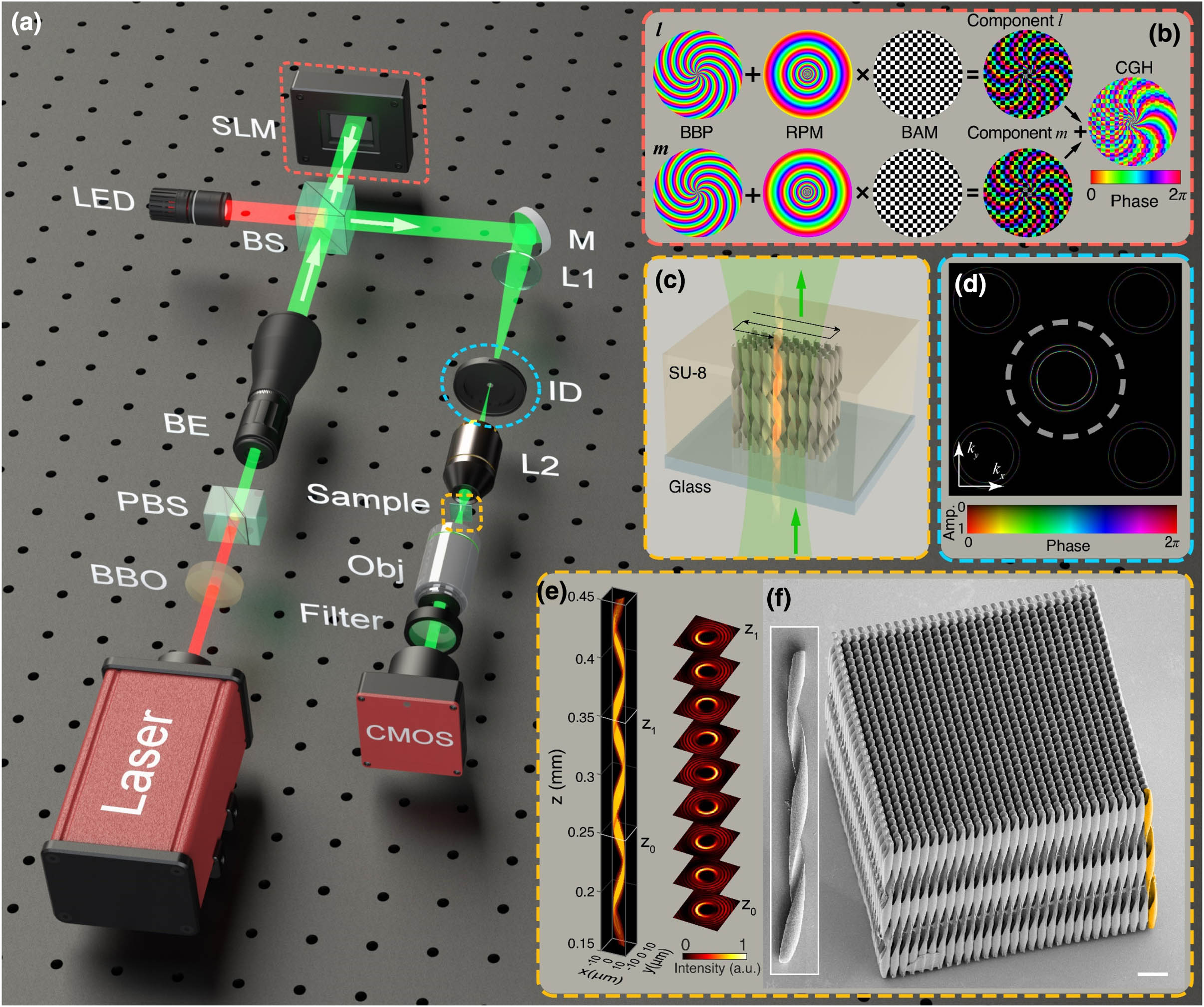
Figure 1.High-throughput microfabrication of helical structures using self-accelerating beams (SABs). (a) Experimental setup: BBO, beta barium borate crystal; PBS, polarizing beam splitter; BE, beam expander; BS, non-polarizing beam splitter; SLM, spatial light modulator; M, mirror; L, lens; ID, iris diaphragm; Obj, objective lens; CMOS, complementary metal–oxide-semiconductor. (b) Calculation of a computer-generated hologram (CGH). Phase order
3. THEORY AND CGH DESIGN
A light field with rotating intensity distribution can be generally described as
Various types of beams have been generated with constant rotation rates. Here we present a general method that produces SABs with axially tunable .
The foundation of our SABs is the superposition of two high-order Bessel beams and the use of radial-to-axial (“”) mapping [39]. The Bessel-beam phase [BBP, Fig. 1(b)] of two Bessel beams with orders and can be expressed in terms of a common radial phase component and their individual azimuthal phase components and [40–43]:
Superposing two Bessel beams having and generates a superposed Bessel beam [44,45] that is still “diffraction free,” and its transversal intensity profile at any has petal-like local maxima that are -fold rotationally symmetric with respect to the optical axis. Inspired by the concept of geometrical mapping [39], we introduce a rotation-tuning function to modulate the phase along the radial direction. This extra phase term, which we call “radial phase modulation” (RPM), is written as
The superposition of these two components gives a transmittance function that is implemented using the SLM. As has both phase and amplitude information, an encoding method is needed for a phase-only SLM. The method we use is based on a pair of complementary “binary amplitude masks” [BAMs, Fig. 1(b)] with checkerboard patterns [46]. After encoding, the phase becomes
The encoded phase is displayed on the SLM as it is illuminated with a Gaussian beam that is expanded to almost fill the aperture of the device. A replica of with demagnification is obtained at the image plane of the system with a low-pass filter applied at the Fourier plane. The resulting transmittance function can be written as .
Using the Fresnel diffraction theory and the stationary phase method [40,47,48], we can derive a closed-form solution for the intensity distribution at point after the image plane (see Appendix A). The solution has a form similar to Eq. (1) except for one term, , where represents the wave vector, , , and represents the beam waist of the Gaussian beam. describes the intensity variation along the axis. The depth of field is finite due to Gaussian illumination, which is similar to the property of a Gaussian–Bessel beam generated by an axicon lens or axicon phase [42,49,50]. To study the rotation of the intensity distribution, this term can be neglected for now. Using Eq. (2), the rotation rate can be determined as
The terms on the right-hand side of Eq. (6) differ by and , where represents the first derivative of with respect to . Equation (6) establishes a “forward” relationship from to . When is a constant, and , and Eq. (6) then reduces to the conclusion in Ref. [33] under the paraxial approximation.
We are more interested in generating an SAB that has a pre-defined , in other words, the “reverse” relationship between and . To find that corresponds to an arbitrary , one can rewrite Eq. (6) as an ordinary linear differential equation, which has a general solution of
4. CHARACTERIZATION OF SELF-ACCELERATING BEAMS IN FREE SPACE
The SABs generated by the proposed method are measured in free space to validate the theory. A CMOS camera with a objective lens shown in Fig. 1(a) is mounted on a motorized stage to image a series of transverse () intensity distributions at positions along the optical axis [Figs. 2(c) and 2(g)].
![]()
Figure 2.Comparison of simulated and measured helical beams with (a)–(d) constant and (e)–(h) decelerated rotation rate. Phase order
The first example is an SAB with a constant rotation rate in air, phase orders , and . The minus sign of means the intensity profile rotates clockwise when viewed opposite from the propagation direction. The experimentally measured transverse intensity profile [Fig. 2(b)] agrees well with the simulation results [Fig. 2(c)]. The SAB has a “C”-shaped transverse profile with a radius around 5 μm. While the beam propagates along the optical axis, the C shape rotates clockwise. Note that the radius can be controlled independently by the choice of phase orders and (see Appendix B), or by changing . The SAB shows a long depth of focus of over 300 μm, which is limited by the SLM aperture and Gaussian beam width. In 3D, the intensity distribution of SABs has a helical shape that resembles a twisted strap. We quantify the rotation by extracting the directional angle from intensity profiles over a fixed axial distance and calculating the rotation rate as . As shown in Fig. 2(d), the measured is close to the designed value. The fluctuation observed in Fig. 2(d) is due to the distortions in the beam profiles, which affects the accuracy of extracted angles.
Another class of SAB has rotation rate that varies with respect to (“chirping”). Figures 2(e)–2(h) show an example with in air, phase order , and . This SAB rotates with a rate that decelerates as it propagates. The white sectors in Fig. 2(f) show that reduced between two 10 μm intervals. We also observe a deviation from the usual C shape in both experiment and simulation at the start of the SABs when exceeds . Here the beam appears as a “double helix” [left side of Fig. 2(e)] and this indicates the existence of an optimal axial range within which good helical shapes can be obtained with this method. In theory, the highest achievable rotation rate is determined by the SLM pixel size and the demagnification ratio of the system. However, there is a limit of the highest rotation rate, beyond which the beam starts to get distorted as shown in Fig. 2(e) (between and 0.15 mm). The SABs reported here could be used in applications beyond fabrication, such as particle manipulation [52] and microfluidic pumping [53,54].
5. PROPAGATION THROUGH INTERFACES
The discussion so far is in free space. In actual fabrication, the SABs pass through multiple interfaces (air–glass, glass–SU-8). Therefore, it is important to understand how SABs propagate through a planar interface of two media with different refractive indices . Because the glass substrate is thin () and its index is close to that of the SU-8, only the air–SU-8 transition is considered. By applying the angular spectrum method [55] and paraxial approximation, the intensity distribution is derived for the SAB after propagating into the photoresist (see Appendix C), from which a few observations can be made. First, the depth of focus elongates by a factor of compared to that in free space. Second, the intensity pattern in the plane does not change after the interface. Finally, the expression of rotation rate can also be obtained by using Eq. (2). We observed that becomes smaller when the beams propagate into a medium with higher . As seen in Appendix C, good agreement is found between the theoretical and simulated profiles (Fig. 9).
6. FABRICATION OF MICRO-HELICES
Equation (7) was used to design CGHs that generate SABs for fabricating helices in SU-8 ( at ). The CGHs have phase order and . Each helix was patterned with static exposure (no scanning) and an exposure time of less than 0.15 ms. The resulting structures were imaged by scanning electron microscopy (SEM). The results are shown in Fig. 3. The length of helical structures is limited by the thickness of the spin-coated SU-8 layer, and variations are due to “edge beads” [56]. The lengths all exceed 150 μm, resulting in aspect ratios over 15. Because of the high aspect ratios, these helices have weak mechanical strength and do not withstand capillary forces or fluid-flow during development. They drift with the solvent and are found lying on the glass substrate after development.
![]()
Figure 3.Comparison between helical beams simulated in SU-8 and fabrication results obtained with five SABs having different types of rotation. The contrast of each SEM image was adjusted individually to improve visibility and aid comparison. Scale bar corresponds to 20 μm.
The left column of Fig. 3 shows the beams used to produce the helical structures. The first two helices [Figs. 3(a) and 3(b)] have constant rotation rate and , and the corresponding pitch is 112 μm and 80 μm, respectively. We can clearly see the difference in pitch from the SEM images. The third helix [Fig. 3(c)] has the opposite rotation rate (handedness) to that in Fig. 3(b). The change of handedness is achieved simply by reversing the sign in Eq. (7). The last two helices [Figs. 3(d) and 3(e)] have axially variable rotation rates (“accelerating”) and (“decelerating”), respectively. Careful examination (see below) shows that the pitches of these helices match the beam shapes. Note that the threshold used in the iso-intensity contours is set arbitrarily for illustration purposes, and it might differ from the actual threshold in fabrication. Therefore, deviation in shape between SABs and fabricated helices is expected. There is slight bending and deformation in the fabricated helices due to the high aspect ratios. With positive-tone photoresists [57], this method could be used to fabricate helical microchannels for microfluidic mixers.
To examine the shape of fabricated helices quantitatively, we use images of single helices and trace their edges. An example is shown in Fig. 4 for a decelerating helix. We have tested various edge-detection algorithms (see Appendix D) and found that their accuracy varies with the specific SEM images given. Therefore, we have decided to extract the edge manually. Since part of the edge is unseen from the SEM image [Fig. 4(a)], a transmission optical microscopic image is used to perform measurements [Fig. 4(b)]. Then the distance to the optical axis is measured at different locations, as shown in Fig. 4(b). The measurement is compared with theoretical prediction calculated by Eq. (6), and a good agreement is found.
![]()
Figure 4.Characterization of a fabricated helix. (a) SEM image of the helix with one edge highlighted. (b) One edge (red solid curve) of the helix is extracted from the optical microscopic image, and the distance
By performing a series of single exposures with lateral translation, helical matrices can be fabricated. Figure 5 shows several matrices, each consisting of helices with a certain pitch and handedness. The fabrication time for each matrix is approximately 15 min, and most of the time is spent on translating the sample. In terms of fabrication volume per unit time, our method is more than 100 times higher than point-by-point scanning for similar structures reported in Ref. [1] (detailed discussion in Appendix E). The fabricaiton time could be further reduced with a galvanometer scanner. The helical structures shown in Fig. 5 can be used as metamaterials at terahertz frequencies [58,59]. Further reduction in pitch can be achieved by tighter focusing (which may require the use of vectorial diffraction theories) and will enable application at the optical frequencies.
![]()
Figure 5.Matrices of various helical structures fabricated by a combination of exposure and linear translation.
7. CONCLUSION
We have demonstrated a method for rapid microfabrication of helical structures with tunable axial shapes by developing a new class of SABs and adapting them to MPP. The SABs are based on the superposition of high-order Bessel modes and form non-diffracting irradiance profiles that rotate along the optical axis. An algorithm was developed to design CGHs that form the SABs. A closed-form expression was derived that can be used to directly synthesize targeted CGH and SAB without resorting to iterative algorithms that yield non-intuitive results. SABs can be generated with independently adjustable transverse width and rotational pitch. Using the concept of mapping, the pitch of the helix can be made to vary with propagation distance . Single and matrices of helices with various pitch and handedness were fabricated in SU-8 with good agreement with the beam shapes. Such helical structures could have applications in metamaterials [1,2,5], microfluidics [9,10], and biomaterials [13]. A reduction in fabrication time exceeding two orders of magnitude over conventional point-by-point scanning MPP is estimated for a fully optimized system. As MPP is maturing towards industrial applications, our method addresses the issue of throughput, and is a step forward for mass microfabrication over large surface areas.
APPENDIX A: GENERATION AND PROPAGATION OF SABS IN FREE SPACE
An SAB with rotating intensity distribution can be generally described as
A special group of SABs with constant has been discussed previously [
The superposition is the desired transmittance function with amplitude and phase information. The task at hand is to find the relationship between and . To this end, we derive the light field intensity resulting from and extract such a relationship. Since contains amplitude information that cannot be generated directly by a phase-only SLM, we use the double-phase-hologram technique reported in Ref. [
In Eqs. (
A CGH described by Eq. (
![]()
Figure 6.Propagation model used in the derivation.
In Eq. (
Equations (
Using the Fresnel diffraction integral in cylindrical coordinates, we can write the complex field at point after the image plane as
Substituting Eqs. (
Using an integral representation of Bessel functions [
Because the phase term in Eq. (
Now we can superpose Eq. (
It is obvious that . Note that the term in Eq. (
Equation (
Substituting Eq. (
When the function is a constant, the rotation rate , which is also a constant. For more general cases, the axially dependent rotation rate can be determined as
Treating as unknown, we can rewrite Eq. (
Equation (
APPENDIX B: TUNING TRANSVERSE BEAM PROFILE
Notice that Eqs. (
![]()
Figure 7.Simulation results of two beams with (a) large and (b) small helical diameters generated by changing the phase order
APPENDIX C: PROPAGATION THROUGH AN INTERFACE
Now we consider the situation in which the beam propagates from air through the air–photoresist interface. Here we ignore the glass substrate because it is thin () and has a refractive index similar to that of the photoresist SU-8 (the difference is 0.1 at 515 nm). We assume that (1) the image plane of the system discussed in the previous section is located in air and at a distance before the planar air–photoresist interface, and (2) the photoresist is homogeneous with a refractive index (Fig.
![]()
Figure 8.Schematic for the propagation of helical beams into photoresist. L2 is the second lens of the
![]()
Figure 9.(a) Theory and (b) simulation of intensity distribution on the
APPENDIX D: CHARACTERIZATION OF HELICAL STRUCTURES
To examine the shape of the fabricated helices quantitatively, we use images of single helices and trace their edges. An example is shown in Figs.
![]()
Figure 10.Characterization of a fabricated helix from an SEM image. (a) Original image. (b) The edges are detected from the image by edge-detection algorithms. (c) Noise is suppressed and only one edge is displayed. (d) Locations along the edge are plotted.
![]()
Figure 11.Characterization of a fabricated helix from a transmissive optical microscopic image. Red curve overlayed on the image is used to illustrate the edge that is extracted.
APPENDIX E: ESTIMATION OF FABRICATION TIME
Here we compare the time required to fabricate one helical structure using the high-throughput method reported in this work to that required for MPP by conventional point-by-point scanning. The scanning rate is the major bottleneck in the fabrication time for MPL, and it can be improved by moving the beam using galvo-mirrors, instead of translating the sample with a piezo-stage [
References
[1] M. Thiel, M. Decker, M. Deubel, M. Wegener, S. Linden, G. von Freymann. Polarization stop bands in chiral polymeric three-dimensional photonic crystals. Adv. Mater., 19, 207-210(2007).
[2] J. K. Gansel, M. Thiel, M. S. Rill, M. Decker, K. Bade, V. Saile, G. von Freymann, S. Linden, M. Wegener. Gold helix photonic metamaterial as broadband circular polarizer. Science, 325, 1513-1515(2009).
[3] J. B. Pendry. A chiral route to negative refraction. Science, 306, 1353-1355(2004).
[4] E. Plum, J. Zhou, J. Dong, V. A. Fedotov, T. Koschny, C. M. Soukoulis, N. I. Zheludev. Metamaterial with negative index due to chirality. Phys. Rev. B, 79, 035407(2009).
[5] J. K. Gansel, M. Latzel, A. Frölich, J. Kaschke, M. Thiel, M. Wegener. Tapered gold-helix metamaterials as improved circular polarizers. Appl. Phys. Lett., 100, 101109(2012).
[6] J. Kaschke, L. Blume, L. Wu, M. Thiel, K. Bade, Z. Yang, M. Wegener. A helical metamaterial for broadband circular polarization conversion. Adv. Opt. Mater., 3, 1411-1417(2015).
[7] C. Wu, H. Li, X. Yu, F. Li, H. Chen, C. T. Chan. Metallic helix array as a broadband wave plate. Phys. Rev. Lett., 107, 177401(2011).
[8] Z. Lu, M. Zhao, Z. Yang, L. Wu, P. Zhang, Y. Zheng, J. Duan. Broadband polarization-insensitive absorbers in 0.3–25 μm using helical metamaterials. J. Opt. Soc. Am. B, 30, 1368-1372(2013).
[9] M. K. S. Verma, S. R. Ganneboyina, , A. Ghatak. Three-dimensional multihelical microfluidic mixers for rapid mixing of liquids. Langmuir, 24, 2248-2251(2008).
[10] C. Shan, F. Chen, Q. Yang, Z. Jiang, X. Hou. 3D multi-microchannel helical mixer fabricated by femtosecond laser inside fused silica. Micromachines, 9, 29(2018).
[11] M. I. Hussain, G. H. Lee, B. Engineering. Numerical thermal analysis of helical-shaped heat exchanger to improve thermal stratification inside solar. International Conference on Agricultural and Environmental Engineering, 6-10(2014).
[12] E. S. Shukri. Numerical comparison of temperature distribution in an annular diffuser fitted with helical screw-tape hub and pimpled hub. Energy Proc., 141, 625-629(2017).
[13] A. V. Do, B. Khorsand, S. M. Geary, A. K. Salem. 3D printing of scaffolds for tissue regeneration applications. Adv. Healthcare Mater., 4, 1742-1762(2015).
[14] M. Thiel, M. S. Rill, G. von Freymann, M. Wegener. Three-dimensional bi-chiral photonic crystals. Adv. Mater., 21, 4680-4682(2009).
[15] J. Kaschke, M. Wegener. Gold triple-helix mid-infrared metamaterial by STED-inspired laser lithography. Opt. Lett., 40, 3986-3989(2015).
[16] Y. Liu, J. Campbell, O. Stein, L. Jiang, J. Hund, Y. Lu. Deformation behavior of foam laser targets fabricated by two-photon polymerization. Nanomaterials, 8, 498(2018).
[17] G. Kumi, C. O. Yanez, K. D. Belfield, J. T. Fourkas. High-speed multiphoton absorption polymerization: fabrication of microfluidic channels with arbitrary cross-sections and high aspect ratios. Lab Chip, 10, 1057-1060(2010).
[18] S. Kawata, H. B. Sun, T. Tanaka, K. Takada. Finer features for functional microdevices. Nature, 412, 697-698(2001).
[19] L. Yang, S. Ji, K. Xie, W. Du, B. Liu, Y. Hu, J. Li, G. Zhao, D. Wu, W. Huang, S. Liu, H. Jiang, J. Chu. High efficiency fabrication of complex microtube arrays by scanning focused femtosecond laser Bessel beam for trapping/releasing biological cells. Opt. Express, 25, 8144-8157(2017).
[20] S. Ji, L. Yang, C. Zhang, Z. Cai, Y. Hu, J. Li, D. Wu, J. Chu. High-aspect-ratio microtubes with variable diameter and uniform wall thickness by compressing Bessel hologram phase depth. Opt. Lett., 43, 3514-3517(2018).
[21] S. Ji, L. Yang, Y. Hu, J. Ni, W. Du, J. Li, G. Zhao, D. Wu, J. Chu. Dimension-controllable microtube arrays by dynamic holographic processing as 3D yeast culture scaffolds for asymmetrical growth regulation. Small, 13, 1701190(2017).
[22] L. Yang, D. Qian, C. Xin, Z. Hu, S. Ji, D. Wu, Y. Hu, J. Li, W. Huang, J. Chu. Two-photon polymerization of microstructures by a non-diffraction multifoci pattern generated from a superposed Bessel beam. Opt. Lett., 42, 743-746(2017).
[23] L. Yang, D. Qian, C. Xin, Z. Hu, S. Ji, D. Wu, Y. Hu, J. Li, W. Huang, J. Chu. Direct laser writing of complex microtubes using femtosecond vortex beams. Appl. Phys. Lett., 110, 221103(2017).
[24] H. Cheng, C. Xia, M. Zhang, S. M. Kuebler, X. Yu. Fabrication of high-aspect-ratio structures using Bessel-beam-activated photopolymerization. Appl. Opt., 58, D91-D97(2019).
[25] J. Jezek, T. Cizmár, V. Nedela, P. Zemánek. Formation of long and thin polymer fiber using nondiffracting beam. Opt. Express, 14, 8506-8515(2006).
[26] D. Pan, B. Xu, S. Liu, J. Li, Y. Hu, D. Wu, J. Chu. Amplitude-phase optimized long depth of focus femtosecond axilens beam for single-exposure fabrication of high-aspect-ratio microstructures. Opt. Lett., 45, 2584-2587(2020).
[27] S.-J. Zhang, Y. Li, Z.-P. Liu, J.-L. Ren, Y.-F. Xiao, H. Yang, Q. Gong. Two-photon polymerization of a three dimensional structure using beams with orbital angular momentum. Appl. Phys. Lett., 105, 061101(2014).
[28] J. Ni, C. Wang, C. Zhang, Y. Hu, L. Yang, Z. Lao, B. Xu, J. Li, D. Wu, J. Chu. Three-dimensional chiral microstructures fabricated by structured optical vortices in isotropic material. Light Sci. Appl., 6, e17011(2017).
[29] Y. Li, L. Liu, D. Yang, Q. Zhang, H. Yang, Q. Gong. Femtosecond laser nano/microfabrication via three-dimensional focal field engineering. Proc. SPIE, 10092, 100920B(2017).
[30] J. Kaschke, J. K. Gansel, M. Wegener. On metamaterial circular polarizers based on metal
[31] J. K. Gansel, M. Wegener, S. Burger, S. Linden. Gold helix photonic metamaterials: a numerical parameter study. Opt. Express, 18, 1059-1069(2010).
[32] C. Vetter, T. Eichelkraut, M. Ornigotti, A. Szameit. Optimization and control of two-component radially self-accelerating beams. Appl. Phys. Lett., 107, 211104(2015).
[33] C. Vetter, T. Eichelkraut, M. Ornigotti, A. Szameit. Generalized radially self-accelerating helicon beams. Phys. Rev. Lett., 113, 183901(2014).
[34] R. Rop, A. Dudley, C. López-Mariscal, A. Forbes. Measuring the rotation rates of superpositions of higher-order Bessel beams. J. Mod. Opt., 59, 259-267(2012).
[35] R. Vasilyeu, A. Dudley, N. Khilo, A. Forbes. Generating superpositions of higher-order Bessel beams. Opt. Express, 17, 23389-23395(2009).
[36] C. Schulze, F. S. Roux, A. Dudley, R. Rop, M. Duparré, A. Forbes. Accelerated rotation with orbital angular momentum modes. Phys. Rev. A, 91, 043821(2015).
[37] C. Vetter, A. Dudley, A. Szameit, A. Forbes. Real and virtual propagation dynamics of angular accelerating white light beams. Opt. Express, 25, 20530-20540(2017).
[38] J. Webster, C. Rosales-Guzmán, A. Forbes. Radially dependent angular acceleration of twisted light. Opt. Lett., 42, 675-678(2017).
[39] H. Cheng, C. Xia, S. M. Kuebler, X. Yu. Aberration correction for SLM-generated Bessel beams propagating through tilted interfaces. Opt. Commun., 475, 126213(2020).
[40] A. Vasara, J. Turunen, A. T. Friberg. Realization of general nondiffracting beams with computer-generated holograms. J. Opt. Soc. Am. A, 6, 1748-1754(1989).
[41] N. Chattrapiban, E. A. Rogers, D. Cofield, W. T. Hill, R. Roy. Generation of nondiffracting Bessel beams by use of a spatial light modulator. Opt. Lett., 28, 2183-2185(2003).
[42] C. Paterson, R. Smith. Higher-order Bessel waves produced by axicon-type computer-generated holograms. Opt. Commun., 124, 121-130(1996).
[43] X. Yu, A. Todi, H. Tang. Bessel beam generation using a segmented deformable mirror. Appl. Opt., 57, 4677-4682(2018).
[44] H. Cheng, C. Xia, S. M. Kuebler, P. Golvari, M. Sun, M. Zhang, X. Yu. Generation of Bessel-beam arrays for parallel fabrication in two-photon polymerization. J. Laser Appl., 33, 012040(2021).
[45] X. Yu, C. A. Trallero-Herrero, S. Lei. Materials processing with superposed Bessel beams. Appl. Surf. Sci., 360, 833-839(2016).
[46] O. Mendoza-Yero, G. Mínguez-Vega, J. Lancis. Encoding complex fields by using a phase-only optical element. Opt. Lett., 39, 1740-1743(2014).
[47] L. B. Felsen, N. Marcuvitz. Radiation and Scattering of Waves(1994).
[48] A. V. Osipov, S. A. Tretyakov. Modern Electromagnetic Scattering Theory with Applications(2017).
[49] J. Arlt, K. Dholakia. Generation of high-order Bessel beams by use of an axicon. Opt. Commun., 177, 297-301(2000).
[50] V. Jarutis, R. Paškauskas, A. Stabinis. Focusing of Laguerre–Gaussian beams by axicon. Opt. Commun., 184, 105-112(2000).
[51] G. Whyte, J. Courtial. Experimental demonstration of holographic three-dimensional light shaping using a Gerchberg–Saxton algorithm. New J. Phys., 7, 117(2005).
[52] B. Hadad, S. Froim, H. Nagar, T. Admon, Y. Eliezer, Y. Roichman, A. Bahabad. Particle trapping and conveying using an optical Archimedes’ screw. Optica, 5, 551-556(2018).
[53] A. Terray. Microfluidic control using colloidal devices. Science, 296, 1841-1844(2002).
[54] P. Galajda, P. Ormos. Rotors produced and driven in laser tweezers with reversed direction of rotation. Appl. Phys. Lett., 80, 4653-4655(2002).
[55] J. W. Goodman. Introduction to Fourier Optics(2005).
[56] H. Lee, K. Lee, B. Ahn, J. Xu, L. Xu, K. W. Oh. A new fabrication process for uniform SU-8 thick photoresist structures by simultaneously removing edge bead and air bubbles. J. Micromech. Microeng., 21, 125006(2011).
[57] W. Zhou. An efficient two-photon-generated photoacid applied to positive-tone 3D microfabrication. Science, 296, 1106-1109(2002).
[58] S. Li, Z. Yang, J. Wang, M. Zhao. Broadband terahertz circular polarizers with single- and double-helical array metamaterials. J. Opt. Soc. Am. A, 28, 19-23(2011).
[59] Y. Yu, Z. Yang, M. Zhao, P. Lu. Broadband optical circular polarizers in the terahertz region using helical metamaterials. J. Opt., 13, 055104(2011).
[61] C. N. LaFratta, L. Li. Making two-photon polymerization faster. Three-Dimensional Microfabrication Using Two-Photon Polymerization, 385-408(2020).
[62] M. A. Skylar-Scott, M. C. Liu, Y. Wu, A. Dixit, M. F. Yanik. Guided homing of cells in multi-photon microfabricated bioscaffolds. Adv. Healthc. Mater., 5, 1233-1243(2016).
[63] B. W. Pearre, C. Michas, J. M. Tsang, T. J. Gardner, T. M. Otchy. Fast micron-scale 3D printing with a resonant-scanning two-photon microscope. Addit. Manuf., 30, 100887(2019).
[64] A. Ovsianikov, A. Deiwick, S. Van Vlierberghe, P. Dubruel, L. Möller, G. Drager, B. Chichkov. Laser fabrication of three-dimensional CAD scaffolds from photosensitive gelatin for applications in tissue engineering. Biomacromolecules, 12, 851-858(2011).

Set citation alerts for the article
Please enter your email address
© Copyright 2018-2021 | Chinese Laser Press. All Rights Reserved 沪ICP备15018463号-20