• Chinese Optics Letters
  • Vol. 20, Issue 2, 023801 (2022)
Chenchu Zhang1、*, Hanchang Ye1, Rui Cao2, Shengyun Ji3, Heng Zhang1, Linhan Zhao1, Sizhu Wu1、**, and Hua Zhai1
Author Affiliations
  • 1Anhui Province Key Laboratory of Aerospace Structural Parts Forming Technology and Equipment, Institute of Industry and Equipment Technology, Hefei University of Technology, Hefei 230009, China
  • 2Caltech Optical Imaging Laboratory, Andrew and Peggy Cherng Department of Medical Engineering, California Institute of Technology, Pasadena, CA 91125, USA
  • 3Hefei National Laboratory for Physical Sciences at the Microscale and CAS Key Laboratory of Mechanical Behavior and Design of Materials, Department of Precision Machinery and Precision Instrumentation, University of Science and Technology of China, Hefei 230026, China
  • show less
    DOI: 10.3788/COL202220.023801 Cite this Article Set citation alerts
    Chenchu Zhang, Hanchang Ye, Rui Cao, Shengyun Ji, Heng Zhang, Linhan Zhao, Sizhu Wu, Hua Zhai. Rapid fabrication of microrings with complex cross section using annular vortex beams[J]. Chinese Optics Letters, 2022, 20(2): 023801 Copy Citation Text show less
    (a) Generation schematic of AVB. (b) Simulated foci of vortex beam, AB, and AVB. (c) Diameter of ring-shaped focus versus the topological charge of vortex beams, and widths of zeroth-order AB and AVB.
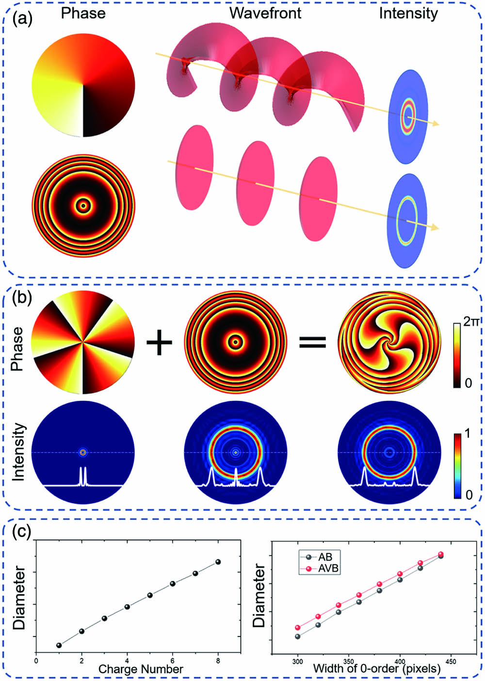
    Fig. 1. (a) Generation schematic of AVB. (b) Simulated foci of vortex beam, AB, and AVB. (c) Diameter of ring-shaped focus versus the topological charge of vortex beams, and widths of zeroth-order AB and AVB.
    (a) Experimental setup of AVB-based fabrication system. The right is the simulated intensity distribution along the propagation direction. (b) Simulated and (c) experimentally tested intensity distributions in different planes corresponding to dashed lines shown in (a).
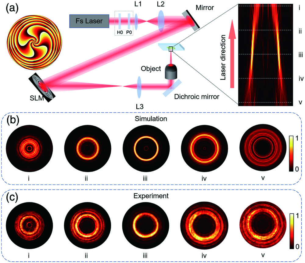
    Fig. 2. (a) Experimental setup of AVB-based fabrication system. The right is the simulated intensity distribution along the propagation direction. (b) Simulated and (c) experimentally tested intensity distributions in different planes corresponding to dashed lines shown in (a).
    (a) Phase of AVBs with different zero-order width. (b) Simulation intensity distribution of ring-shaped focus with different diameters. (c) Experimental intensity distribution of ring-shaped focus with different diameters. (d) SEM images of microtubes fabricated by single exposure of AVBs with different diameters. (e) Comparison of processing time between the single-exposure method and single-point scanning method. (f) Comparison of diameters of simulated ring-shaped foci, experimentally tested ring-shaped foci, and fabricated microstructures. Scale bars are 20 µm.
    Fig. 3. (a) Phase of AVBs with different zero-order width. (b) Simulation intensity distribution of ring-shaped focus with different diameters. (c) Experimental intensity distribution of ring-shaped focus with different diameters. (d) SEM images of microtubes fabricated by single exposure of AVBs with different diameters. (e) Comparison of processing time between the single-exposure method and single-point scanning method. (f) Comparison of diameters of simulated ring-shaped foci, experimentally tested ring-shaped foci, and fabricated microstructures. Scale bars are 20 µm.
    (a) Generation principle of AVB with fractional topological charge. (b) Simulated gap-ring focus distribution. (c) Experimentally tested gap-ring focus distribution. The topological charges vary from 5.1 to 5.5 in (b) and (c). (d)–(h) SEM images of micro gap rings fabricated by single exposure of gap-ring focus. The top right corners are the corresponding foci. Scale bar is 10 µm. (i) Relationship between the gap size of fabricated microrings and the topological charges.
    Fig. 4. (a) Generation principle of AVB with fractional topological charge. (b) Simulated gap-ring focus distribution. (c) Experimentally tested gap-ring focus distribution. The topological charges vary from 5.1 to 5.5 in (b) and (c). (d)–(h) SEM images of micro gap rings fabricated by single exposure of gap-ring focus. The top right corners are the corresponding foci. Scale bar is 10 µm. (i) Relationship between the gap size of fabricated microrings and the topological charges.
    Chenchu Zhang, Hanchang Ye, Rui Cao, Shengyun Ji, Heng Zhang, Linhan Zhao, Sizhu Wu, Hua Zhai. Rapid fabrication of microrings with complex cross section using annular vortex beams[J]. Chinese Optics Letters, 2022, 20(2): 023801
    Download Citation