
Bin Shen, Huai Xiong, Xu Zhang, Zhiya Chen, Xiangyang Pang, Yajing Guo, Chengjie Liang, Haiyuan Li. Post-treatment of 351 nm SiO2 antireflective coatings for high power laser systems prepared by the sol-gel method[J]. Chinese Optics Letters, 2022, 20(1): 011601
- Chinese Optics Letters
- Vol. 20, Issue 1, 011601 (2022)
Abstract
Keywords
1. Introduction
The sol-gel method, which was first, to the best of our knowledge, described by Ebelmen in 1846, has since been widely used to prepare different kinds of materials[
After studying the post-treatment processes for AR coatings used in different HPLSs, including NIF, LMJ, and SG II[
2. Experiments
The sol was prepared using purified tetraethoxysilane (TEOS), ammonia (), ethanol (EtOH), and polyethylene glycol (PEG200). The molar ratio of the chemical reagents in the solution was , and a certain amount of PEG200 was added. After stirring the solution in ice water for a specific duration, the sealed solution was aged for some days in an oven set to 50°C. The solution was then refluxed to remove excess until the pH of the sol was seven. Finally, the sol used for the AR coating via dip coating was obtained by diluting the initial sol with a certain amount of EtOH.
Sign up for Chinese Optics Letters TOC. Get the latest issue of Chinese Optics Letters delivered right to you!Sign up now
The JGS1 (far ultraviolet silica fused glass, transparent in the range of ultraviolet and visible spectra) substrates with a diameter and thickness of 32 and 7 mm, respectively, were completely immersed in the sol at a speed of 5–10 cm/min. The substrates were then pulled out at the same speed using a custom-made dip coating machine. The actual coating process usually needs to test the peak wavelength () of coating transmittance and adjust the dip coating speed. After the JGS1 substrates with AR coatings were placed in a drying cabinet for more than 2 h, they were heat-treated in an oven at 180°C for 24 h to obtain a heat-treated AR coating (JGS1 with AR) whose optical thickness () is about 88 nm.
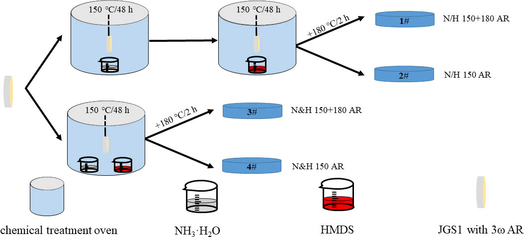
All of the JGS1 samples with AR coatings were post-treated via different processes in a chemical atmosphere, as shown in Fig. 1. Two beakers containing approximately 30 mL each of and HMDS were heated in an oven at 150°C for 48 h to constitute two different post-treatment processes [two steps (1, 2) and one step (3, 4)]. Finally, JGS1 substrates 1 and 3 were heat-treated for another 2 h at 180°C.
![]()
Figure 1.Schematic diagram showing post-treatment processes of 3ω AR.
3. Results and Discussion
Typically, the refractive index of silica AR coatings is approximately 1.20, and coating elements with excellent AR performance for can be obtained and applied to the final output main optical path of HPLSs by matching the refractive index of the AR coating with that of the element. However, due to the porous nature of the sol-gel silica coating, the coating elements, when used in laser devices for a long time, are mainly affected by the experimental environment, such as water vapor in air and contaminants in the devices. Typically, the stability of the silica coatings will decrease under such environmental conditions over time. The stability performance of silica coatings can be determined by their optical properties, contact angles, and surface defects.
Samples 1–4 were placed in the high temperature, high humidity Espec LH-213 oven for 24 h, where the temperature and relative humidity of the oven were set to 85°C and 85% (85°C/85 RH), respectively. The changes in the performance of the coating were determined under extreme temperature and humidity conditions to simulate experimental conditions. The transmittances of samples 1–4 under different experimental conditions were tested using a Lambda900 spectrophotometer (PerkinElmer, USA). The optical performances of samples 1–4 at different experimental stages are illustrated in Fig. 2; note that the testing range for spectrophotometry was 200–800 nm. The peak transmittance () and wavelength () of the corresponding samples are shown in Table 1. Figure 2 indicates that all samples undergo a slight red shift at the peak transmittance after post-treatment because the hydrophobic trimethyl groups are attached to the surface of the silica coating after post-treatment. Samples 1 and 3 exhibit similar peak transmittances before and after post-treatment, while samples 2 and 4 exhibit peak transmittances reduced by 0.15% and 0.21%, respectively, after post-treatment; and the peak wavelength of samples 2 and 4 red shifted about 20 nm. In the post-treatment process, the gasification of and HMDS created a sealed oven to form a chemical atmosphere. The HMDS gas perhaps gradually liquefied to form microbeads that blocked the pores of the silica coating when the oven temperature was decreased; this increased the refractive index of the silica coating and decreased the transmittance of the element. The microbeads in the porous silica coating were discharged by another round of heat treatment in an oven at 180°C for 2 h. At the same time, the peak wavelengths of the samples did not exhibit a noticeable shift after 85°C/85 RH environment, while the peak transmittance of the samples decreased in general and the peak transmittance of sample 1 after 85°C/85 RH environment was the highest (99.28%) among all the samples. This indicates that the water molecules infiltrated the pores of the silica coatings, leading to a decrease in the peak transmittance. The lower decrease in the peak transmittance of sample 1 may be because the surface of the silica coating subjected to the two-step post-treatment reacted more efficiently with and HMDS than that of the coating subjected to the one-step post-treatment and because the surfaces of the silica coatings were covered with hydrophobic groups.
| Sample | Effect of Heat Treatment | Effect of Heat Treatment and Post-Treatment | Effect of 85°C/85 RH | |||
|---|---|---|---|---|---|---|
| 1 | 368 | 99.58 | 374 | 99.55 | 376 | 99.28 |
| 2 | 355 | 99.65 | 373 | 99.50 | 372 | 99.03 |
| 3 | 366 | 99.65 | 369 | 99.67 | 388 | 98.42 |
| 4 | 354 | 99.67 | 374 | 99.46 | 372 | 99.25 |
Table 1. Peak Transmittance and Wavelength of 3
![]()
Figure 2.Optical performance of 3ω AR coatings at different experimental stages: (a) sample 1, (b) sample 2, (c) sample 3, (d) sample 4.
The water contact angles of the silica coatings after post-treatment and 30 days after the end of the high temperature, high humidity experiment were measured using the optical contact angle (OCA) 40 system (Dataphysics Instruments, Germany); the results are shown in Fig. 3. For the test, 3 µL deionized water droplets were used, and the coating was in contact with the water droplet for 10 s before being sampled. Hydrophobic groups were formed on the surface of the silica coatings, resulting in good hydrophobic properties after post-treatment. All four samples exhibited contact angles greater than 125° between the silica coating and water droplet; the contact angle of sample 1 was close to 130°, indicating excellent hydrophobic properties. The water contact angles of all samples were maintained at approximately 120° after testing under extreme conditions, which showed that different post-treatment processes can induce better hydrophobicity on the surface of silica coatings.
![]()
Figure 3.Water contact angles of the 3ω AR coatings.
The basis of the coating stability was the stability of the coating transmittance and hydrophobicity; however, changes in the surface defects of silica coatings will eventually affect the LIDT of the silica coating[
![]()
Figure 4.Defect positions of all samples. (a)–(d) samples 1–4 before 85°C/85 RH treatment, (e)–(h) samples 1–4 after 85°C/85 RH treatment.
The particulate contaminants from motors, lubricants, and organic plasticizers are volatilized inside the vacuum components during experimentation with HPLSs, which will also affect the properties of the sol-gel coatings[
![]()
Figure 5.Transmittance spectra before and after contamination: (a) sample 1, (b) sample 2, (c) sample 3, (d) sample 4.
![]()
Figure 6.Transmission loss of samples at 351 nm.
The defects in the optical coatings were the main source of damage under long-pulse laser irradiation[
![]()
Figure 7.LIDT (355 nm, 6.8 ns) results of the samples.
4. Conclusion
In conclusion, post-treatment is an important process in preparing sol-gel coatings for optical elements. This study aimed to optimize the post-treatment process for sol-gel coatings using experiments that can be applied to HPLSs. The comprehensive performance of AR coatings with the post-treatment process of N/H 150 + 180 AR was the most efficient in terms of the parameters tested (i.e., transmittance, defect density, water contact angle, and LIDT).
References
[1] E. Ebelmen. Researches sur les combinaisons des acides borique et silicique avecles ethers. Ann. Chim. Phys., 16, 129(1846).
[2] J. H. Campbell, R. Hawley-Fedder, C. J. Stolz, J. A. Menapace, M. R. Borden, P. Whitman, J. Yu, M. Runkel, M. Riley, M. Feit, R. Hackel. NIF optical materials and fabrication technologies: an overview. Proc. SPIE, 5341, 84(2004).
[3] P. Belleville, P. Prene, C. Bonnin, L. Beaurain, Y. Montouillout. How smooth chemistry allows high power laser optical coating preparation. Proc. SPIE, 5250, 196(2004).
[4] R. J. Liu, R. Y. Zhan, Y. X. Tang, J. Q. Zhu. A moisture-resistant antireflective coating by sol-gel process for neodymium-doped phosphate laser glass. Chin. Opt. Lett., 4, 119(2006).
[5] Y. Wei, H. B. Lü, X. D. Jiang, C. Tang, H. Ren, K. Li. Fabrication of broadband antireflective films by sol-gel spin-coating process for high power lasers. High Power Laser Particle Beams, 15, 647(2003).
[6] J. Q. Zhu. Review of special issue on high power facility and technical development at the NLHPLP. High Power Laser Sci. Eng., 7, e12(2019).
[7] F. Suzuki-Vidal, T. Clayson, C. Stehle, U. Chaulagain, J. W. D. Halliday, M. Y. Sun, L. Ren, N. Kang, H. Y. Liu, B. Q. Zhu, J. Q. Zhu, C. D. Rossi, T. Mihailescu, P. Velarde, M. Cotelo, J. M. Foster, C. N. Danson, C. Spindloe, J. P. Chittenden, C. Kuranz. First radiative shock experiments on the SG-II laser. High Power Laser Sci. Eng., 9, e27(2021).
[8] H. Xiong, Y. X. Tang, L. L. Hu, H. Y. Li. An ORMOSIL porous double-layer broadband antireflective coating. Chin. Opt. Lett., 17, 112201(2019).
[9] M. G. Blanchin, B. Canut, Y. Lambert, V. S. Teodorescu, A. Barau, M. Zaharescu. Structure and dielectric properties of HfO2 films prepared by a sol–gel route. J. Sol-Gel Sci. Technol., 47, 165(2008).
[10] P. Belleville, P. Prené, B. Lambert. UV-cured sot-gel broadband antireflective and scratch-resistant coating for CRT. Proc. SPIE, 3943, 67(2000).
[11] Y. J. Guo, X. T. Zu, X. D. Jiang, X. D. Yuan, W. G. Zheng, S. Z. Xu, B. Y. Wang. Laser-induced damage mechanism of the sol–gel single-layer SiO2 acid and base thin films. Nucl. Instrum. Methods Phys. Res. B, 266, 3190(2008).
[12] M. L. Spaeth, K. R. Manes, D. H. Kalantar, P. E. Miller, J. E. Heebner, E. S. Bliss, D. R. Speck, T. G. Parham, P. K. Whitman, P. J. Wegner, P. A. Baisden, J. A. Menapace, M. W. Bowers, S. J. Cohen, T. I. Suratwala, J. M. Di Nicola, M. A. Newton, J. J. Adams, J. B. Trenholme, R. G. Finucane, R. E. Bonanno, D. C. Rardin, P. A. Arnold, S. N. Dixit, G. V. Erbert, A. C. Erlandson, J. E. Fair, E. Feigenbaum, W. H. Gourdin, R. A. Hawley, J. Honig, R. K. House, K. S. Jancaitis, K. N. LaFortune, D. W. Larson, B. J. Le Galloudec, J. D. Lindl, B. J. MacGowan, C. D. Marshall, K. P. McCandless, R. W. McCracken, R. C. Montesanti, E. I. Moses, M. C. Nostrand, J. A. Pryatel, V. S. Roberts, S. B. Rodriguez, A. W. Rowe, R. A. Sacks, J. T. Salmon, M. J. Shaw, S. Sommer, C. J. Stolz, G. L. Tietbohl, C. C. Widmayer, R. Zacharias. Description of the NIF laser. Fusion Sci. Technol., 69, 25(2016).
[13] S. D. Wang, Y. Y. Shu. Superhydrophobic antireflective coating with high transmittance. J. Coat. Technol. Res., 10, 527(2013).
[14] Q. H. Zhang, W. Yang, H. J. Ma, P. Ma, Q. Xu. Modification of porous silica antireflective coatings with fluorine-containing organosilicon. Acta Opt. Sin., 29, 1719(2009).
[15] M. Y. Wei, X. M. Wang, S. G. Qing, Z. K. Luo, H. X. Zheng, S. Q. Liu. Preparation of KH560/KH570 modified SiO2 antireflective coating. Mater. Rep. B, 26, 7(2012).
[16] M. V. Monticelli, M. C. Nostrand, N. Mehta, L. Kegelmeyer, M. A. Johnson, J. Fair, C. Widmayer. The HMDS coating flaw removal tool. Proc. SPIE, 7132, 71320V(2008).
[17] D. S. Hobbs, B. D. Macleod, E. Sabatino, J. A. Britten, C. J. Stolz. Contamination resistant antireflection nano-textures in fused silica for laser optics. Proc. SPIE, 8885, 88850J(2013).
[18] P. F. Belleville, H. G. Floch. Ammonia hardening of porous silica antireflective coatings. Proc. SPIE, 2288, 25(1994).
[19] H. Y. Li, Y. X. Tang. Study on stability of porous silica antireflective coatings prepared by sol-gel processing. Chin. J. Lasers, 32, 839(2005).
[20] C. L. Zhang, X. B. Li, H. B. Lü, X. D. Yuan, Z. G. Wang, X. T. Zu. Influence of impurities on laser-induced damage of sol-gel SiO2 films. High Power Laser Particle Beams, 23, 1267(2011).
[21] I. M. Thomas, A. K. Burnham, J. R. Ertel, S. C. Frieders. Method for reducing the effect of environmental contamination of sol gel optical coatings. Proc. SPIE, 3492, 220(1999).
[22] X. Y. Pang, M. Y. Sun, Q. T. Fan, H. Xiong, C. Y. Wang, Z. G. Liu. Online detection of airborne molecular contamination and its influence on the sol-gel coating. Proc. SPIE, 10748, 107480Z(2018).
[23] C. Shan, Y. A. Zhao, Y. Q. Gao, X. H. Zhao, G. H. Hu, W. X. Ma, J. D. Shao. Laser-induced defects in optical multilayer coatings by the spatial resolved method. Chin. Opt. Lett., 17, 031403(2019).
[24] T. Y. Pu, W. W. Liu, Y. L. Wang, X. M. Pan, L. Q. Chen, X. F. Liu. A novel laser shock post-processing technique on the laser-induced damage resistance of 1ω HfO2/SiO2 multilayer coatings. High Power Laser Sci. Eng., 9, e19(2021).

Set citation alerts for the article
Please enter your email address
© Copyright 2018-2021 | Chinese Laser Press. All Rights Reserved 沪ICP备15018463号-20