
Guodong Wang, Qingqing Meng, Hengli Han, Xuan Li, Yixiao Zhou, Zihang Zhu, Congrui Gao, He Li, Shanghong Zhao. Photonic generation of switchable multi-format linearly chirped signals[J]. Chinese Optics Letters, 2022, 20(6): 063901
- Chinese Optics Letters
- Vol. 20, Issue 6, 063901 (2022)
Abstract
1. Introduction
A linearly chirped signal, a well-known type of pulse compression signal, as well as a spread spectrum signal, has been widely used in radar and wireless communication systems[
The above studies have their own strengths and weaknesses but mainly focus on signal generation. In some scenarios, the generation of linearly chirped signals can be combined with digital modulation to enhance radar performance or perform wireless communication with low probability of intercept (LPI). In Refs. [17–19], a linearly chirped signal with amplitude or phase modulation is generated in a frequency-to-time mapping system. The obtained signal is demonstrated to be used for synthesis to realize arbitrary long time-bandwidth product (TBWP), or for error-free wireless communication with multipath pre-compensation. However, the multiple elements and spatially separated structure make the systems complex and unstable. Recently, we have proposed a signal generator for radar application and wireless communication[
In this Letter, we propose a photonic scheme to generate switchable multi-format linearly chirped signals with a simple structure, in which only a dual-drive Mach–Zehnder modulator (DDMZM) is employed. The input signals contain a coding sequence and a linearly chirped waveform. By adjusting the amplitudes of the coding sequence, a linearly chirped signal with switchable format, including the frequency shift keying (FSK), PSK, dual-band PSK, and FSK/PSK modulation formats, can be generated.
Sign up for Chinese Optics Letters TOC. Get the latest issue of Chinese Optics Letters delivered right to you!Sign up now
2. Principle
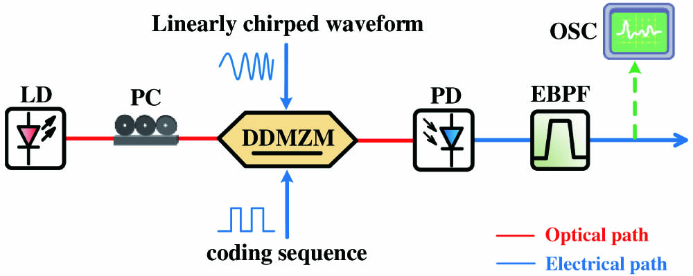
Figure 1 shows the schematic diagram of the switchable multi-format linearly chirped signal generator. An optical carrier from a laser diode (LD) is modulated by a DDMZM, whose two RF ports are driven by a coding sequence and a linearly chirped waveform, respectively. The direct current (DC) port of the DDMZM is grounded. After the DDMZM, a photodetector (PD) is used to perform O/E conversion, and then the output signal is filtered by a followed electrical bandpass filter (EBPF) to select the RF harmonics we wanted, whose waveform and spectra can be observed by the oscilloscope (OSC).
![]()
Figure 1.Configuration of the proposed approach for the generation of switchable multi-format linearly chirped signals. LD, laser diode; PC, polarization controller; DDMZM, dual-drive Mach–Zehnder modulator; PD, photodetector; EBPF, electrical bandpass filter; OSC, oscilloscope.
Mathematically, the optical carrier can be expressed as , where and denote the amplitude and angular frequency. The linearly chirped waveform can be expressed as in a single period (), where , , , and are the amplitude, initial angular frequency, chirp rate, and repetition period, respectively. The coding sequence is given by . As a result, the optical signal at the output of the DDMZM can be written as
| 0 | J2(m) cos(2ωt + 2πkt2) |
| J1(m) sin(ωt + πkt2) | |
| −J2(m) cos(2ωt + 2πkt2) | |
| −J1(m) sin(ωt + πkt2) | |
| J1(m) sin(ωt + πkt2) + J2(m) cos(2ωt + 2πkt2) | |
| J1(m) sin(ωt + πkt2) − J2(m) cos(2ωt + 2πkt2) | |
| −J1(m) sin(ωt + πkt2) + J2(m) cos(2ωt + 2πkt2) | |
| −J1(m) sin(ωt + πkt2) − J2(m) cos(2ωt + 2πkt2) |
Table 1. The Results of
Specifically, when is set to a binary coding sequence with the amplitude zero for bit ‘0’ and for bit ‘1,’ Eq. (3) can be rewritten as Eq. (4), in which an FSK modulated linearly chirped signal is obtained. Note that when the modulation index is adjusted to 2.63 to satisfy , then the two subcarriers have uniform amplitude:
When is set to a binary coding sequence with the amplitude zero for bit ‘0’ and for bit ‘1,’ a doubled bandwidth linearly chirped signal with the PSK format can be generated, as expressed in Eq. (5):
When is set to a binary coding sequence with the amplitude for bit ‘0’ and for bit ‘1,’ a dual-band linearly chirped signal with the PSK format can be generated, as expressed in Eq. (6):
When is set to a quaternary coding sequence with the amplitude zero for bit ‘0,’ for bit ‘1,’ for bit ‘2,’ and for bit ‘3,’ a linearly chirped signal with the FSK/PSK format can be generated, as expressed in Eq. (7):
3. Experiment Results and Discussion
A proof-of-concept experiment is carried out to demonstrate the scheme, as shown in Fig. 1. A laser source is used to provide a 1550.12 nm optical carrier at a power of 10 dBm, which is then injected into a DDMZM (Fujitsu, FTM7937EZ) with a half-wave voltage of 1.6 V. A 2 GSa/s dual-port arbitrary waveform generator (AWG, Tektonix, AFG3252C) offers a 5 Mbit/s coding sequence and a linearly chirped waveform with a time duration of 0.2 µs and a frequency from 125 to 175 MHz, which are sent to the two RF ports of the DDMZM, respectively. The amplitude of the linearly chirped waveform is set to 1.34 V to satisfy . The modulated optical signal is detected by a PD (Conquer, KG-PD-50G) with a responsivity of 0.6 A/W. As for the generated signals, their time-domain waveforms and electrical spectra calculated by Fourier transform are simultaneously recorded by a real-time OSC (Tektonix, MSO64B). The EBPF with a Chebyshev type II response is simulated by a digital filter in an offline program. Meanwhile, the time-frequency analyses and coherent demodulation of the signals are also implemented offline by a computer program.
Figure 2 contains the electrical spectra, time-domain waveform, frequency-time diagram, and recovered data of the generated linearly chirped signal with FSK and PSK formats. In the two cases, the passband of EBPF is set to 0.1–0.375 GHz, and the pattern of the binary coding sequence is set to “10011010.” When it comes to the generation of FSK modulated linearly chirped signals, the amplitudes of the coding sequence are set to 0.4 V for bit ‘0’ and 1.2 V for bit ‘1.’ Figures 2(a)–2(d) show the experiment results. From Fig. 2(a), it is clearly seen that both the fundamental (125–175 MHz) and doubling (250–350 MHz) frequencies exist in the electrical spectra with fine spectrum purity. Figure 2(b) shows the waveform of the generated 5 Mbit/s 125–175/250–350 MHz FSK modulated linearly chirped signal, in which the frequency hopping can be distinguished in the inset. To further observe the frequency hopping laws, the frequency-time diagram obtained by Gabor transform is given in Fig. 2(c). Finally, coherent demodulation is, respectively, conducted by the local oscillator (LO) with frequency of 125–175 MHz and 250–350 MHz, and the recovered data are shown separately as the red and blue lines in Fig. 2(d). The non-zero amplitude in the red line represents the subcarrier frequency at 125–175 MHz, while the one in the blue line represents the subcarrier frequency at 250–350 MHz. Both of them illustrate an explicit curve and are consistent with the coding sequence, indicating that the digital modulation is successfully implemented. It is noticed that the amplitudes of the coding sequence have a bias of 0.4 V compared to the theoretical analysis, which is to compensate for the inherent phase difference between the two arms of the DDMZM. In addition, the LO at the fundamental or doubling frequencies we used in coherent demodulation is obtained by setting the pattern of the coding sequence to all bit ‘1’ or all bit ‘0.’
![]()
Figure 2.Electrical spectra, time-domain waveform, frequency-time diagram, and recovered data of the generated linearly chirped signal with (a)–(d) FSK and (e)–(h) PSK formats. The coherent demodulation in (d) is, respectively, conducted by an LO with a frequency of 125–175 MHz (Demod.1) and 250–350 MHz (Demod.2).
When it comes to the generation of linearly chirped signals with the PSK format, the amplitudes of the coding sequence are set to 0.4 V for bit ‘0’ and 2 V for bit ‘1.’ The experiment results are shown in Figs. 2(e)–2(h). As can be seen, only the doubling (250–350 MHz) frequency of the linearly chirped waveform exists in the electrical spectra. Obvious phase hopping can be observed from the waveform of the generated 5 Mbit/s 250–350 MHz PSK modulated linearly chirped signal. The recovered binary data in Fig. 2(h) are also consistent with the binary coding sequence.
When it comes to the generation of dual-band linearly chirped signals with the PSK format, the amplitudes of the coding sequence are set to for bit ‘0’ and 0.8 V for bit ‘1.’ Similarly, the experiment results along with their processing are shown in Figs. 3(a)–3(f). Two EBPFs with a passband of 0.1–0.2 GHz and 0.225–0.375 GHz are employed to separate two PSK modulated linearly chirped signals in different bands, and their frequency-time diagrams are, respectively, shown in Figs. 3(c) and 3(d). Meanwhile, their phase information recovered by coherent demodulation is, respectively, given in Figs. 3(e) and 3(f), both of which feature explicit curves and are consistent with the binary coding sequence.
![]()
Figure 3.(a) Time-domain waveform, (b) electrical spectrum, (c), (d) frequency-time diagram, and (e), (f) recovered data of the generated dual-band linearly chirped signal with PSK format.
When it comes to the generation of linearly chirped signals with FSK/PSK format, a quaternary coding sequence with a pattern of “10323012” and amplitudes of 0.4 V for bit ‘0,’ 1.2 V for bit ‘1,’ 2 V for bit ‘2,’ and for bit ‘3’ is applied to drive the DDMZM. The passband of the EBPF is set to 0.1–0.375 GHz. Similarly, Figs. 4(a)–4(d) present the experiment results and treatments. According to Eq. (7), the carrier frequency is 125–175 MHz for bit ‘1’ or bit ‘3’ and hops to 250–350 MHz for bit ‘0’ or bit ‘2’; this process can be clearly observed from the frequency-time diagram in Fig. 4(c). Additionally, to extract phase information, coherent demodulation is, respectively, conducted by the LO with frequencies of 125–175 MHz and 250–350 MHz, and the recovered data are shown separately as the red and blue lines in Fig. 4(d). As can be seen in the red line, the non-zero amplitude represents that the carrier frequency is 125–175 MHz, which means the coding sequence is bit ‘1’ or bit ‘3.’ Taking a further step, an amplitude greater than zero indicates that the phase is 0°, namely, is bit ‘1.’ An amplitude less than zero indicates that the phase is 180°, namely, is bit ‘3.’ Similarly, the recovered coding information contained in the blue line can also be read this way. Combining the red line and blue line, we can get the recovered quaternary data that “10323012,” which is consistent with the coding sequence. Therefore, an FSK/PSK modulated linearly chirped signal is generated effectively.
![]()
Figure 4.(a) Time-domain waveform, (b) electrical spectrum, (c) frequency-time diagram, and (d) recovered data of the generated linearly chirped signal with the FSK/PSK format. The coherent demodulation is, respectively, conducted by an LO with a frequency of 125–175 MHz (Demod.1) and 250–350 MHz (Demod.2).
Furthermore, the useful harmonics in this scheme are not limited to the first and second harmonics. Second and third harmonics, even higher harmonics, will come into play if an antenna with suitable bandwidth is employed. Taking the generation of the FSK modulated linearly chirped signal for example, we adjust the frequency of the input linearly chirped waveform to 125–150 MHz with an amplitude of 1.91 V to satisfy , and the passband of EBPF is set to 0.225–0.475 GHz to filter the second and third harmonics. Figure 5(a) exhibits the electrical spectra of the obtained signal without filtering, and Fig. 5(b) shows the frequency-time diagram after filtering. As can be seen, a 5 Mbit/s FSK modulated linearly chirped signal, hopping between the second harmonic (250–300 MHz) and third harmonic (375–450 MHz), is successfully generated. It is worth mentioning that the spectra of high-order harmonics can be overlapped as the order increases. Therefore, the start frequency and bandwidth of the input linearly chirped waveform should be carefully designed when the high-order harmonics are needed.
![]()
Figure 5.(a) Electrical spectra without filtering. The green number n means the nth-order harmonic, and the red line depicts the amplitude response sketch of the EBPF. (b) The frequency-time diagram of the generated 5 Mbit/s 250–300/375–450 MHz FSK modulated linearly chirped signal.
The experiment results successfully verify the feasibility and mechanism of the scheme. However, due to the limited sample rate of our AWG, the input linearly chirped waveform is only set below 200 MHz for good signal quality. To further verify the high-frequency capability and frequency tunability of the scheme, a simulation system based on Fig. 1 is built up by OptiSystem 15.0. Still taking the generation of the FSK modulated linearly chirped signal for example, we changed the bit rate of the coding sequence to 100 Mbit/s and, respectively, adjusted the frequency of the input linearly chirped waveform to 5–7, 6–8, 7–9, and 8–10 GHz. From the frequency-time diagram in Fig. 6(a), we can see that the 100 Mbit/s FSK modulated linearly chirped signals at frequency of 5–7/10–14, 6–8/12–16, 7–9/14–18, and 8–10/16–20 GHz are generated, which is consistent with the theoretical analysis. Here, in order to display the four cases on one diagram, we use the Hilbert transform to obtain the frequency-time curve. Therefore, if proper electronic devices with good performance can be used to provide the coding sequence and the linearly chirped waveform, the scheme can realize the generation of switchable multi-format linearly chirped signals coverage to the K-band.
![]()
Figure 6.(a) Frequency-time diagram obtained by Hilbert transform in simulation. (b) The frequency-time diagram of the generated 100 Mbit/s 5–7/10–14 GHz FSK modulated linearly chirped signal with interference components.
Besides, the simulation work is further extended to investigate the robustness of this scheme to non-ideal factors including the amplitude variation of the coding signal and the bias drift of the DDMZM. Theoretically, both the amplitude variation of the coding signal and the bias drift of the DDMZM will introduce an additional phase difference between the two paths of the DDMZM. To simplify, the additional phase difference is expressed as . Therefore, Eq. (3) can be revised as follows:
As a result, when is adjusted to zero, the first harmonics cannot be completely suppressed and thus become the interference component in the spectrum. The same happens when takes other special values in Table 1. In the simulation, we adjusted both the bias drift of the DDMZM and the amplitude variation of the coding signal to 0.1 V, and then the frequency-time diagram of the generated 100 Mbit/s 5–7/10–14 GHz FSK modulated linearly chirped signal is shown in Fig. 6(b), from which the interference components can be clearly seen despite their power being much smaller than that of the useful components. Fortunately, it is not difficult to control the signal amplitude deviation within 0.1 V for the existing electronic equipment. Therefore, the impact on signal quality brought by the amplitude variation of coding signal and the bias drift of the DDMZM is limited.
4. Conclusion
In conclusion, we have demonstrated a compact and cost-effective photonic scheme for generating switchable multi-format linearly chirped signals. The scheme utilizes a simple DDMZM to realize the generation of linearly chirped signals with switchable formats including the FSK, PSK, dual-band PSK, and FSK/PSK, which is a good solution to modern multi-functional communication or radar systems.
References
[1] S. Pan, Y. Zhang. Microwave photonic radars. J. Lightwave Technol., 38, 5450(2020).
[2] K.-Y. Kim, Y. Shin. Analysis on cross-correlation coefficient for survivability of chirp spread spectrum systems. IEEE Trans. Inf. Forensics Secur., 15, 1959(2020).
[3] H. Chi, W. Chao, J. Yao. Photonic generation of wideband chirped microwave waveforms. IEEE J. Microwaves, 1, 787(2021).
[4] D. Zhu, S. Pan. Broadband cognitive radio enabled by photonics. J. Lightwave Technol., 38, 3076(2020).
[5] H. Zhang, W. Zou, J. Chen. Generation of a widely tunable linearly chirped microwave waveform based on spectral filtering and unbalanced dispersion. Opt. Lett., 40, 1085(2015).
[6] M. H. Khan, H. Shen, Y. Xuan, L. Zhao, S. Xiao, D. E. Leaird, A. M. Weiner, M. Qi. Ultrabroad-bandwidth arbitrary radiofrequency waveform generation with a silicon photonic chip-based spectral shaper. Nat. Photonics, 4, 117(2010).
[7] X. Li, S. Zhao, Y. Li, Z. Zhu, K. Qu, T. Lin, D. Hu. Linearly chirped waveform generation with large time-bandwidth product using sweeping laser and dual-polarization modulator. Opt. Commun., 410, 240(2018).
[8] L. E. Ynoquio Herrera, R. M. Ribeiro, V. B. Jabulka, P. Tovar, J. Pierre von der Weid. Photonic generation and transmission of linearly chirped microwave pulses with high TBWP by self-heterodyne technique. J. Lightwave Technol., 36, 4408(2018).
[9] A. Kanno, T. Kawanishi. Broadband frequency-modulated continuous-wave signal generation by optical modulation technique. J. Lightwave Technol., 32, 3566(2014).
[10] Y. Zhang, X. Ye, Q. Guo, F. Zhang, S. Pan. Photonic generation of linearly-frequency-modulated waveforms with improved time-bandwidth product based on polarization modulation. J. Lightwave Technol., 35, 1821(2017).
[11] A. Wang, J. Wo, X. Luo, Y. Wang, W. Cong, P. Du, J. Zhang, B. Zhao, J. Zhang, Y. Zhu, J. Lan, L. Yu. Ka-band microwave photonic ultra-wideband imaging radar for capturing quantitative target information. Opt. Express, 26, 20708(2018).
[12] J. Shi, F. Zhang, Y. Zhou, S. Pan, Y. Wang, D. Ben. Photonic scanning receiver for wide-range microwave frequency measurement by photonic frequency octupling and in-phase and quadrature mixing. Opt. Lett., 45, 5381(2020).
[13] P. Zhou, F. Zhang, S. Pan. Generation of linear frequency-modulated waveforms by a frequency-sweeping optoelectronic oscillator. J. Lightwave Technol., 36, 3927(2018).
[14] T. Hao, Y. Liu, J. Tang, Q. Cen, W. Li, N. Zhu, Y. Dai, J. Capmany, J. Yao, M. Li. Recent advances in optoelectronic oscillators. Adv. Photonics, 2, 044001(2020).
[15] W. Chen, D. Zhu, C. Xie, T. Zhou, X. Zhong, S. Pan. Photonics-based reconfigurable multi-band linearly frequency-modulated signal generation. Opt. Express, 26, 32491(2018).
[16] Y. Zhang, C. Liu, Y. Zhang, K. Shao, C. Ma, L. Li, L. Sun, S. Li, S. Pan. Multi-functional radar waveform generation based on optical frequency-time stitching method. J. Lightwave Technol., 39, 458(2021).
[17] Y. Li, A. Dezfooliyan, A. M. Weiner. Photonic synthesis of spread spectrum radio frequency waveforms with arbitrarily long time apertures. J. Lightwave Technol., 32, 3580(2014).
[18] A. Rashidinejad, D. E. Leaird, A. M. Weiner. Ultrabroadband radio-frequency arbitrary waveform generation with high-speed phase and amplitude modulation capability. Opt. Express, 23, 12265(2015).
[19] Y. Li, A. M. Weiner. Photonic-assisted error-free wireless communication with multipath pre-compensation covering 2–18 GHz. J. Lightwave Technol., 34, 4154(2016).
[20] X. Li, S. Zhao, G. Wang, Y. Zhou. Photonic generation and application of a bandwidth multiplied linearly chirped signal with phase modulation capability. IEEE Access, 9, 82618(2021).

Set citation alerts for the article
Please enter your email address
© Copyright 2018-2021 | Chinese Laser Press. All Rights Reserved 沪ICP备15018463号-20