
Xinyu Chen, Wei Ding, Ying-Ying Wang, Shou-Fei Gao, Feixiang Xu, Huichao Xu, Yi-Feng Hong, Yi-Zhi Sun, Pu Wang, Yan-Qing Lu, Lijian Zhang. High-fidelity, low-latency polarization quantum state transmissions over a hollow-core conjoined-tube fiber at around 800 nm[J]. Photonics Research, 2021, 9(4): 460
- Photonics Research
- Vol. 9, Issue 4, 460 (2021)
Abstract
1. INTRODUCTION
As the distance of quantum communication [1,2] continuously elongates and the number of quantum nodes [3] steadily increases, we are now at an exciting moment to await the birth of the multi-functional quantum internet [4], which is anticipated to surmount its classical counterpart in numerous aspects and enable various quantum information (QI) processing tasks [5]. In addition to the reliable transmission of QI, the network structure sets more requirements on the elementary links, including low transmission loss [6], low connection time and latency [7,8], low decoherence [9], etc.
Solid-core silica glass fibers have been used as the most popular transmission medium in QI systems [5,9,10]. However, the intrinsic limitation imposed by the material of optical fibers will ultimately become a fundamental obstacle to the performance upgrade of current quantum links. Compared with free-space links, the reduced speed of light in a fiber link may impair a loophole-free Bell inequality test [11] and device-independent quantum randomness generation [12] between remote notes, and add time overhead of quantum communications. In a variety of time-and-synchronization-sensitive applications such as distributed quantum computation and quantum repeaters, the fiber latency will retard the formation of entanglement and decrease the efficiency of quantum links.
Second, the low-loss transmission window of silica glass fibers is determined jointly by the Rayleigh scattering loss (RSL) and multi-phonon absorption. While the photon–atom interactions used in quantum memory and QI processing [13,14] occur mostly in the visible region, and the mature and cost-effective silicon single-photon avalanche photodiodes (Si-SPADs) [15] offer high detection efficiencies, high count rates, and low noise in the wavelength range of 400–1000 nm, the dependence of RSL renders the working wavelengths of photon transmission, manipulation, and detection incompatible with each other, therefore necessitating a sophisticated photon frequency conversion step [16].
Sign up for Photonics Research TOC. Get the latest issue of Photonics Research delivered right to you!Sign up now
Last but not least, the fact that the total internal reflection (TIR) light guidance in a solid-core fiber relies on a tight overlap of an optical field with glass brings about many detrimental effects, such as intermodal coupling, polarization degradation, and chromatic dispersion (CD), resulting in considerable decoherence [9] in fiber-based QI systems.
Fortunately, light guidance can also be realized in a void or gaseous fiber channel with the aid of photonic micro-structures [17]. Liberated from the TIR mechanism, hollow-core fibers (HCFs) outperform solid-core fibers in terms of much reduced latency and mode field (MF) overlap with glass, which provide a means to solve the problems mentioned above and to enable light waves immune from external fluctuations caused by the thermo-optic and elasto-optic effects in solid glass [18].
The first generation of HCF relied on the formation of a photonic bandgap (PBG) [19,20]. The dominant attenuation in PBG-HCF comes from the surface scattering loss (SSL) [21] and stays at the level of around 1.2 dB/km at telecom wavelengths. Moreover, both the poor modal purity [22] and challenging fabrication accompanied with geometry downscaling [23] prohibit the employment of PBG-HCF in QI systems.
In contrast, another class of HCFs based on anti-resonant (AR) reflecting optical waveguide guidance [24] (or inhibited coupling [25]) recently experienced a rapid performance improvement [26], due to the introductions of a negative-curvature core boundary [27] and multiple cladding layers [28,29]. In 2018, a geometry of low-loss AR-HCF named the conjoined-tube fiber (CTF) achieved a minimum loss of 2 dB/km at 1512 nm [30], and the newest loss record of AR-HCF is 0.28 dB/km across the C and L bands [31] (around two times the loss of solid-core glass fibers). Furthermore, the single-spatial-mode attribute [32,33] and an exceptional low inter-polarization coupling [34] have been demonstrated experimentally in recent studies. It is reported that a lower loss than RSL of a solid-core glass fiber has been realized in two visible-guiding CTFs [35].
Until now, it has not been clear whether the booming HCF techniques will benefit the transmission of QI. In this work, we deliberately design and fabricate a low-loss, 800 nm-guiding CTF, which simultaneously possesses high spatial modal purity, low polarization degradation, low CD, and low latency. In this photonic quantum link free from frequency conversion, great resistance to decoherence is demonstrated by high-fidelity single-photon polarization state transmission and polarization entanglement distribution over a 36.4 m length. Our CTF link exhibits superb quality comparable with a conventional solid-core fiber link. Moreover, a single-photon time-of-flight measurement also confirms the low-latency superiority [36] of our CTF as quantum links.
2. FABRICATION AND CHARACTERIZATION OF THE CTF
Hereaus Suprasil F300 synthetic silica glass tubes constitute conjoined tube (CT) capillaries, which are piled up into a stack and then drawn into canes and fiber. To measure the loss spectrum, we cut the CTF from 60 m to 10 m with the input end butt-coupled with a super-continuum laser source (YSL Photonics, SC-5). The tested fiber is loosely looped with a radius of , a CCD camera monitors the output mode profile, and an optical spectrum analyzer (Ando, AQ6317) acquires the transmission spectrum. Multiple cleavages at the output end show little variations in the recorded spectrum for both the 60 m and 10 m fiber lengths. After loss measurement, we make several fiber cleavages and high-resolution scanning electron microscope (SEM) inspections to select out a 36.4 m long CTF sample, whose size variations at both ends are less than 3%.
As displayed in Fig. 1(a), the CTF consists of a 29.3 μm diameter hollow core, six non-touching CTs, and a 230 μm diameter outer sheath. The SEM image of the fiber cross-section reveals that the thicknesses of the glass membranes are , and the areas of the cladding air holes are . According to the AR reflecting optical waveguide model [24] and coupled-mode theory [37], the two layers of glass membranes close to the core (i.e., the negative-curvature core boundary one and the one inside the CTs) and the two layers of air holes in the cladding can provide coherent back-reflections [29,38] at wavelengths around 800 nm, where our CTF works in the second-order AR window, instead of the third/fourth-order windows in Ref. [35]. The azimuthal gaps between adjacent CTs are measured to be ( of the core diameter), meaning that light leakage through these gaps is modest [39]. Figure 1(b) shows a loss spectrum measured by the cutback method with a transmission window ranging from 750 nm to 900 nm and a minimum loss of at 845 nm.
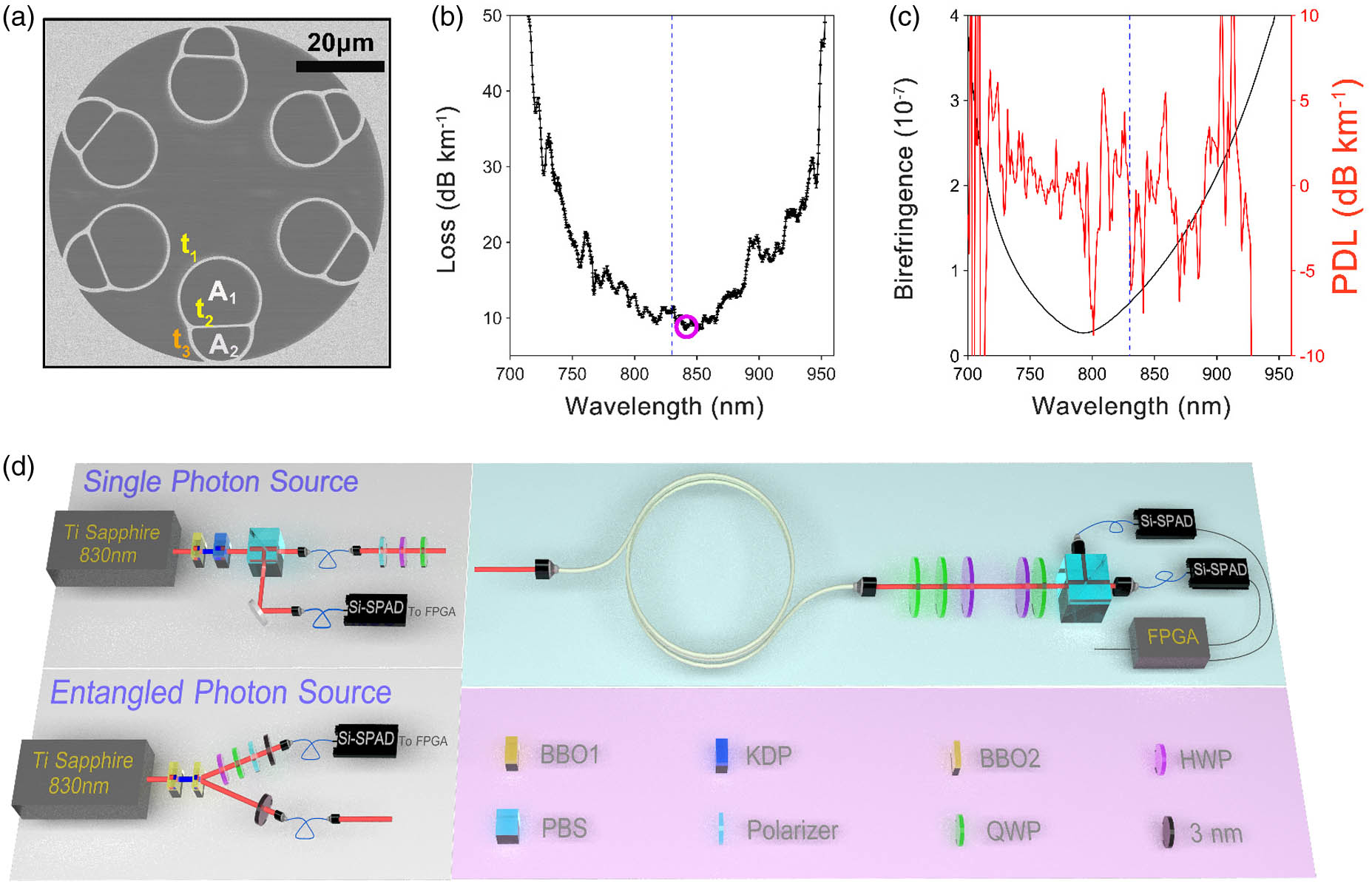
Figure 1.Characterization of the conjoined-tube fiber (CTF) and experimental setup for polarization quantum state transmission. (a) SEM image of the CTF. (b) Cut-back measured loss spectrum. The minimum loss and quantum transmission wavelength are marked by the purple circle and blue dashed line, respectively. (c) Simulated phase birefringence and PDL based on cross-section micrographs. (d) Experimental setup consisting of a heralded single-photon source (upper left), polarization entangled photon-pair source (lower left), and fiber-testing bench. BBO1/BBO2,
To achieve high modal purity in both spatial and polarization domains, low environmental sensitivity, and low CD, we incorporate the following three features into the geometry of our CTF. First, a big core-diameter-to-wavelength ratio () is adopted to guarantee a less than MF overlap with glass (Appendix A). Second, the flat glass membranes inside the CTs are arranged as far as possible away from the hollow core, rendering the polarization purity of the core mode not to be severely affected by Fano resonances existing around these structures [40]. Very recently, a remarkable feature of weak inter-polarization coupling (orders of magnitude weaker than the fundamental anisotropic RSL in solid-core glass fibers [41]) has been found in statically placed AR-HCFs [34]. This finding opens a new prospect for exploiting polarization resources in light transmission along AR-HCF.
Finite element method (FEM) simulations (COMSOL, Multiphysics) together with the fiber parameters extracted from the high-resolution SEM images yield the effective modal indices and confinement losses (CLs) of the two fundamental modes of orthogonal polarizations. Their differences give out the phase birefringence and polarization-dependent loss (PDL). For our CTF geometry, simulation reveals that the phase birefringence and PDL are at the levels of and , respectively [Fig. 1(c)]. Additionally, to attain a high spatial modal purity in our CTF, an optimized light in-coupling condition and the resonant filtering of higher-order modes (HOMs) induced by the first ring of cladding holes have been employed (Appendix B). Third, compared with our previously reported visible CTFs [35], the glass membrane thicknesses of this CTF ( and ) support a lower-order AR band at 800 nm, therefore yielding a wider transmission window and lower CD. The overall fiber loss also includes SSL and macro- and micro-bend losses (MABLs and MIBLs, respectively). The proportions of different loss components are shown in Appendix C.
3. POLARIZATION QUANTUM STATE TRANSMISSION
A. Single-Photon Polarization State Transmission
Having prepared a low-loss, high spatial modal purity, and low polarization degradation link in our CTF, we build a heralded single-photon source at 830 nm based on spontaneous parametric down conversion (SPDC) in a potassium dihydrogen phosphate (KDP) crystal. The pump light of the SPDC is generated in a -barium-borate (BBO) frequency doubling crystal (BBO1) driven by a Ti:sapphire pulsed laser (830 nm, 76 MHz). The down converted photons are spectrally filtered by 3 nm band-pass filters and spatially filtered by single-mode fibers (SMFs). The detected rate is about 30,000 counts per second (cps), and the heralding efficiency is 16%. The wavelength of our photon source matches well with the transmission window of our CTF, and the second-order correlation function is found to be , illustrating a very good single-photon attribute.
By arranging a linear polarizer (extinction ratio of over 40 dB) and two wave plates [half-wave plate (HWP) and quarter-wave plate (QWP)], we prepare the single photons on the six universal polarization states (H/V/D/A/R/L) and then inject them into the CTF [Fig. 1(d)] with an overall transmittance of above 60% (including in-coupling/out-coupling efficiencies and propagation loss along the fiber). At the output end of the CTF, after compensating for the polarization rotations, the single photons are projected onto three orthogonal bases [H/V, D/A, and R/L, i.e., mutually unbiased bases (MUBs)] by utilizing another set of HWP, QWP, and polarization beam splitter (PBS) (extinction ratio of over 30 dB). Two Si-SPADs record the coincidence counts, which are then analyzed by a field-programmable gate array (FPGA) (gating of 4 ns). The Si-SPADs used in our experiments offer a nominal detection efficiency of over 60%, a dark count rate of less than 150 cps, and random timing jitter of around 400 ps. To reduce the measurement error, all the coincidence experiments are undertaken twice by exchanging the two Si-SPADs.
We reconstruct the transmitted polarization states in the context of quantum state tomography (QST) [42]. The purity is defined as , and the fidelity between the experimental state () and theoretical state () is calculated by . In our experiments, the single-photon count rate after transmission is , the average fidelity between the transmitted and input states is , and the average purity is , as shown in Fig. 2(a). It is worth noting that all the fidelities secured in our measures are far above the classical limit of 2/3. As a comparison, we also conduct QST for the same sets of polarization states through a piece of SMF (Corning, HI780) with the same length. The average fidelity and purity of the transmitted states are about 0.975 and 0.997, respectively (Appendix D). Both fibers under test are statically and loosely placed on a table with a radius of . The results reveal that our CTF has the same level of polarization preserving capability as the SMF, due to the excellent spatial and polarization modal purities in a low MF-glass-overlapping fiber.
![]()
Figure 2.Experimental results of single-photon polarization state transmission. (a) Fidelities and purities of the six transmitted polarization states. The average fidelity and purity are
To further test our CTF link, a quantum process tomography (QPT) [43] is implemented to reconstruct the matrix of the transmitted photons with . Here, represents the Pauli bases in one-qubit cases. The identity process matrix denoted by should be a matrix, with and other elements zero. The process fidelity between the experimental result and the identity process is calculated by . As shown in Fig. 2(b), the QPT measurement yields a fidelity of 0.983 with respect to the identity process. In comparison, the QPT for the SMF link gives a fidelity of 0.972 (Appendix D). In addition, we also carry out QST and QPT over the CTF using a weak coherent source. The result validates the reliability of our measurements (Appendix E).
B. Polarization Entanglement Distribution
To demonstrate distribution of polarization entanglement over the CTF link, an entangled photon-pair source with a fidelity of 0.956 to the singlet state of has been constructed also at 830 nm via the type-II SPDC in BBO2 crystal [Fig. 1(d)]. One photon is measured locally, and the other is transmitted through the fiber link. The coincidence counts between the two Si-SPADs in the local node and at the output end of the tested fiber reach per 10 s.
The polarization correlations between the two photons are measured by projecting the local photon onto H, V, D, A states and rotating the polarization angle of the transmitted photon. As shown in Fig. 3(a), the visibilities of the polarization correlations after the CTF link are 97.1% and 97.8% in the H/V and D/A bases, respectively, well above the threshold value of 71% for the Bell inequality violation. We also reconstruct the entangled state with the density matrix shown in Fig. 3(b). The fidelity between the distributed entangled state and the initial state is 0.977. The asymmetry of the distributed state explains the differences in the total counts for different bases in Fig. 3(a). To highlight the quality of the distributed entanglement, we evaluate the Clauser–Horne–Shimony–Holt (CHSH) inequality by the S parameter [44], whose result of violates the classical limit of two by 41 standard deviations. All the above results confirm that polarization entanglement has been maintained very well across the full length of CTF. In combination with the above single-photon transmission tests, our experiments unambiguously prove that our CTF can be used as a reliable link for transmission of QI encoded in the polarization degree of freedom of photons.
![]()
Figure 3.Experimental results of single-photon polarization state transmission. (a) Polarization correlations between the local and transmitted photons. The visibilities in the H/V and D/A bases are measured to be 97.1% and 97.8%, respectively. (b) Density matrix of the distributed entangled state. The fidelity with respect to the initial state is 0.977.
4. SINGLE-PHOTON LOW-LATENCY TRANSMISSION
To demonstrate the intrinsic merit of HCF, we measure the CDs and group indices of short pieces of CTF and SMF using low-coherence interferometry. A free-space Mach–Zehnder interferometer, composed of a super-continuum source, two 50:50 plate beam splitters, two pairs of coupling lenses, two motorized stages, and an optical spectrum analyzer, is used with the CTF and SMF lengths of 20 cm and 5 cm, respectively [33]. As shown in Fig. 4(a), at 830 nm, our CTF has a lower dispersion than the SMF and almost the same (99.96%) speed of light as in vacuum. The errors produced in measurement and in polynomial fit are estimated and outlined. Such a low dispersion can be attributed to the low MF overlap with glass (Table 1 in Appendix A) as well as the wide transmission window [33,45] of the second-order AR window. The big core diameter relative to the wavelength (with the ratio of ) explains the reason for the faster light speed in our CTF than in the reported 19-cell PBG-HCF [36] (with a ratio of ). In contrast, the high CD and high latency in the SMF are fundamentally caused by the material properties of silica glass and TIR guidance.
![]()
Figure 4.Characterization of chromatic dispersion (CD), group index, and single-photon latency. (a) Measured CDs and group indices of a 20 cm long CTF and a 5 cm long SMF using a free-space Mach–Zehnder interferometer.
| Core Diameter to | MF Overlap | MF Overlap | MF Overlap with | ||
|---|---|---|---|---|---|
| This work | 830 | 35 | 1.4 | ||
| ARF1 [ | 1550 | 27 | 1 | ||
| NANF1 [ | 1550 | 21 | 4.4 | ||
| 37c PBGF [ | 22 | 50–500 |
Table 1. Comparison of Mode Field Overlaps of Four Different HCFs
To manifest the low-latency feature of our CTF link, we also build a single-photon time-of-flight measurement setup. The input photons are split into two routes, coupled into the two fibers with the same length (36.4 m), and then detected by two Si-SPADs. We use the heralded photons in the local Si-SPAD as the trigger to register the arrival time with a time stamp device (Swabian Instruments, with resolution of 10 ps). To eliminate the influence of electronic links, we carry out measurements twice with the two receiver Si-SPADs and cables being exchanged. As shown in Fig. 4(b), over a fiber distance of , a time leading of is accumulated in our CTF link, yielding a group index difference of . Here, is the speed of light in vacuum, is hypothesized, and 0.6 ns represents the uncertainty from the timing jitter in the two Si-SPADs. It is worth noting that the two measurements of group index difference in Figs. 4(a) and 4(b) agree well with each other.
5. CONCLUSION AND DISCUSSION
The quantum internet is one of the ultimate targets of QI science and technology. To realize this goal, reliable generation, transmission, manipulation, and detection of quantum states are the keystones. We deem that the high-fidelity single-photon polarization state transmission and polarization entanglement distribution through a CTF at Si-SPAD wavelengths as demonstrated in this work are just an early indication of a more versatile use of advanced AR-HCFs in QI processing with more degrees of freedom of photons. Apart from permitting qubits to fly with the fastest speed in the universe, AR-HCFs also provide an unprecedented way to exploit the resource of optical fibers associated with spatial/polarization modal purities and transmission windows in the visible region, both facilitating QI encoding in photons.
To realize the above functions, AR-HCFs have to be designed and fabricated deliberately. As shown in this proof-of-principle work, the flexibility provided by the cladding micro-structures in our CTF allows for simultaneously realizing low loss, high spatial modal purity, low polarization degradation, and a wide transmission window (so that dispersion is reduced) at 800 nm. Over a distance of 36.4 m, we have examined the CTF-based polarization quantum state transmission and have not observed any inferiority compared with conventional solid-core fiber links. Besides being used to transfer the polarization-encoded QI, our CTF also has the potential to support high-dimensional quantum state transmission in time and frequency modes due to its low CD and large transmission bandwidth.
While long distance CTF-based quantum communication is still waiting for more mature CTF fabrication, the performance of the current proof-of-concept experiment is indeed limited by a relatively high loss, which can be ascribed partly to the mismatched glass membrane thickness of and the MIBL. As analyzed above, the situation of in our CTF renders the third layer of glass wall not to contribute AR reflections at 830 nm. Once this issue is overcome (e.g., replacing by or ), FEM simulation shows that the CL can further decrease by (Appendix F). Additionally, micro-bending effects also contribute a significant portion of loss to the overall attenuation because of the big core-diameter-to-wavelength ratio. As suggested in our recent paper [35], improving fiber straightness by using a better polymer coating technique (e.g., “wet-on-dry” double coating) may be necessary in future refinement. At the time of this experiment, we have used a single-layer coating with a big segment modulus (35 MPa), probably causing high MIBL.
The low CD of less than 2 ps/(nm·km) demonstrated in our CTF can also be a valuable resource for quantum communications with reduced temporal spread of photons. Different from solid-core fiber, whose CD is dominated by material dispersion, the CD of HCF can be pronouncedly reduced by enlarging the transmission bandwidth. Moreover, the reduced CD will find applications in quantum-enhanced positioning and clock synchronization [46, 47], which is indispensable for a quantum network of clocks [48].
In summary, while the TIR guiding mechanism discovered by John Tyndall in 1870 liberated light propagation from the line-of-sight way, and the high transparency of purified silica glass discovered by Charles Kao in 1966 opened long distance fiber-optic applications, the development of HCF, which was triggered by Philip Russell’s idea of incorporating micro-structures into the cladding in 1991, led us to another leap of using optical fibers in a free-space-like but non-line-of-sight manner. Such a liberation is of crucial importance for harnessing photons as QI couriers.
APPENDIX A: SIMULATION OF MODE-FIELD OVERLAPS WITH GLASS AND GLASS–AIR INTERFACES
A unique characteristic of AR-HCF is that with a change in the ratio of the core diameter and wavelength, it allows a designer to adjust the strength of optical confinement and the amount of MF overlap with glass, which can be defined as with , the axial Poynting vector of the core mode. This physical quantity is related with fiber’s environmental sensitivities to temperature and stress, because external influences to a fiber are caused mainly through the thermo-optic and elasto-optic effects in silica glass.
Additionally, since the glass–air interfaces of HCFs contain intrinsic roughness from frozen-in surface capillary waves [
Using a finite element solver (COMSOL Multiphysics), we calculate the MF distributions and their overlaps with glass and interfaces. High-resolution SEM image provides fiber’s geometrical parameters. Excellent agreement between modelling and experiments has been achieved in our previous works [
![]()
Figure 5.Simulated MF overlapping coefficients with (a) glass and (b) interface for our CTF. The fundamental core modes with the two polarizations are calculated.
APPENDIX B: SIMULATION OF HIGHER-ORDER MODE LOSSES
In our photonic QI transmission experiments, preserving a high-purity spatial mode is of crucial importance. For this purpose, two measures have been taken. First, to match the fundamental mode of the CTF, the fiber launch condition is optimized with the in-coupling efficiency being greater than 80%. Second, the resonant HOM filtering effect [
![]()
Figure 6.Simulated (a) effective indices and (b) confinement losses of different orders of modes.
APPENDIX C: DECOMPOSITION OF CL, SSL, AND MACRO/MICRO-BEND LOSS
Both the CL and the SSL of our CTF can be simulated by using the FEM (COMSOL Multiphysics). To calculate the MABL, a conformal transformation technique with an equivalent refractive index distribution of in the fiber cross-section can be employed [
![]()
Figure 7.Comparison of experimentally measured and numerically calculated losses of our CTF.
APPENDIX D: TRANSMISSION OF SINGLE-PHOTON POLARIZATION STATES THROUGH A 36.4??M SMF
To compare the single-photon polarization properties of our CTF and standard silica core fiber, we mount a 36.4?m SMF (Corning, HI780) into our test apparatus using the 830?nm heralded single-photon source. This SMF has an MF diameter of and a loss of 3.0?dB/km at 850?nm. We prepare six universal single-photon polarization states using a combination of a polarizer, an HWP, and a QWP, before injecting them into the SMF. The coupling efficiency is optimized to be . After compensating for the polarization rotation, we implement MUB measurements on each state. Then we employ QST [
![]()
Figure 8.(a) Measured fidelities and purities of the six single-photon polarization states after transmission through a 36.4 m SMF. Error bars represent one standard deviation. (b) Process matrix (
A comparison between the tomography results of the SMF (Fig.?
APPENDIX E: TRANSMISSION OF SINGLE-PHOTON POLARIZATION STATES OVER CTF USING WEAK COHERENT SOURCE
For realistic reasons, the community of photonic QI processing has been used to employ classical weak coherent sources for mimicking single-photon Fock states [
![]()
Figure 9.(a) Measured fidelities and purities of the six single-photon polarization states after a 65.5 m CTF using weak coherent source. Error bars represent one standard deviation. (b) Process matrix (
APPENDIX F: INFLUENCE OF THE GLASS WALL THICKNESS t3
As discussed in the main text, the low-loss guidance of our CTF is partly degraded by the inappropriate glass wall thickness of , which fails to obey the AR reflecting condition at 830?nm. According to the formula for the th-order resonant wavelength [
References
[13] C. Monroe. Quantum information processing with atoms and photons. Nature, 416, 238-246(2002).
[17] P. St.J. Russell. Photonic-crystal fibers. J. Lightwave Technol., 24, 4729-4749(2006).
[31] G. T. Jasion, T. Bradley, K. Harrington, H. Sakr, Y. Chen, E. N. Fokoua, I. Davidson, A. Taranta, J. Hayes, D. Richardson, F. Poletti. Hollow core NANF with 0.28 dB/km attenuation in the C and L bands. Optical Fiber Communication Conference, Th4B.4(2020).
[39] H. Sakr, T. D. Bradley, Y. Hong, G. T. Jasion, J. R. Hayes, H. Kim, I. A. Davidson, E. N. Fokoua, Y. Chen, K. R. H. Bottrill, N. Taengnoi, P. Petropoulos, D. J. Richardson, F. Poletti. Ultrawide bandwidth hollow core fiber for interband short reach data transmission. Optical Fiber Communication Conference, Th4A.1(2019).
[51] T. D. Bradley, G. T. Jasion, J. R. Hayes, Y. Chen, L. Hooper, H. Sakr, M. Alonso, A. Taranta, A. Saljoghei, H. C. Mulvad, M. Fake, I. A. K. Davidson, N. V. Wheeler, E. N. Fokoua, W. Wang, S. R. Sandoghchi, D. J. Richardson, F. Poletti. Antiresonant hollow core fiber with 0.65 dB/km attenuation across the C and L telecommunication bands. European Conference on Optical Communication, PD3.1(2019).
[52] Y. Chen, H. C. H. Mulvad, S. R. Sandoghchi, E. Numkam, T. D. Bradley, J. R. Hayes, N. V. Wheeler, G. T. Jasion, S. U. Alam, F. Poletti, M. N. Petrovich, D. J. Richardson. First demonstration of low loss, bend insensitive 37-cell hollow-core photonic bandgap fiber at 1 μm for high power delivery applications. Conference on Lasers and Electro-Optics, STu4P.1(2016).
[54] D. Marcuse. Microdeformation losses of single-mode fibers. Appl. Opt., 23, 1082-1091(1984).
[55] E. N. Fokoua, Y. Chen, D. J. Richardson, F. Poletti. Microbending effects in hollow-core photonic bandgap fibers. European Conference on Optical Communication, Tu2F.3(2016).

Set citation alerts for the article
Please enter your email address
© Copyright 2018-2021 | Chinese Laser Press. All Rights Reserved 沪ICP备15018463号-20