
Lingyao Yu, Yuan Jia, Xujin Hu, Shaofei Wang, Hongyu Chen, Shuai Liu, Hongchang Deng, Maowen Wang, Jun Yin. Trapping and revolving micron particles by transformable line traps of optical tweezers[J]. Chinese Optics Letters, 2022, 20(5): 053801
- Chinese Optics Letters
- Vol. 20, Issue 5, 053801 (2022)
Abstract
1. Introduction
Optical tweezers have been greatly developed for their controllable manipulations of dielectric particles, biological cells, and other organelles that could be trapped, displaced, deformed, and even rotated[
In this paper, we proposed an alternative manipulation method of the transformable configurations between dual-line and single-line traps in optical line tweezers by using the transverse electromagnetic mode () laser source. We designed an optical path to simulate the generation of the astigmatic beams and line traps with a series of lenses and the rotational transformation with respect to the rotation angle of CLs. We also trapped, aligned, and revolved the spherical particles with various diameters with the line traps in experiment. Results of the focused line traps and the manipulated particles by the line traps at different rotation angles are also presented. The advantages of this novel tool of optical line tweezers for the particle manipulation are as follows. (1) The process for generation of the dual-line trap using the laser source and CLs loses much less energy than that using the fundamental mode laser source and the beam splitter and combiner[
2. Optical Design
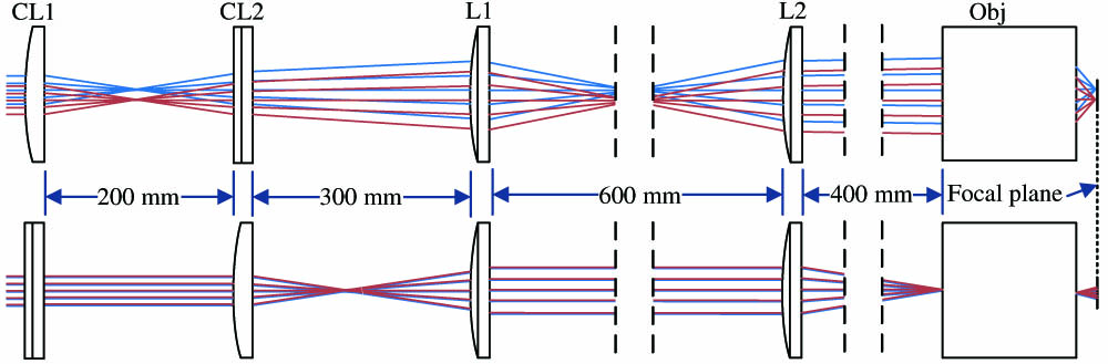
To capture the particles with the microscope of optical line tweezers, the shaped laser line before being sent into the microscope frame should be focused in the same plane from which the sample is imaged, which is difficult to realize in experiment without the optical design due to two factors: (1) the shaped laser line of which the two axes are divergent at different degrees is not the collimated beam; (2) it requires a long distance (at least 400 mm) between the last lens outside the microscope and the objective in the microscope. Thus, we firstly conducted the optical design in Zemax to facilitate the generation of the line traps in the focal plane of the objective. Figure 1 illustrates the optical rays passing through five optical elements including two CLs with the identical focal length of 100 mm, two plano-convex lenses with the focal lengths of 200 mm and 400 mm, respectively, and an objective with the magnification of 40 times in top view (top) and front view (bottom). The mode-like beam was used as the laser source and taken as dual Gaussian beams with the separation of 0.7 mm in the horizontal direction, waist radius of 0.75 mm, and divergent angle of 0.1° for each one. The first-order mode of the laser source provides a good performance for generation of dual-line traps and a longer single-line trap, compared to the fundamental mode. Two CLs, with cylindrical axes always perpendicular to each other and separated by a distance of the sum of each focal length, were applied to shape laser points into two astigmatic beams that diverge separately in both axes perpendicular to the optical axis. Two plano-convex lenses arranged in a lens system were used to increase the distance to the objective because of the requirement of a long distance from the external frame of the microscope to the entrance pupil of the objective. Compared to the objective of the larger magnification, generally, 100 × and higher numerical aperture (NA), i.e., , we applied the NA objective to increase the trapping region along the axial direction and enlarge the microscopic field of view, avoiding oil immersion. The top view (top) and the front view (bottom) in Fig. 1 show the case of generating dual-line traps: The mode-like laser beam was firstly focused to be two vertical lines parallel to each other and then diverged only in the horizontal direction away from the focal plane of the first CL (CL1) whose cylindrical axis was vertical; secondly, the horizontally diverged beams were focused and then diverged only in the vertical direction as passing through CL2, so as to form two astigmatic beams because each beam was focused twice in two perpendicular directions but at different focal planes of CL1 and CL2; finally, passing through two plano-convex lenses, these astigmatic beams were focused by the objective in different focal planes to realize the dual-line traps[
Sign up for Chinese Optics Letters TOC. Get the latest issue of Chinese Optics Letters delivered right to you!Sign up now
![]()
Figure 1.Illustration of optical design generating dual-line traps in top view (top) and front view (bottom). CL1 and CL2, cylindrical lenses; L1 and L2, plano-convex lenses; Obj, objective. Not to scale.
In non-sequential mode in Zemax, the configuration of various beam patterns in the focal plane of the objective was simulated by rotating CLs. Figure 2(a) shows the normalized intensity of the dual-line traps. By turning 20°, 90°, and 110° counterclockwise accordingly, the beam patterns are displayed in Figs. 2(b)–2(d), respectively. The dual-line traps in parallel started tilting as the rotation angle increased, during which the beam separation between lines decreased until merging the single-line trap at the rotation angle of 90°. Owing to the superposition of the dual partial lines, the single line in series pattern in Fig. 1(c) showed longer maximum value in red color than in other patterns. For this reason, we took of the maximum intensity of the single-line trap as the criterion for the normalized plot of the intensity distribution. The dimensions of the dual-line traps were around 40 µm in length, 1.1 µm in width, and 3.0 µm of the beam separation, and the length and width of the single-line trap were around 50 µm and 1.3 µm. In addition, simulation results showed that the focal lengths F1 and F2 for CL1 and CL2 could modify the length and width of the line traps. For example, in the case of generating dual-line traps, the lengths of both line traps were elongated as F2 was reduced, and the widths decreased as F1 was augmented.
![]()
Figure 2.Normalized intensity distribution of various line traps. (a) The dual-line traps and the line traps with the rotation angles of (b) 20°, (c) 90°, and (d) 110° counterclockwise. Scale bar: 10 µm.
3. Optical Experiments
Based on the simulation results, we shaped the laser beam and sent them into the Olympus inverted microscope (IX71) by replacing the fluorescence excitation source. Figure 3 shows the experimental setup for the laser line generation and the particles manipulation. The diode-pumped solid state (DPSS) laser beam with the central wavelength of 532 nm and the total power of 1.5 W was used to create dual lines with two perpendicular CLs and two plano-convex lenses as simulated in Zemax. Reflected by a dichroic mirror (DM), the beam was focused in the focal plane by the objective (UPLFLN, , Olympus) where the sample was located. Two CLs with two lens mounts fixed in a tube could be automatically controlled to rotate at a certain rotation rate. The sample plane was illuminated by the condensed white light and imaged by the same objective focusing the line traps into the digital CCD camera (DP72, Olympus) through the DM and a short pass filter.
![]()
Figure 3.Schematic of optical setup for the line traps generation and particles manipulation. DM, dichroic mirror; PD, petri dish; UL, uniform light.
4. Results and Discussion
The laser source sent directly into the objective without any lens for beam shaping was imaged in grayscale, as shown in Fig. 4(a). The deionized water was firstly filled into the petri dish (PD) as the sample for the clear observation of the laser source with the power of 1.5 mW in the focal plane. All images in Fig. 4 were captured by the CCD camera with minimum exposure time of 23 µs/frame so that all the intensity higher than the threshold would be drawn in the saturation state, the white color. Passing through a series of lenses and the objective instead, the laser source became focused lines whose configurations were arranged with respect to the rotation angles of two CLs. Figures 4(b)–4(e) show four images of focused lines at the counterclockwise rotation angles of 0°, 20°, 90°, and 110°, respectively. The rotation angle of 0° is the case where dual lines denote a pair of opposite sides of the rectangle, which leads to the maximum distance between dual lines. The lengths of dual lines were measured to be about 38 µm and 25 µm, the widths are 3.8 µm and 2.4 µm, and the beam separation is around 4.1 µm. Compared with the dual lines in Fig. 4(b), the single line of Fig. 4(d) in the white color manifested the longer effective length suited well to the trend of the simulation results. Due to the asymmetric distribution of the laser source, represented by Fig. 4(a), one of the dual lines was larger than the other one accordingly in Fig. 4(b). Despite the mode-like beam, we still obtained the transformable dual-line and single-line traps to manipulate the beads efficiently. That would be better if the line traps under symmetrical conditions were used for manipulation, but the symmetrical line traps might not greatly improve the capture efficiency and ability because the mechanism of the transformation was still unchanged, and the intensity difference of two beam points was not that much. As the rotation angle increased, dual lines came close to each other and began to form the two opposite sizes of a parallelogram until they overlapped into a single line, as shown in Fig. 4(d). The length and width of the single line were about 30 µm and 2.8 µm, as shown in Fig. 4(d). The ratio of the length to the width, whether it belongs to the dual lines or the single line, is almost kept to be around 11:1, which depends on the focal lengths of all the lenses. As the rotation angle increased from 90°, the single line was divided into two lines, of which the beam separation increased until the maximum distances were at the rotation angle of 180°. Although the original mode-like laser beam is not so symmetric that one line of generated dual lines is stronger than the other one, the micron particles could still be trapped and manipulated effectively in our system.
![]()
Figure 4.Microscopic images of (a) the laser source and focused lines at the rotation angles of (b) 0°, (c) 20°, (d) 90°, and (e) 110°. Scale bar: 10 µm.
For micro-manipulations, the sample of polystyrene microbeads suspended in the deionized water was prepared. Instead of dropping a droplet of the sample on a piece of coverglass, we employed the coverglass-bottom PD containing a ‘layer’ of the sample to decrease the surface tension of the droplet. The refractive index and the density of polystyrene microbeads at room temperature are 1.59 and , and the corresponding parameters of the water are 1.33 and , respectively. The power of the trapping beams on the sample that increased to 120 mW was used for manipulation in experiment. Another set of DMs and the filter were chosen to prevent the transmitted laser source of the wavelength at 532 nm and allow other visible light into the CCD camera. Intuitively, the number of aligned particles depends on the length of the line traps, which means it equals the length of the line traps divided by the diameter of particles as the experimental results in Ref. [12]. In theory, the particles could be trapped and aligned by the potential well as the dragging force is larger than the viscous force from the solution[
![]()
Figure 5.Microscopic images for particles sizes of (a) 5 µm, (b) 10 µm, (c) 15 µm, and (d) 20 µm trapped by the dual lines and for particles sizes of (e) 5 µm, (f) 10 µm, (g) 15 µm, and (h) 20 µm trapped by the single line. Scale bar: 10 µm.
If one would manipulate the same number of small particles with the single-line and dual-line traps, respectively, three points might be satisfied: (1) the particle solution could be diluted to decrease the number of beads in the unit volume to insure the sparse distribution of these beads around the line traps; (2) the critical rotation rate that the beads could rotate as fast as the line traps but not escape from them could be achieved to avoid capturing more beads by the increased trapping force from the dual-line to single-line traps; (3) we firstly capture the beads by using the dual-line trap and then rotate the laser line to revolve these beads at the critical rotation rate until the single-line trap was formed.
The trapped particles of different diameters also moved with the trapping lines whose configuration was determined by the rotation angle of two CLs. Three images of the aligned particles with 20 µm diameter are displayed in Figs. 6(a)–6(c) when the counterclockwise rotation angle was 0°, 20°, and 60°, respectively. The green lines denoting trapping lines for manipulation were actually eliminated in front of the CCD camera. The experimental video (Visualization 1) for the motion of the particles from Figs. 6(a)–6(c) is available online. The objects could be almost stably trapped and rotated with the transformable line traps when the angular velocity is 0.26 rad/s or slower because of the balance among the torque force of line traps, centrifugal force, and viscous force of water. But, if the angular velocity were too high, the beads would escape from the potential of line traps. Compared with the trapping area for the low-refractive-index particles in the dual-line optical tweezers[
![]()
Figure 6.Images of the particles (20 µm diameter) revolved as the rotation angle of (a) 0°, (b) 20°, and (c) 60°. Green lines denote trapping lines. Scale bar: 20 µm.
5. Conclusion
We proposed to create transformable configurations between dual-line and single-line traps of optical line tweezers. We were able to simulate the line traps with the laser source to optimize the length and width of line traps. Then, we built up the optical system for the laser line generation and particle manipulation. It has been demonstrated that the spherical particles with diameters ranging from 5 µm to 20 µm could be trapped, aligned, and revolved with the line traps in experiment. The periodical trapping forces generated by the rotational configurations of transformable line traps can be used as a new tool for the measurement of mechanical properties of soft particles and biological cells.
References
[1] L. Gong, X. Zhang, Z. Zhu, G. Rui, J. He, Y. Cui, B. Gu. Femtosecond laser trapping dynamics of two-photon absorbing hollow-core nanoparticles. Chin. Opt. Lett., 18, 081901(2020).
[2] J. Hong, X. Zhou, R. Zhuang, W. Peng, J. Liu, A. Liu, Q. Wang. Nanoparticle trapping by counter-surface plasmon polariton lens. Chin. Opt. Lett., 20, 023601(2022).
[3] J. Pu, K. Zeng, Y. Wu, D. Xiao. Miniature optical force levitation system. Chin. Opt. Lett., 20, 013801(2022).
[4] P. J. Bronkhorst, G. J. Streekstra, J. Grimbergen, E. J. Nijhof, J. J. Sixma, G. J. Brakenhoff. A new method to study shape recovery of red blood cells using multiple optical trapping. Biophys. J., 69, 1666(1995).
[5] S. Rancourt-Grenier, M. T. Wei, J. J. Bai, A. Chiou, P. P. Bareil, P. L. Duval, Y. Sheng. Dynamic deformation of red blood cell in dual-trap optical tweezers. Opt. Express, 18, 10462(2010).
[6] H. Lu, Y. Wu, W. Xie, Q. Tang, C. Han, Y. Liu. Photothermal biological effects of monomeric erythrocyte using optical tweezers. Chin. Opt. Lett., 17, 061701(2019).
[7] J. Lamstein, A. Bezryadina, D. Preece, J. C. Chen, Z. Chen. Optical tug-of-war tweezers: shaping light for dynamic control of bacterial cells. Chin. Opt. Lett., 15, 030010(2017).
[8] Y. Zhang, Z. Liu, J. Yang, L. Yuan. Four-core optical fiber micro-hand. J. Light. Technol., 30, 1487(2012).
[9] H. Deng, Y. Zhang, T. Yuan, X. Zhang, Y. Zhang, Z. Liu, L. Yuan. Fiber-based optical gun for particle shooting. ACS Photonics, 4, 642(2017).
[10] X. Zhang, S. Yang, L. Yuan. Optical-fiber-based powerful tools for living cell manipulation [Invited]. Chin. Opt. Lett., 17, 090603(2019).
[11] G. B. Liao, P. B. Bareil, Y. Sheng, A. Chiou. One-dimensional jumping optical tweezers for optical stretching of bi-concave human red blood cells. Opt. Express, 16, 1996(2008).
[12] K. B. Roth, K. B. Neeves, J. Squier, D. W. Marr. Imaging of a linear diode bar for an optical cell stretcher. Biomed. Opt. Express, 6, 807(2015).
[13] R. Dasgupta, S. K. Mohanty, P. K. Gupta. Controlled rotation of biological microscopic objects using optical line tweezers. Biotechnol. Lett., 25, 1625(2003).
[14] I. Sraj, C. D. Eggleton, R. Jimenez, E. Hoover, J. Squier, J. Chichester, D. W. Marr. Cell deformation cytometry using diode-bar optical stretchers. J. Biomed. Opt., 15, 047010(2010).
[15] B. Ma, B. Yao, F. Peng, S. Yan, M. Lei, R. Rupp. Optical sorting of particles by dual-channel line optical tweezers. J. Opt., 14, 105702(2012).
[16] E. Spyratou, E. A. Mourelatou, A. Georgopoulos, C. Demetzos, M. Makropoulou, A. A. Serafetinides. Line optical tweezers: a tool to induce transformations in stained liposomes and to estimate shear modulus. Colloids Surf. A Physicochem. Eng. Asp., 349, 35(2009).
[17] E. Spyratou, E. Cunaj, G. Tsigaridas, E. A. Mourelatou, C. Demetzos, A. A. Serafetinides, M. Makropoulou. Measurements of liposome biomechanical properties by combining line optical tweezers and dielectrophoresis. J. Liposome Res., 25, 202(2015).
[18] S. K. Mohanty, R. S. Verma, P. K. Gupta. Trapping and controlled rotation of low-refractive-index particles using dual line optical tweezers. Appl. Phys. B, 87, 211(2007).
[19] T. Sawetzki, C. D. Eggleton, D. W. M. Marr. Cell elongation via intrinsic antipodal stretching forces. Phys. Rev. E, 86, 061901(2012).

Set citation alerts for the article
Please enter your email address
© Copyright 2018-2021 | Chinese Laser Press. All Rights Reserved 沪ICP备15018463号-20