• High Power Laser Science and Engineering
  • Vol. 7, Issue 3, 03000e54 (2019)
Colin N. Danson1、2、3、†, Constantin Haefner4、5、6, Jake Bromage7, Thomas Butcher8, Jean-Christophe F. Chanteloup9, Enam A. Chowdhury10, Almantas Galvanauskas11, Leonida A. Gizzi12, Joachim Hein13, David I. Hillier1、3, Nicholas W. Hopps1、3, Yoshiaki Kato14, Efim A. Khazanov15, Ryosuke Kodama16, Georg Korn17, Ruxin Li18, Yutong Li19, Jens Limpert20、21、22, Jingui Ma23, Chang Hee Nam24, David Neely8、25, Dimitrios Papadopoulos9, Rory R. Penman1, Liejia Qian23, Jorge J. Rocca26, Andrey A. Shaykin15, Craig W. Siders4, Christopher Spindloe8, Sándor Szatmári27, Raoul M. G. M. Trines8, Jianqiang Zhu28, Ping Zhu28, and Jonathan D. Zuegel7
Author Affiliations
  • 1AWE, Aldermaston, Reading, UK
  • 2OxCHEDS, Clarendon Laboratory, Department of Physics, University of Oxford, Oxford, UK
  • 3CIFS, Blackett Laboratory, Imperial College, London, UK
  • 4NIF & Photon Science Directorate, Lawrence Livermore National Laboratory, Livermore, USA
  • 5Fraunhofer Institute for Laser Technology (ILT), Aachen, Germany
  • 6Chair for Laser Technology LLT, RWTH Aachen University, Aachen, Germany
  • 7University of Rochester, Laboratory for Laser Energetics, Rochester, USA
  • 8Central Laser Facility, STFC Rutherford Appleton Laboratory, Chilton, Didcot, UK
  • 9LULI, CNRS, CEA, Sorbonne Universités, École Polytechnique, Institut Polytechnique de Paris, Palaiseau, France
  • 10Department of Physics, The Ohio State University, Columbus, USA
  • 11Centre for Ultrafast Optical Science, University of Michigan, Ann Arbor, USA
  • 12Intense Laser Irradiation Laboratory, Istituto Nazionale di Ottica (INO), CNR, Pisa, Italy
  • 13Institute of Optics and Quantum Electronics, Friedrich-Schiller-University Jena and Helmholtz Institute, Jena, Germany
  • 14The Graduate School for the Creation of New Photonics Industries, Nishiku, Hamamatsu, Japan
  • 15Institute of Applied Physics, Russian Academy of Sciences, Nizhny Novgorod, Russia
  • 16Institute of Laser Engineering, Osaka University, Suita, Osaka, Japan
  • 17ELI-Beamlines, Institute of Physics, Czech Academy of Sciences, Prague, Czech Republic
  • 18State Key Laboratory of High Field Laser Physics, Shanghai Institute of Optics and Fine Mechanics, Chinese Academy of Sciences, Shanghai 201800, China
  • 19National Laboratory for Condensed Matter Physics, Institute of Physics, Chinese Academy of Sciences, Beijing 100190, China
  • 20Institute for Applied Physics (IAP) at Friedrich-Schiller-University Jena, Jena, Germany
  • 21Helmholtz Institute Jena, Jena, Germany
  • 22Fraunhofer Institute for Applied Optics and Precision Engineering (IOF), Jena, Germany
  • 23Key Laboratory for Laser Plasma (Ministry of Education), School of Physics and Astronomy, Shanghai Jiao Tong University, Shanghai 200240, China
  • 24Centre for Relativistic Laser Science (CoReLS), Institute for Basic Science, Department of Physics and Photon Science, Gwangju Institute of Science and Technology, Gwangju, South Korea
  • 25SUPA, Department of Physics, University of Strathclyde, Glasgow, UK
  • 26Colorado State University, Fort Collins, Colorado, USA
  • 27Department of Experimental Physics, University of Szeged, Szeged, Hungary
  • 28National Laboratory on High Power Laser and Physics, Shanghai Institute of Optics and Fine Mechanics, Chinese Academy of Sciences, Shanghai 201800, China
  • show less
    DOI: 10.1017/hpl.2019.36 Cite this Article Set citation alerts
    Colin N. Danson, Constantin Haefner, Jake Bromage, Thomas Butcher, Jean-Christophe F. Chanteloup, Enam A. Chowdhury, Almantas Galvanauskas, Leonida A. Gizzi, Joachim Hein, David I. Hillier, Nicholas W. Hopps, Yoshiaki Kato, Efim A. Khazanov, Ryosuke Kodama, Georg Korn, Ruxin Li, Yutong Li, Jens Limpert, Jingui Ma, Chang Hee Nam, David Neely, Dimitrios Papadopoulos, Rory R. Penman, Liejia Qian, Jorge J. Rocca, Andrey A. Shaykin, Craig W. Siders, Christopher Spindloe, Sándor Szatmári, Raoul M. G. M. Trines, Jianqiang Zhu, Ping Zhu, Jonathan D. Zuegel. Petawatt and exawatt class lasers worldwide[J]. High Power Laser Science and Engineering, 2019, 7(3): 03000e54 Copy Citation Text show less
    The historical journey to multi-petawatt ultra-short-pulse laser facilities.
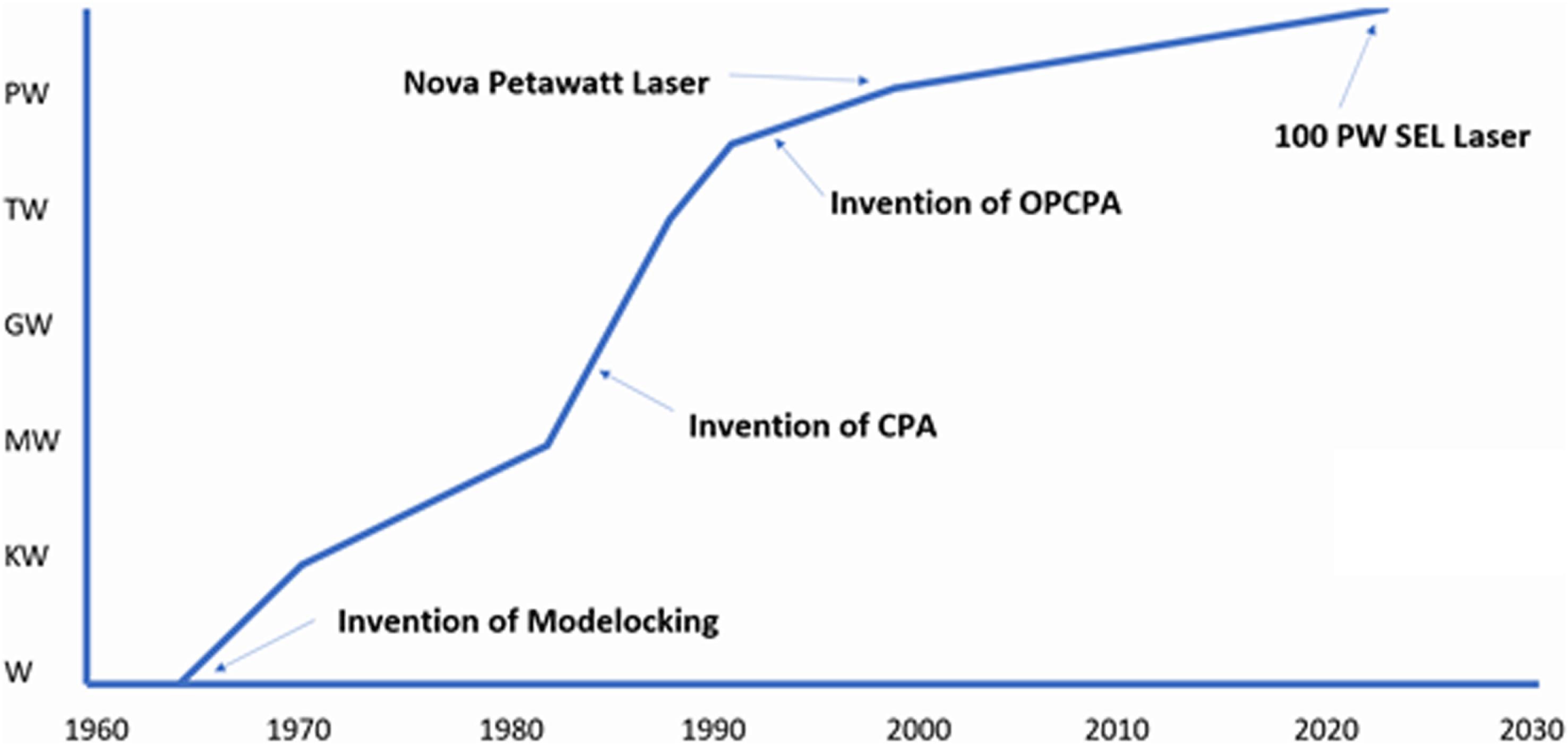
    Fig. 1. The historical journey to multi-petawatt ultra-short-pulse laser facilities.
    The 100 TW P102 laser system at CEA Limeil-Valenton, France (picture courtesy of CEA).
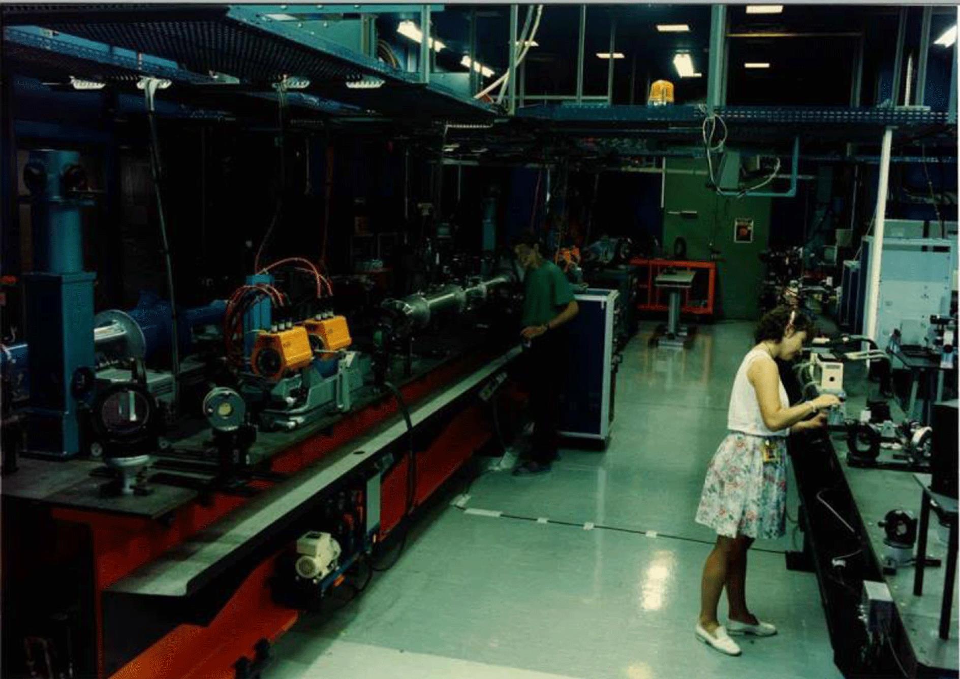
    Fig. 2. The 100 TW P102 laser system at CEA Limeil-Valenton, France (picture courtesy of CEA).
    The Vulcan 100 TW laser from the early/mid-1990s showing the first ever single-pass CPA compressor system with one grating in air (centre) and the second in vacuum (bottom right) (picture courtesy of STFC Rutherford Appleton Laboratory).
    Fig. 3. The Vulcan 100 TW laser from the early/mid-1990s showing the first ever single-pass CPA compressor system with one grating in air (centre) and the second in vacuum (bottom right) (picture courtesy of STFC Rutherford Appleton Laboratory).
    Inside the Nova Petawatt compressor chamber (picture courtesy of LLNL).
    Fig. 4. Inside the Nova Petawatt compressor chamber (picture courtesy of LLNL).
    NIF ARC compressor gratings during final alignment (picture courtesy of LLNL).
    Fig. 5. NIF ARC compressor gratings during final alignment (picture courtesy of LLNL).
    The Advanced Beam Laboratory at Colorado State University (picture courtesy of Colorado State University).
    Fig. 6. The Advanced Beam Laboratory at Colorado State University (picture courtesy of Colorado State University).
    The BELLA laser facility, the world’s first 1 Hz petawatt laser (picture courtesy of Lawrence Berkeley National Laboratory).
    Fig. 7. The BELLA laser facility, the world’s first 1 Hz petawatt laser (picture courtesy of Lawrence Berkeley National Laboratory).
    The Orion laser facility (picture courtesy of AWE).
    Fig. 8. The Orion laser facility (picture courtesy of AWE).
    The SCAPA facility at the University of Strathclyde (picture courtesy of University of Strathclyde).
    Fig. 9. The SCAPA facility at the University of Strathclyde (picture courtesy of University of Strathclyde).
    The Apollon laser at Orme des Merisiers (picture courtesy of Apollon).
    Fig. 10. The Apollon laser at Orme des Merisiers (picture courtesy of Apollon).
    The VEGA 3 laser facility at the University of Salamanca (picture courtesy of the University of Salamanca).
    Fig. 11. The VEGA 3 laser facility at the University of Salamanca (picture courtesy of the University of Salamanca).
    The L3 HAPLS laser was fully commissioned at LLNL before being shipped and re-installed at ELI-Beamlines (picture courtesy of LLNL).
    Fig. 12. The L3 HAPLS laser was fully commissioned at LLNL before being shipped and re-installed at ELI-Beamlines (picture courtesy of LLNL).
    The two 10 PW lasers installed in the ELI-NP facility (picture courtesy of ELI-NP).
    Fig. 13. The two 10 PW lasers installed in the ELI-NP facility (picture courtesy of ELI-NP).
    The SULF Prototype laser during final commissioning before being transferred to the SULF building (picture courtesy of SIOM).
    Fig. 14. The SULF Prototype laser during final commissioning before being transferred to the SULF building (picture courtesy of SIOM).
    The GEKKO XII (right) and LFEX (left) lasers at ILE, Osaka University, Japan (picture courtesy of Osaka University).
    Fig. 15. The GEKKO XII (right) and LFEX (left) lasers at ILE, Osaka University, Japan (picture courtesy of Osaka University).
    The multi-petawatt laser facility at CoReLS, South Korea (picture courtesy of CoReLS).
    Fig. 16. The multi-petawatt laser facility at CoReLS, South Korea (picture courtesy of CoReLS).
    Geographic distribution of high-peak-power lasers (top). Diameter of circle is logarithmically proportional to peak laser power and circle colour is chosen for graphical clarity. Evolution of high-peak-power lasers (${>}$100 GW) in the world over the last fifty years (bottom). Systems that are currently operating are shown as circles with solid borders; systems that were operating in the past but are now de-activated are shown as octagons with solid borders; and systems actively funded and being built are shown as circles with dashed borders. The diameter of the symbol is logarithmically proportional to laser pulse energy and the colour indicates the laser media used in the final amplifiers: Ti:sapphire (red), Nd:glass (grey), Yb:X (orange), Cr:X (yellow), optical parametric amplification (purple-blue), or gas (pink). As of early 2019, no high-power system has exceeded the 10 PW limit, even though there are several funded projects underway in Europe and Asia to break this barrier.
    Fig. 17. Geographic distribution of high-peak-power lasers (top). Diameter of circle is logarithmically proportional to peak laser power and circle colour is chosen for graphical clarity. Evolution of high-peak-power lasers (${>}$100 GW) in the world over the last fifty years (bottom). Systems that are currently operating are shown as circles with solid borders; systems that were operating in the past but are now de-activated are shown as octagons with solid borders; and systems actively funded and being built are shown as circles with dashed borders. The diameter of the symbol is logarithmically proportional to laser pulse energy and the colour indicates the laser media used in the final amplifiers: Ti:sapphire (red), Nd:glass (grey), Yb:X (orange), Cr:X (yellow), optical parametric amplification (purple-blue), or gas (pink). As of early 2019, no high-power system has exceeded the 10 PW limit, even though there are several funded projects underway in Europe and Asia to break this barrier.
    The current high-energy/high-power lasers globally (those that are operational represented by circles with continuous borders; those under construction represented by circles with dashed borders; or those that are decommissioned represented by octagons; with colour indicating the laser media of the final amplifier stage – defined in the legend in Figure 17).
    Fig. 18. The current high-energy/high-power lasers globally (those that are operational represented by circles with continuous borders; those under construction represented by circles with dashed borders; or those that are decommissioned represented by octagons; with colour indicating the laser media of the final amplifier stage – defined in the legend in Figure 17).
    Cumulative peak power of operational (green columns) and in construction (orange columns) high-peak power (${>}$0.1 PW) laser systems worldwide by area.
    Fig. 19. Cumulative peak power of operational (green columns) and in construction (orange columns) high-peak power (${>}$0.1 PW) laser systems worldwide by area.
    Peak power versus average power of high-peak-power, single-aperture laser systems and its primary pump lasers.
    Fig. 20. Peak power versus average power of high-peak-power, single-aperture laser systems and its primary pump lasers.
    Cumulative average power of operational (green columns) and in construction (orange columns) petawatt class lasers (${>}$0.1 PW) lasers across the world.
    Fig. 21. Cumulative average power of operational (green columns) and in construction (orange columns) petawatt class lasers (${>}$0.1 PW) lasers across the world.
    The PEARL OPCPA laser facility at the Institute of Applied Physics, Russian Academy of Sciences (picture courtesy of the Institute of Applied Physics).
    Fig. 22. The PEARL OPCPA laser facility at the Institute of Applied Physics, Russian Academy of Sciences (picture courtesy of the Institute of Applied Physics).
    A schematic of the SEL (Station of Extreme Light) 100 PW laser facility under construction in Shanghai (picture courtesy of SIOM).
    Fig. 23. A schematic of the SEL (Station of Extreme Light) 100 PW laser facility under construction in Shanghai (picture courtesy of SIOM).
    Diagram illustrating the Compression after Compressor Approach (CafCA) (NP – nonlinear plate, CM – chirped mirror, BC – beam cleaner: pinhole spatial filter[173] or free-space propagation[174]).
    Fig. 24. Diagram illustrating the Compression after Compressor Approach (CafCA) (NP – nonlinear plate, CM – chirped mirror, BC – beam cleaner: pinhole spatial filter[173] or free-space propagation[174]).
    Comparison of Raman amplification for two different parameter configurations, to demonstrate the importance of controlling long-wavelength laser-plasma instabilities. The results displayed are based on numerical simulations originally by Trines et al.[183].
    Fig. 25. Comparison of Raman amplification for two different parameter configurations, to demonstrate the importance of controlling long-wavelength laser-plasma instabilities. The results displayed are based on numerical simulations originally by Trines et al.[183].
    The HAPLS laser is compact and only 17 m long and 4 m wide. The power amplifiers that use helium gas cooling are on the rear table and the front ends are on the front table.
    Fig. 26. The HAPLS laser is compact and only 17 m long and 4 m wide. The power amplifiers that use helium gas cooling are on the rear table and the front ends are on the front table.
    In MPE mode, the same stored energy is extracted from the gain medium over multiple, low-fluence pulses versus extracting the energy in a single, high-fluence pulse. The extraction time in the MPE mode must be less than the storage lifetime.
    Fig. 27. In MPE mode, the same stored energy is extracted from the gain medium over multiple, low-fluence pulses versus extracting the energy in a single, high-fluence pulse. The extraction time in the MPE mode must be less than the storage lifetime.
    Left: Net efficiency (quantum defect $\times$ indirect CPA efficiency $\times$ electro-to-optical efficiency) versus gain lifetime of various laser gain media. For the Ti:sapphire case, $\unicode[STIX]{x1D702}_{\text{ICPA}}$ is 0.38 while for the other cases, which use direct CPA designs, $\unicode[STIX]{x1D702}_{\text{ICPA}}$ is unity. Laser media were down-selected for net efficiency (${>}$50%) and diode pumping suitability (gain lifetime ${>}$1 ms). Right: Extraction efficiency (stimulated emission rate divided by the sum of stimulated emission rate and spontaneous decay rate). In multi-pulse extraction, higher repetition rates (while maintaining the extraction fluence) are beneficial to the overall wall plug efficiency, i.e., the repetition rate determines the overall wall plug efficiency.
    Fig. 28. Left: Net efficiency (quantum defect $\times$ indirect CPA efficiency $\times$ electro-to-optical efficiency) versus gain lifetime of various laser gain media. For the Ti:sapphire case, $\unicode[STIX]{x1D702}_{\text{ICPA}}$ is 0.38 while for the other cases, which use direct CPA designs, $\unicode[STIX]{x1D702}_{\text{ICPA}}$ is unity. Laser media were down-selected for net efficiency (${>}$50%) and diode pumping suitability (gain lifetime ${>}$1 ms). Right: Extraction efficiency (stimulated emission rate divided by the sum of stimulated emission rate and spontaneous decay rate). In multi-pulse extraction, higher repetition rates (while maintaining the extraction fluence) are beneficial to the overall wall plug efficiency, i.e., the repetition rate determines the overall wall plug efficiency.
    LLNL’s BAT laser is envisioned to be capable of delivering up to 300 kW of 10 kHz, 30 J, 100 fs laser pulses.
    Fig. 29. LLNL’s BAT laser is envisioned to be capable of delivering up to 300 kW of 10 kHz, 30 J, 100 fs laser pulses.
    Schematic of the DiPOLE cryo-amplifier concept. Graded index Yb:YAG ceramic slabs are cooled to cryogenic temperatures (150 K) using a high-pressure, high-speed cryogenically cooled helium flow.
    Fig. 30. Schematic of the DiPOLE cryo-amplifier concept. Graded index Yb:YAG ceramic slabs are cooled to cryogenic temperatures (150 K) using a high-pressure, high-speed cryogenically cooled helium flow.
    Jena 16-channel filled aperture system.
    Fig. 31. Jena 16-channel filled aperture system.
    Palaiseau XCAN tiled-aperture system: Yb-doped fibres fluorescence for 19 out of 61 channels. Insert: laserhead with 35 fibres inserted.
    Fig. 32. Palaiseau XCAN tiled-aperture system: Yb-doped fibres fluorescence for 19 out of 61 channels. Insert: laserhead with 35 fibres inserted.
    Coherent pulse stacking amplification (CPSA).
    Fig. 33. Coherent pulse stacking amplification (CPSA).
    Divided pulse amplification (DPA).
    Fig. 34. Divided pulse amplification (DPA).
    (a) Collinear phase-matching. (b) Conventional wavelength-insensitive non-collinear phase-matching. (c) Temperature-insensitive non-collinear phase-matching with signal angular dispersion. The second rows in (a) to (c) show the normalized gain versus temperature and wavelength. (d) Measured signal efficiency versus temperature deviation for several non-collinear angles. $\unicode[STIX]{x1D6FC}=5.8^{\circ }$ and $6.8^{\circ }$ correspond to non-collinear phase-matching with signal angular dispersion, while $\unicode[STIX]{x1D6FC}=1.2^{\circ }$ corresponds to wavelength-insensitive non-collinear phase-matching. (e) Measured spectra of amplified signals with different amounts of angular dispersion when $\unicode[STIX]{x1D6FC}=5.8^{\circ }$.
    Fig. 35. (a) Collinear phase-matching. (b) Conventional wavelength-insensitive non-collinear phase-matching. (c) Temperature-insensitive non-collinear phase-matching with signal angular dispersion. The second rows in (a) to (c) show the normalized gain versus temperature and wavelength. (d) Measured signal efficiency versus temperature deviation for several non-collinear angles. $\unicode[STIX]{x1D6FC}=5.8^{\circ }$ and $6.8^{\circ }$ correspond to non-collinear phase-matching with signal angular dispersion, while $\unicode[STIX]{x1D6FC}=1.2^{\circ }$ corresponds to wavelength-insensitive non-collinear phase-matching. (e) Measured spectra of amplified signals with different amounts of angular dispersion when $\unicode[STIX]{x1D6FC}=5.8^{\circ }$.
    Temperature-dependent emission cross-sections of Tm:YAG.
    Fig. 36. Temperature-dependent emission cross-sections of Tm:YAG.
    Illustration of sources of contrast issues.
    Fig. 37. Illustration of sources of contrast issues.
    Schematic of the nonlinear Fourier filter.
    Fig. 38. Schematic of the nonlinear Fourier filter.
    (a) Schematic illustrating the operation principle of an ellipsoidal focusing plasma mirror to increase the intensity by a factor of five. (b) Input laser focal spot spatial-intensity distributions using $f/3$ illumination at 1053 nm and (c) the output spot image obtained, demonstrating a demagnification of $1/3$ in this ellipsoidal geometry[318].
    Fig. 39. (a) Schematic illustrating the operation principle of an ellipsoidal focusing plasma mirror to increase the intensity by a factor of five. (b) Input laser focal spot spatial-intensity distributions using $f/3$ illumination at 1053 nm and (c) the output spot image obtained, demonstrating a demagnification of $1/3$ in this ellipsoidal geometry[318].
    The schematic of a STRIPED FISH apparatus for single-shot complete spatiotemporal pulse measurement (reproduced from Ref. [353]).
    Fig. 40. The schematic of a STRIPED FISH apparatus for single-shot complete spatiotemporal pulse measurement (reproduced from Ref. [353]).
    (a) Schematic diagram depicting an angular-resolving escaping electron diagnostic which is based on injecting Cherenkov light[380] into an optical fibre array surrounding the interaction, as shown in (b). The diagnostic is capable of operating at repetition rates of MHz and, by encoding the electron flux into an optical signal within a fibre, it can be readily transported away from the interaction area, enabling the sensitive detector and digitizing electronics to be located far from the interaction and within an EMP-shielded enclosure giving high-quality data in (c).
    Fig. 41. (a) Schematic diagram depicting an angular-resolving escaping electron diagnostic which is based on injecting Cherenkov light[380] into an optical fibre array surrounding the interaction, as shown in (b). The diagnostic is capable of operating at repetition rates of MHz and, by encoding the electron flux into an optical signal within a fibre, it can be readily transported away from the interaction area, enabling the sensitive detector and digitizing electronics to be located far from the interaction and within an EMP-shielded enclosure giving high-quality data in (c).
    A 100 mm silicon wafer that has been coated with 100 nm low-stress silicon nitride and then processed using optical lithography and silicon etching to produce target arrays for the Gemini laser at RAL. Target flatness characterized to ${ variation over the open apertures. 16 arrays produce 400 targets per wafer (picture courtesy of STFC Rutherford Appleton Laboratory).
    Fig. 42. A 100 mm silicon wafer that has been coated with 100 nm low-stress silicon nitride and then processed using optical lithography and silicon etching to produce target arrays for the Gemini laser at RAL. Target flatness characterized to ${<}2~\unicode[STIX]{x03BC}\text{m}$ variation over the open apertures. 16 arrays produce 400 targets per wafer (picture courtesy of STFC Rutherford Appleton Laboratory).
    A complex gas target, manufactured by Scitech Precision, UK, for studying counterpropagating radiative shock collisions with X-ray radiography, generated from a petawatt laser beam, as a primary diagnostic used on experiments on SG-II at SIOM, China (picture courtesy of Imperial College London).
    Fig. 43. A complex gas target, manufactured by Scitech Precision, UK, for studying counterpropagating radiative shock collisions with X-ray radiography, generated from a petawatt laser beam, as a primary diagnostic used on experiments on SG-II at SIOM, China (picture courtesy of Imperial College London).
    Table 1. LaserNet US facility capabilities.
    Colin N. Danson, Constantin Haefner, Jake Bromage, Thomas Butcher, Jean-Christophe F. Chanteloup, Enam A. Chowdhury, Almantas Galvanauskas, Leonida A. Gizzi, Joachim Hein, David I. Hillier, Nicholas W. Hopps, Yoshiaki Kato, Efim A. Khazanov, Ryosuke Kodama, Georg Korn, Ruxin Li, Yutong Li, Jens Limpert, Jingui Ma, Chang Hee Nam, David Neely, Dimitrios Papadopoulos, Rory R. Penman, Liejia Qian, Jorge J. Rocca, Andrey A. Shaykin, Craig W. Siders, Christopher Spindloe, Sándor Szatmári, Raoul M. G. M. Trines, Jianqiang Zhu, Ping Zhu, Jonathan D. Zuegel. Petawatt and exawatt class lasers worldwide[J]. High Power Laser Science and Engineering, 2019, 7(3): 03000e54
    Download Citation