Hiromi Sannomiya, Naoki Takada, Tomoya Sakaguchi, Hirotaka Nakayama, Minoru Oikawa, Yuichiro Mori, Takashi Kakue, Tomoyoshi Shimobaba, Tomoyoshi Ito. Real-time electroholography using a single spatial light modulator and a cluster of graphics-processing units connected by a gigabit Ethernet network[J]. Chinese Optics Letters, 2020, 18(2): 020902
Copy Citation Text
Systems containing multiple graphics-processing-unit (GPU) clusters are difficult to use for real-time electroholography when using only a single spatial light modulator because the transfer of the computer-generated hologram data between the GPUs is bottlenecked. To overcome this bottleneck, we propose a rapid GPU packing scheme that significantly reduces the volume of the required data transfer. The proposed method uses a multi-GPU cluster system connected with a cost-effective gigabit Ethernet network. In tests, we achieved real-time electroholography of a three-dimensional (3D) video presenting a point-cloud 3D object made up of approximately 200,000 points.
Holography[1] allows the recording and reconstruction of a three-dimensional (3D) object. The use of real-time electroholography employing computer-generated holograms (CGHs) is anticipated to have applications in future commercial 3D TV devices[2,3]. However, the computational complexity of the CGH calculations frequently prevents the practical implementation of real-time electroholography.
Accelerated CGH computations using graphics-processing units (GPUs) have already been demonstrated[4–13]. A multiple-GPU (multi-GPU) cluster is a group of multi-GPU environmental personal computers (PCs), each of which contains several GPUs[14–21]. We have successfully performed rapid, large-pixel-count CGH calculations with a multi-GPU cluster system[14]. Such calculations can be performed with a multi-GPU cluster system if each GPU can output data directly to a spatial light modulator (SLM) without requiring data transfer among the PCs of the multi-GPU cluster system. We have also reported approaches that achieve real-time electroholography using multi-GPU clusters[18].
In previous work[18], we demonstrated real-time electroholography using a multi-GPU cluster system with a single SLM and a cluster of multi-GPU PCs connected with a InfiniBand Quad Data Rate (QDR) (40 Gbps). However, an InfiniBand QDR is very expensive, and gigabit Ethernet connections would allow real-time electroholography at much lower cost.
Sign up for Chinese Optics Letters TOC. Get the latest issue of Chinese Optics Letters delivered right to you!Sign up now
To promote the understanding of the fundamental physics and to provide novel design strategy for illuminating devices in display technology, it has been shown that light loss may[22] or may not[23,24] modify the emitting spectra (i.e., frequency); and light entanglement may tremendously enhance the emission efficiency[25].
In this work, to overcome the bottleneck of transferring the CGH data among PCs, we propose a rapid bit-wise operation that reduces the volume of data transfer significantly.
The CGH () for a 3D point-cloud model is calculated from[4]where () is the coordinate of the point in the CGH, () is the coordinate of the object point in the 3D point-cloud model, is the amplitude at the object point, is the number of object points in the 3D model, and is the wavelength of the reconstructing light. Equation (1) is obtained from the Fresnel approximation.
The value calculated from Eq. (1) for each point in the CGH is binarized using a threshold value of 0[26]. The binary CGH is generated from the binarized value for each point in the CGH and is expressed in black and white.
The computational complexity of Eq. (1) is O(), where and are the height and width of the display resolution, respectively. The CGH calculation time is thus enormous. Consequently, accelerated CGH computations are vital for real-time electroholography.
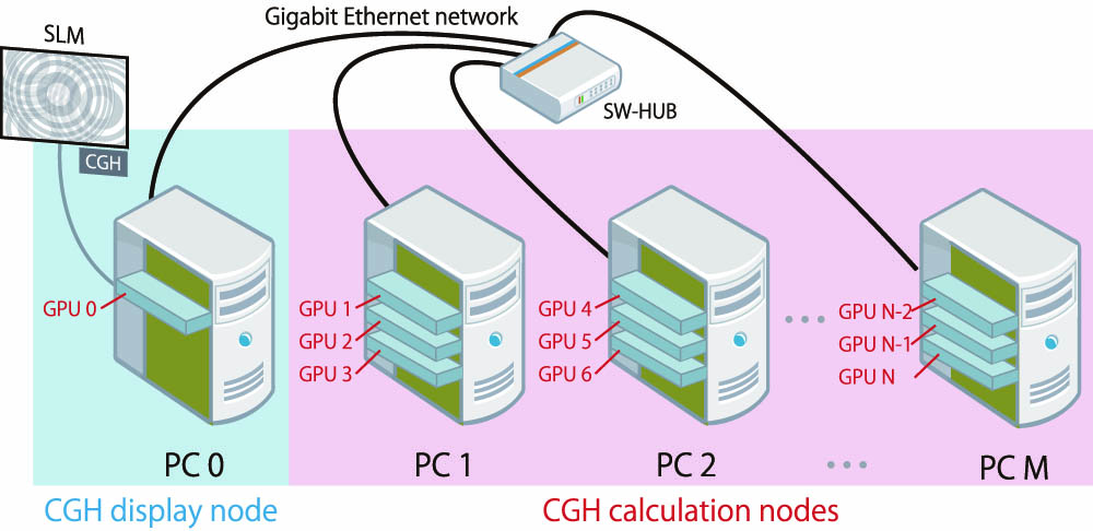
Figure 1 shows the proposed system, with a single SLM and a multi-GPU cluster connected by a gigabit Ethernet network. In the proposed system, the multi-GPU cluster consists of a CGH display node (PC 0) with a GPU and M CGH calculation nodes (PC 1 – PC M), each of which is equipped with three GPUs. Here we accommodate three GPUs in one PC because it can be readily extended to color electroholography, which has more practical usages. Thus, the multi-GPU cluster has GPUs. All nodes are connected by a gigabit Ethernet network. The CGH calculation nodes generate CGHs for all frames in a 3D video using pipeline processing. Each of the CGH calculation nodes sends the calculated CGH to the CGH display node, which displays the CGHs on an SLM in the frame order of the original 3D video. Furthermore, the coordinate data of the 3D object points for all frames in the original 3D video is stored in an auxiliary storage device of the CGH display node, which also plays the role of the network file server.
Figure 1.Proposed system with a single SLM and a multi-GPU cluster connected by gigabit Ethernet network.
Figure 2 shows a schematic outline of real-time electroholography using the proposed system, where Frame denotes the frame in the original 3D video. In the CGH calculation, each of the frames—from Frame 1 to Frame —is assigned to one of the GPUs—from GPU 1 to GPU —and each GPU calculates the CGH for the assigned frame. After each GPU finishes calculating the assigned CGH, the CGH calculation node containing that GPU sends the calculated CGH to the CGH display node. The CGH display node receives the calculated CGHs from Frame 1 to Frame in turn, and GPU 0 displays the respective CGHs in the frame order of the original 3D video on the SLM for a constant time .
Figure 2.Pipeline processing for real-time electroholography using the proposed system.
This process is repeated for successive groups of frames until the last frame of the original 3D video is reached. The GPUs from GPU 1 to GPU calculate all the CGHs using the pipeline processing shown in Fig. 2.
In the reconstructed 3D video, the CGH calculation for each frame is performed in the time . The process shown in Fig. 2 is implemented on a multi-GPU cluster in the proposed system (Fig. 1) using a message-passing interface.
In a previous study[18], the transferred data volume of a CGH image was , and the resolution of the CGH image was . Here a CGH image is expressed with 32 bits per pixel, so the method can be applied to phase-only and color CGHs as well as binary CGHs. The transfer time between the CGH display node and each CGH calculation node is 62.9 ms if a gigabit Ethernet is used for the network. To achieve real-time electroholography, the CGH must be displayed on the SLM at time intervals of 33.3 ms [30 frames per second (fps)]. The CGH transfer time between the CGH display node and each CGH calculation node is therefore a bottleneck. To overcome this bottleneck, we used an InfiniBand QDR (40 Gbps) as a high-speed network in a multi-GPU cluster to achieve real-time electroholography. With this high-speed cable, the theoretical transfer time between the CGH display node and each CGH calculation node is less than 2 ms.
In the present Letter, we overcome this bottleneck by reducing the volume of transferred data instead of using a high-speed network such as InfiniBand. First, a binary CGH image is created in black and white. The binary CGH can be expressed with 1 bit per pixel. However, in a general-purpose computer, the data is processed in units of bytes. Even a 1 bit binary value is thus stored as a variable with a data length of at least 1 byte (8 bits).
We can reduce the volume of transferred data by using a method for efficient storage of binary CGH data in 32 bit unsigned integer variables (hereinafter referred to as “packing”). The proposed packing process exploits the fact that a binary CGH is expressed as 1 bit per pixel, and the volume of transferred data is 1/32 of the data transfer in our previous study[18]. As shown in Fig. 2, the packing process is performed after each GPU in a CGH calculation node has calculated the light intensity in the CGH at each frame using Eq. (1). Figure 3 shows an outline of the packing process, which proceeds as follows. Step 1: Each GPU of each CGH calculation node calculates the light intensity in the CGH at the assigned frame using Eq. (1). Here, each calculated intensity is expressed as a 32 bit floating-point number. The calculated light intensities are then stored in the two-dimensional float array .Step 2: Each light intensity stored in the array is binarized with the threshold value of 0. The binarized light intensity is set to 1 when the light intensity is more than zero and is set to 0 otherwise.Step 3: Using bit shift, the binarized light intensity for each pixel in the binary CGH is stored bit-by-bit in the packed data , where is a one-dimensional, unsigned integer array. Thus, 32 bits of binarized light intensity can be stored in each element of the array , as shown in Fig. 3.
Figure 3.Outline of the packing process used to reduce the volume of data transferred.
In the multi-GPU cluster, each CGH calculation node calculates a binary CGH and sends the packed data to the CGH display node. The CGH display node produces binary CGH images by unpacking the packed data, and it displays the binary CGH image on the SLM. Figure 4 outlines the unpacking process, which uses the following steps. Step 1: The most significant bit (MSB) of the first element of the packed data array received from the CGH calculation node is referred. Here, MSB is the highest bit in a 32 bit binary number.Step 2: The corresponding pixel of the binary CGH is drawn in white when and is drawn in black otherwise.Step 3: The packed data is shifted 1 bit to the left.
Figure 4.Outline of the unpacking process used to reproduce the binary CGH.
This process is repeated until the entire binary CGH is produced.
We tested the performance of the proposed method with a prototype electroholography device. Figure 5 shows the display-time intervals obtained using a multi-GPU cluster connected by a gigabit Ethernet and the intervals obtained when using the multi-GPU cluster connected by InfiniBand QDR. The resolution of the test binary CGH image is , and the multi-GPU cluster consists of a CGH display node with a single GPU and four CGH calculation nodes. Each CGH calculation node has three GPUs. Table 1 lists the specifications of the PCs used in the test multi-GPU clusters. In Fig. 5, “Gigabit Ethernet (CPU)” shows the display-time intervals obtained using a multi-GPU cluster connected by a gigabit Ethernet when the packing and unpacking processes are performed by CPUs. “Gigabit Ethernet (GPU)” shows the display-time intervals obtained when using multi-GPU clusters connected by a gigabit Ethernet when the packing and unpacking processes are performed by GPUs. “InfiniBand” shows the display-time intervals obtained using multi-GPU clusters connected by InfiniBand QDR without the packing and unpacking processes[18]. The performance of the “Gigabit Ethernet (CPU)” system deteriorates when the number of object points is less than 61,440 points, compared with “InfiniBand.” The packing and unpacking processes by the CPU took, respectively, 7.22 ms and 6.61 ms, and they did not depend on the number of object points.
Figure 5.Comparison of a multi-GPU cluster connected with InfiniBand QDR and a multi-GPU cluster connected with a gigabit Ethernet.
To prevent this performance deterioration, we implemented packing and unpacking processes using GPUs. The corresponding time for the packing and unpacking processes using GPUs was reduced to 0.27 ms and 0.20 ms, respectively. These are approximately 30 times faster than those obtained using CPUs. By performing the packing and unpacking processes with GPUs, the multi-GPU cluster connected by a gigabit Ethernet returned a superior performance, equivalent to that of a multi-GPU cluster connected by InfiniBand QDR.
Furthermore, we evaluated the performances of two different multi-GPU clusters, shown in Tables 1 and 2. Figure 6 plots the display-time intervals achieved by these two multi-GPU cluster systems against the number of object points. The two multi-GPU clusters were each connected by a gigabit Ethernet, and they performed the packing and unpacking processes with a GPU to reduce the volume of data transfer. The multi-GPU cluster consisting of 13 NVIDIA GeForce GTX 1080 Ti boards performed twice as fast as that consisting of 13 NVIDIA GeForce GTX TITAN X boards. Figure 6 shows that the latter cluster can achieve real-time electroholography when the number of object points is less than 204,800. Figure 7 shows a snapshot of a reconstructed 3D video of the 3D point-cloud model “fountain,” comprised of 197,480 points. The 3D model was located 1.5 m from the CGH. The size of the 3D model is approximately . One of three transmissive liquid crystal display (LCD) panels, that were mounted on a projector (Epson Inc. EMP-TW1000), was used as the SLM. In the LCD panel, the resolution and the pixel pitch are and 8.5 μm, respectively. The green semi-conductor laser with a wavelength of 532 nm is used as the reconstructing light.
Item
Specification
CPU
Intel Core i7 7800X (Clock speed: 3.5 GHz)
Main memory
DDR4-2666 16 GB
OS
Linux (CentOS 7.6 x86_64)
Software
NVIDIA CUDA 10.1 SDK, OpenGL, MPICH 3.2
GPU
NVIDIA GeForce GTX 1080 Ti
Table 2. Specifications of the Multi-GPU Cluster Using NVIDIA GeForce GTX 1080 Ti
We have thus demonstrated successful real-time electroholography with the proposed multi-GPU cluster system connected with a gigabit Ethernet. The system was able to display a 3D video of the 3D point-cloud model of a fountain, consisting of 197,480 points, with the CGH calculation nodes using 12 GPUs (NVIDIA GeForce GTX 1080 Ti) in total.
In the proposed method, the volume of data transfer is reduced significantly using the binary CGH image. However, the image quality of the reconstructed 3D image from the binary CGH image is deteriorated compared with that from the grayscale CGH image. Thus, the tradeoff exists between an increased data transfer speed and a degrading image quality.
The proposed system with a single SLM is limited to a single color electroholography. In future, we plan to apply the proposed method to a color electroholography.
[21] S. Ikawa, N. Takada, H. Araki, H. Niwase, H. Sannomiya, H. Nakayama, M. Oikawa, Y. Mori, T. Kakue, T. Shimobaba, T. Ito. Chin. Opt. Lett., 18, 010901(2020).
Hiromi Sannomiya, Naoki Takada, Tomoya Sakaguchi, Hirotaka Nakayama, Minoru Oikawa, Yuichiro Mori, Takashi Kakue, Tomoyoshi Shimobaba, Tomoyoshi Ito. Real-time electroholography using a single spatial light modulator and a cluster of graphics-processing units connected by a gigabit Ethernet network[J]. Chinese Optics Letters, 2020, 18(2): 020902