
Fanlin MENG, Shi SU, Guoyu ZHANG, Jian ZHANG, Shi LIU, Gaofei SUN, Haowen PENG. Design Method of Solar Radiation Simulation Optical System with High Energy Utilization Rate[J]. Acta Photonica Sinica, 2021, 50(12): 1222003
- Acta Photonica Sinica
- Vol. 50, Issue 12, 1222003 (2021)
Abstract
Keywords
0 Introduction
Solar simulator is a kind of test equipment and calibration equipment that simulates solar radiation with artificial light source[
In order to realize the simulation of solar irradiation with large area spots, most of the large-scale solar simulators currently use off-axis optical system, and several xenon lamps are used as the array of light sources[
In addition, the current research on solar simulator is mostly focused on how to improve the irradiation uniformity, and there are few studies on how to improve the energy utilization rate. For example, PARUPUDIA R V and others designed parabolic mirrors to effectively improve the irradiation uniformity of the solar simulator[
In some fields, combined condenser systems are used to improve the energy utilization rate. For example, MENG Xiangxiang and others designed a trapezoidal secondary concentrator to improve the conversion efficiency of laser cells[
Aiming at the problems of high cost, complex structure, low energy utilization rate and poor irradiation uniformity of the current large-scale solar simulator, a solar radiation simulation optical system with high energy utilization rate is designed. The combined condenser system is adopted to improve the energy utilization rate and the edge compensation method is used to improve the irradiation uniformity. The simulation of solar irradiation with high energy utilization rate and high uniformity is realized.
1 General layout of a solar radiation simulation optical system with high energy utilization rate
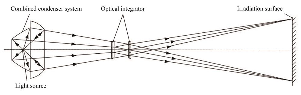
The solar radiation simulation optical system with high energy utilization rate consists of a high-power xenon lamp light source, a concentrating system and a homogenizing system, as shown in
![]()
Figure 1.Solar radiation simulation optical system
In order to improve the energy utilization rate, the concentrating system adopts the combined condenser system, which is composed of an ellipsoidal condenser and a spherical reflector. The homogenizing system uses the optical integrator to homogenize the convergent Gaussian radiation distribution and emit it at a certain divergence angle[
2 Optical system design
2.1 Combined condenser system design
2.1.1 Ellipsoid condenser design
In previous designs, the xenon lamp was ideally used as a point light source and a single ellipsoid condenser was used to collect the light. However, the real xenon light source obeys a certain luminous intensity and angular distribution, limited by the containment angle, there will be a large amount of stray light that cannot be used. In order to avoid the energy loss beyond the containment angle, eliminate stray light and improve the energy utilization rate, a combined condenser system composed of ellipsoid condenser and spherical reflector is adopted[
The xenon arc is simplified to a cylindrical model with length l0 and diameter d0. The light path principle of the ellipsoid condenser is shown in
![]()
Figure 2.The light path principle of the ellipsoid condenser
The x-axis is the optical axis, F1 is the first focus, F2 is the second focus, D1 is the rear opening diameter of the condenser, D is the front opening diameter of the condenser, D0 is the optical aperture of the optical integrator, angle u is the aperture angle of incident beam, angle u′ is the aperture angle of the outgoing beam, angle u0 is the rear opening aperture angle corresponding to the luminous point on the shaft, angle um is the front opening aperture angle corresponding to the luminous point on the shaft, angle ul is the aperture angle corresponding to the beam b emanating from the luminous point A(f1-l,0) on the axis, l is the distance from point A to point F1, beams a and c are the beams emitted from the rear opening and the front opening respectively.
Let the ellipsoid equation be
The range of the effective containment angle of the ellipsoid condenser should match the light distribution curve of the xenon lamp to maximize the energy utilization. The luminous range of the xenon lamp light distribution curve is 30°~135°. In order to make full use of the light energy, the reflection area of the ellipsoid condenser should contain this area. D1 is determined by u0, and D is determined by um. According to
After D is determined, the depth H of the ellipsoid condenser is calculated
In addition to the light emitted by the luminescent point at F1 converging to F2 for imaging, the light emitted by other luminescent points outside F1 at different incident angles is reflected, and the position on the second focal plane is a function of the incident Angle. Only the actual calculation of the light can determine the accurate position of the image point. If the light from A(f1-l,0) on the xenon arc axis intersects the ellipsoid at the point B(x0,y0), when the aperture Angle ul is given, the incident ray equation is,
B(x0,y0) can be obtained according to
where
When x=f2, the intersection of the light emitted by A(f1-l,0) with the second focal plane after being reflected by the ellipsoid can be calculated. When the light is incident at the aperture angle ulm, the y value of the intersection point with the second focal plane after reflection from the ellipsoid condenser is the maximum, so that the spot diameter at the second focal plane can be determined. In order to ensure a high energy utilization rate, the optical aperture D0 of the field lens set of the optical integrator is equal to the spot diameter at the second focal plane.
2.1.2 Spherical reflector design
In order to improve the energy utilization rate, the optical axes of the spherical reflector and the ellipsoid condenser coincide, and the light from the edge of the ellipsoid condenser can enter the spherical reflector, so that the light beyond the containment angle can be used for a second time. According to the optical principle of the sphere, the light emitted by the xenon lamp located at the center of the sphere is reflected by the spherical reflector, and the light will be reflected back to the center of the sphere without spherical aberration and loss. Using this principle, the center of the spherical reflector coincides with the first focus F1 of the ellipsoid condenser. The direct light emitted by the xenon lamp is reflected back to F1 through the spherical reflector, and then converged to F2 through the ellipsoid condenser, which reduces the energy loss and improves the energy utilization rate.
The external dimensions of the spherical reflector are shown in
![]()
Figure 3.The external dimensions of the spherical reflector
The spherical equation is
The diameter D2 of the back opening of the spherical mirror and the diameter D3 of the front opening are
where β=α, α is the aperture angle of the rear opening corresponding to F1, and θ is the aperture angle of the outgoing beam corresponding to the edge rays of the ellipsoid condenser.
2.2 Homogenizing system design
The homogenization system adopts an optical integrator to homogenize the Gaussian radiation distribution and emit it at a certain divergence angle. The optical integrator is composed of a field lens group LF, a projection lens group LP and two additional lenses (L1 and L2), as shown in
![]()
Figure 4.The structure of optical integrator
The field lens group and the projection lens group are composed of multiple element lenses arranged symmetrically according to the center. The aperture and focal length of the two groups of element lenses are the same, and they are in the focal plane of each other. If the number of element lenses is too small, the evenness effect cannot be guaranteed. In excess, the uniformity is affected by machining errors. Considering the processing difficulty and the effect of uniform light, 19 regular hexagonal element lenses are selected. The diameter of the inner circle of the element lens d is
where N is the number of element lenses contained in the diameter of the outer tangential circle of the optical integrator.
In order to improve energy utilization rate and reduce stray radiation of optical system, it is necessary to consider the factor that the relative aperture of the condenser system matches the relative aperture of the element lens of optical integrator. According to the principle of pupil matching, the following relation is established to calculate the focal length f of the element lens,
The whole optical integrator system is represented by six matrices, the first matrix is incident matrix, the next four are field mirror matrix, projection mirror matrix, and the last one is additional mirror matrix. The incident angle of the rays is u′, and the exit angle is u′′. The focal length of the two groups of element lenses is the same,
When the working distance l and divergence Angle α are given, the optical aperture
The irradiance at the edge of the irradiation surface of the solar simulator is usually lower than the central irradiance. The edge compensation method is usually adopted, that is, several small triangular lenses are added to the edge of the optical integrator to improve the edge irradiance, so as to improve the irradiation uniformity. However, considering the processing cost, an edge elimination aperture is designed according to the element lens array to intercept the edge light and ensure that the light can only pass through the element lens to improve the irradiation uniformity. Edge compensation method and edge elimination method are shown in
![]()
Figure 5.Edge compensation method
![]()
Figure 6.Edge elimination method
3 Simulation and experiment
3.1 Simulation analysis
The working distance of the solar radiation simulator optical system is 20 m, and the diameter of the irradiation surface is Φ2 m. The optical parameters are shown in
3.1.1 Comparison of energy utilization rate between single ellipsoid condenser and combined condenser system
A single ellipsoid condenser and a combined condenser system were modeled and simulated by using LightTools software. The receiver was placed at the second focal plane, and the radiation flux was set as 20 000 W. The energy utilization rate of the two was compared. The simulation light path is shown in
![]()
Figure 7.Simulation light path diagram
![]()
Figure 8.Energy utilization rate comparison
As can be seen from
3.1.2 Comparison of irradiation uniformity between uncompensated optical integrator, edge compensation method and edge elimination method
LightTools software was used to model and simulate the optical integrator, and the irradiation uniformity of uncompensated, edge compensation method and edge elimination method was compared. The simulation model is shown in
![]()
Figure 9.Simulation model of optical integrator
![]()
Figure 10.Comparison of irradiation uniformity
As can be seen from
3.1.3 Integrated optical system simulation
LightTools software was used to simulate the integrated optical system by combining the modeling of the combined condenser system and optical integrator. The simulation model is shown in
![]()
Figure 11.Optical system simulation model
![]()
Figure 12.Simulation results of irradiation uniformity
The calculation formula of irradiation non-uniformity is[
where ε is the irradiation non-uniformity, Emax is the maximum irradiance and Emin is the minimum irradiance.
As can be seen from
3.2 Experimental verification
The working distance and the diameter of the irradiation surface of the solar radiation simulator with high energy utilization rate were tested by using the laser anomaly calibration system. When the working distance is 20 m, the diameter of the irradiation surface is Φ2 m. The uniformity was measured and evaluated with FZ-A solar irradiance meter from Beijing Normal University Photoelectric Instrument Factory. The wavelength range of FZ-A solar irradiance meter is (400~1 000) nm, the minimum resolution is 10-4 mW·cm-2 and the upper limit of measurement is 199.9 mW·cm-2.
The short-arc xenon lamp was lit, and the FZ-A solar irradiance meter was placed on the effective working irradiation surface of the solar simulator, with the photosensitive surface facing the mirror cylinder of the solar simulator. After the light source was stabilized, 41 sampling points were selected on the effective irradiation surface to conduct the irradiation non-uniformity test, and repeated measurements were made for several times to eliminate the errors caused by light intensity instability. The distribution of test sampling points is shown in
![]()
Figure 13.Distribution of test sampling points
![]()
Figure 14.Test results of irradiation non-uniformity
Table Infomation Is Not EnableThe maximum irradiance and minimum irradiance in the effective irradiation surface measured by the experiment are 1 363.1 W·m-2 and 1 245.4 W·m-2 respectively. According to
4 Conclusion
A design method of solar radiation simulation optical system with high energy utilization rate using a single high power xenon lamp as light source was proposed. Based on the luminous characteristics of real xenon lamp, the ellipsoid condenser was designed. On this basis, the combined condenser system was used to improve the energy utilization rate by adding a spherical reflector. The optical integrator was designed according to the principle of pupil matching and the irradiation uniformity was improved by using the edge elimination method. The simulation results show that the energy utilization rate of the combined condenser system is increased by 21.2% compared with that of a single ellipsoid condenser. Compared with the edge compensation method, the irradiation uniformity is improved by 4% by using the edge elimination method of optical integrator. The experimental results show that the working distance is 20 m, the diameter of the irradiation surface is Φ2 m, the maximum irradiance is 1 363.1 W·m-2, and the irradiation non-uniformity is ±4.5%. It has broken the shortcomings of the large size, complex structure, low energy utilization rate and poor uniformity of the previous large-scale solar simulator, and provided an advanced means for the ground semi-physical simulation and testing of the solar sensor in the field of space.
References
[13] Tao LV, Donghui FU, Xiaoyun CHEN et al. Effect of optical intergrator element lenses' number and shape on the lighting uniformity of solar simulator. Journal of Optoelectronics·Laser, 25, 1849-1853(2014).
[15] Qibo GUO. A combined LED condenser lens.
[16] Chen YANG, Ruimin ZENG. A combined face body light gathering device.
[17] Qing WU, Songyue LIU, Chuande DU. High reflectivity light distribution bulb with elliptic and multi-curved combination concentrating light and a manufacturing method thereof.

Set citation alerts for the article
Please enter your email address
© Copyright 2018-2021 | Chinese Laser Press. All Rights Reserved 沪ICP备15018463号-20