• Laser & Optoelectronics Progress
  • Vol. 58, Issue 17, 1714008 (2021)
Xutian Chai1, Yan Yin1、*, Zhipeng Wang1, Kaiji Dong1, Zhihui Li1, and Ruihua Zhang2、3
Author Affiliations
  • 1State Key Laboratory of Advanced Processing and Recycling of Nonferrous Metals, Lanzhou University of Technology, Lanzhou , Gansu 730050, China
  • 2China Iron & Steel Research Institute Group, Beijing 100081, China
  • 3Hardware Knife Cut Industrial Technology Research Institute of Yangjiang, Yangjiang , Guangdong 529533, China
  • show less
    DOI: 10.3788/LOP202158.1714008 Cite this Article Set citation alerts
    Xutian Chai, Yan Yin, Zhipeng Wang, Kaiji Dong, Zhihui Li, Ruihua Zhang. Joint Microstructure and Properties of D36 Steel Using Narrow Gap Laser Welding[J]. Laser & Optoelectronics Progress, 2021, 58(17): 1714008 Copy Citation Text show less
    Schematic diagram of narrow gap laser filler wire welding
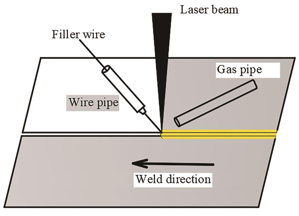
    Fig. 1. Schematic diagram of narrow gap laser filler wire welding
    Narrow gap welding groove
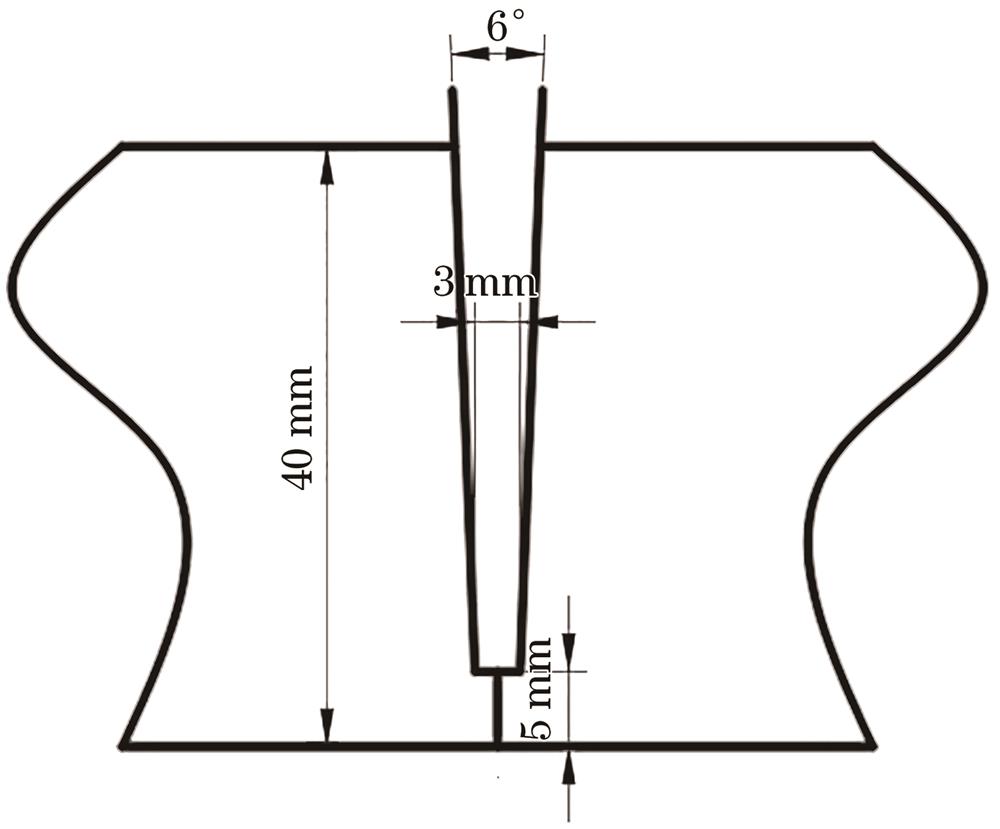
    Fig. 2. Narrow gap welding groove
    Sampling of macroscopic cross-section and micro-hardness of weld
    Fig. 3. Sampling of macroscopic cross-section and micro-hardness of weld
    Structure distribution of each zone of welded joint
    Fig. 4. Structure distribution of each zone of welded joint
    Microstructure of base metal
    Fig. 5. Microstructure of base metal
    Microstructures of weld center. (a) Low magnification ; (b) high magnification
    Fig. 6. Microstructures of weld center. (a) Low magnification ; (b) high magnification
    Microstructures of HAZs. (a) CGHAZ; (b) FGHAZ; (c) INZ
    Fig. 7. Microstructures of HAZs. (a) CGHAZ; (b) FGHAZ; (c) INZ
    Overlapping microstructures in weld zone. (a) Low magnification overlapping microstructure; (b) high magnification overlapping microstructure
    Fig. 8. Overlapping microstructures in weld zone. (a) Low magnification overlapping microstructure; (b) high magnification overlapping microstructure
    Overlapping microstructures in heat affected zone. (a) Low magnification overlapping microstructure; (b) high magnification overlapping microstructure
    Fig. 9. Overlapping microstructures in heat affected zone. (a) Low magnification overlapping microstructure; (b) high magnification overlapping microstructure
    Microhardness of different areas of weld
    Fig. 10. Microhardness of different areas of weld
    Tensile fracture of welded joint
    Fig. 11. Tensile fracture of welded joint
    Stress-strain curves of tensile sample
    Fig. 12. Stress-strain curves of tensile sample
    Tensile fracture morphologies. (a) Macro morphology; (b) micro morphology
    Fig. 13. Tensile fracture morphologies. (a) Macro morphology; (b) micro morphology
    ElementCMnSiNiPSCuCr
    Mass fraction≤ 0.1800.900‒1.600≤ 0.500≤ 0.400≤ 0.035≤ 0.035≤ 0.350≤ 0.200
    Table 1. Chemical compositions of D36 steel with high strength (mass fraction)
    ElementCMnSiPSCrCu
    Mass fraction≤ 0.1501.400‒1.8500.800‒1.150≤ 0.025≤ 0.035≤ 0.500≤ 0.200
    Table 2. Chemical compositions of ER50-6 filler wire (mass fraction)
    Sampling locationYield strength /MPaTensile strength /MPaElongation /%Fracture position
    BM31249634.6BM
    Upper37652517.2BM
    Middle37053315.0BM
    Bottom40255014.6BM
    Table 3. Results of tensile test
    Xutian Chai, Yan Yin, Zhipeng Wang, Kaiji Dong, Zhihui Li, Ruihua Zhang. Joint Microstructure and Properties of D36 Steel Using Narrow Gap Laser Welding[J]. Laser & Optoelectronics Progress, 2021, 58(17): 1714008
    Download Citation