• Advanced Photonics
  • Vol. 1, Issue 1, 016005 (2019)
Xingyuan Lu1, Yifeng Shao2, Chengliang Zhao1、2、*, Sander Konijnenberg2, Xinlei Zhu1, Ying Tang2, Yangjian Cai1、3, and H. Paul Urbach2
Author Affiliations
  • 1Soochow University, School of Physical Science and Technology, Suzhou, China
  • 2Delft University of Technology, Optics Research Group, Delft, Netherlands
  • 3Shandong Normal University, School of Physics and Electronics, Center of Light Manipulation and Application, Jinan, China
  • show less
    DOI: 10.1117/1.AP.1.1.016005 Cite this Article Set citation alerts
    Xingyuan Lu, Yifeng Shao, Chengliang Zhao, Sander Konijnenberg, Xinlei Zhu, Ying Tang, Yangjian Cai, H. Paul Urbach. Noniterative spatially partially coherent diffractive imaging using pinhole array mask[J]. Advanced Photonics, 2019, 1(1): 016005 Copy Citation Text show less
    Schematic plot of the experimental setup and the concept of the noniterative diffractive imaging method. (a) A PAM is placed between the object and the camera. The PAM is specially designed such that we can retrieve the correlation function of the incident light by inverse Fourier transform of the measured diffraction pattern. (b) The PAM consists of a reference pinhole at the origin (gray square) and a periodic array of the measurement pinholes with certain offset (white squares). (c) In the inverse Fourier transform of the diffraction pattern, the autocorrelation terms (gray squares) and the two interference terms (red and blue squares) are separated by the offset. Each interference term directly contains the correlation between the fields at the reference pinhole and at the measurement pinholes.
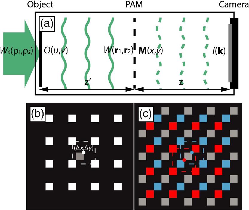
    Fig. 1. Schematic plot of the experimental setup and the concept of the noniterative diffractive imaging method. (a) A PAM is placed between the object and the camera. The PAM is specially designed such that we can retrieve the correlation function of the incident light by inverse Fourier transform of the measured diffraction pattern. (b) The PAM consists of a reference pinhole at the origin (gray square) and a periodic array of the measurement pinholes with certain offset (white squares). (c) In the inverse Fourier transform of the diffraction pattern, the autocorrelation terms (gray squares) and the two interference terms (red and blue squares) are separated by the offset. Each interference term directly contains the correlation between the fields at the reference pinhole and at the measurement pinholes.
    The experimental setup for generating the GSM beam and for diffractive imaging. BE, beam expander; RGGD, rotating ground-glass disk; GAF, Gaussian amplitude filter; BS, beam splitter; SLM, spatial light modulator; PAM, pinhole array mask; L1, L2, and L3, thin lenses; and CCD, charge-coupled device.
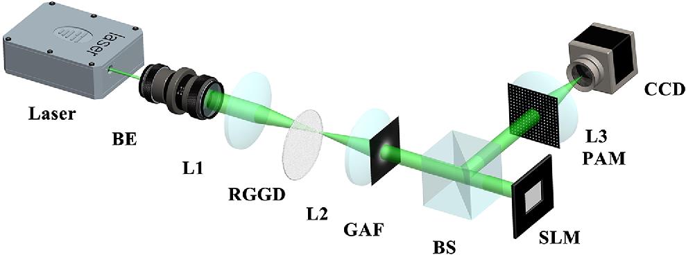
    Fig. 2. The experimental setup for generating the GSM beam and for diffractive imaging. BE, beam expander; RGGD, rotating ground-glass disk; GAF, Gaussian amplitude filter; BS, beam splitter; SLM, spatial light modulator; PAM, pinhole array mask; L1, L2, and L3, thin lenses; and CCD, charge-coupled device.
    The unperturbed and the perturbed object transmission function and the experimental results using GSM beam illumination with various degrees of spatial coherence. The phase of (a) the unperturbed and (b) the perturbed objects. The perturbation is at the head of the panda. (c1)–(c3) The amplitude and (d1)–(d3) the phase of the reconstructed product of the object’s transmission and the illumination’s correlation using GSM beam for illumination with various degrees of spatial coherence.
    Fig. 3. The unperturbed and the perturbed object transmission function and the experimental results using GSM beam illumination with various degrees of spatial coherence. The phase of (a) the unperturbed and (b) the perturbed objects. The perturbation is at the head of the panda. (c1)–(c3) The amplitude and (d1)–(d3) the phase of the reconstructed product of the object’s transmission and the illumination’s correlation using GSM beam for illumination with various degrees of spatial coherence.
    The experimental results under GSM beam illumination with low degree of spatial coherence (σ=0.21 mm) using the perturbation point at different locations of the object. (a)–(f) The experimental reconstruction results with the perturbation point at different locations. Each result shows a reduced FoV in the vicinity of the location of the perturbation point. (g) The combination of the results in (a)–(f), which shows a clear panda in the whole FoV.
    Fig. 4. The experimental results under GSM beam illumination with low degree of spatial coherence (σ=0.21  mm) using the perturbation point at different locations of the object. (a)–(f) The experimental reconstruction results with the perturbation point at different locations. Each result shows a reduced FoV in the vicinity of the location of the perturbation point. (g) The combination of the results in (a)–(f), which shows a clear panda in the whole FoV.
    The experimental results using LGSM beam illumination: (a) the reconstructed product of the object’s transmission and the illumination’s correlation; (b) the calibration results of the illumination’s correlation using an empty window as object; and (c) the object’s transmission obtained by dividing the results in (a) by the results in (b).
    Fig. 5. The experimental results using LGSM beam illumination: (a) the reconstructed product of the object’s transmission and the illumination’s correlation; (b) the calibration results of the illumination’s correlation using an empty window as object; and (c) the object’s transmission obtained by dividing the results in (a) by the results in (b).
    Xingyuan Lu, Yifeng Shao, Chengliang Zhao, Sander Konijnenberg, Xinlei Zhu, Ying Tang, Yangjian Cai, H. Paul Urbach. Noniterative spatially partially coherent diffractive imaging using pinhole array mask[J]. Advanced Photonics, 2019, 1(1): 016005
    Download Citation