
C. Emma, J. Van Tilborg, R. Assmann, S. Barber, A. Cianchi, S. Corde, M. E. Couprie, R. D’Arcy, M. Ferrario, A. F. Habib, B. Hidding, M. J. Hogan, C. B. Schroeder, A. Marinelli, M. Labat, R. Li, J. Liu, A. Loulergue, J. Osterhoff, A. R. Maier, B. W. J. McNeil, W. Wang. Free electron lasers driven by plasma accelerators: status and near-term prospects[J]. High Power Laser Science and Engineering, 2021, 9(4): 04000e57
- High Power Laser Science and Engineering
- Vol. 9, Issue 4, 04000e57 (2021)
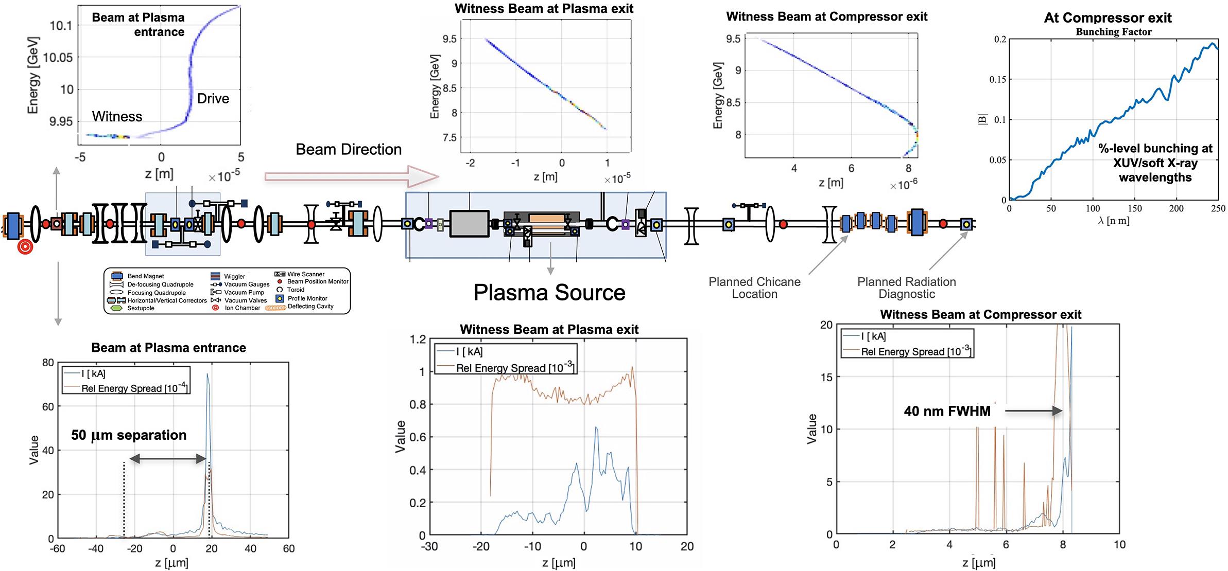
Fig. 1. Schematic of the FACET-II experimental area with the planned location of an additional small chicane and radiation diagnostic to be used for X-FEL experiments. The simulated longitudinal phase space evolution shows the compression of the electron beam to attosecond duration with percent-level bunching at XUV/soft X-ray wavelengths.
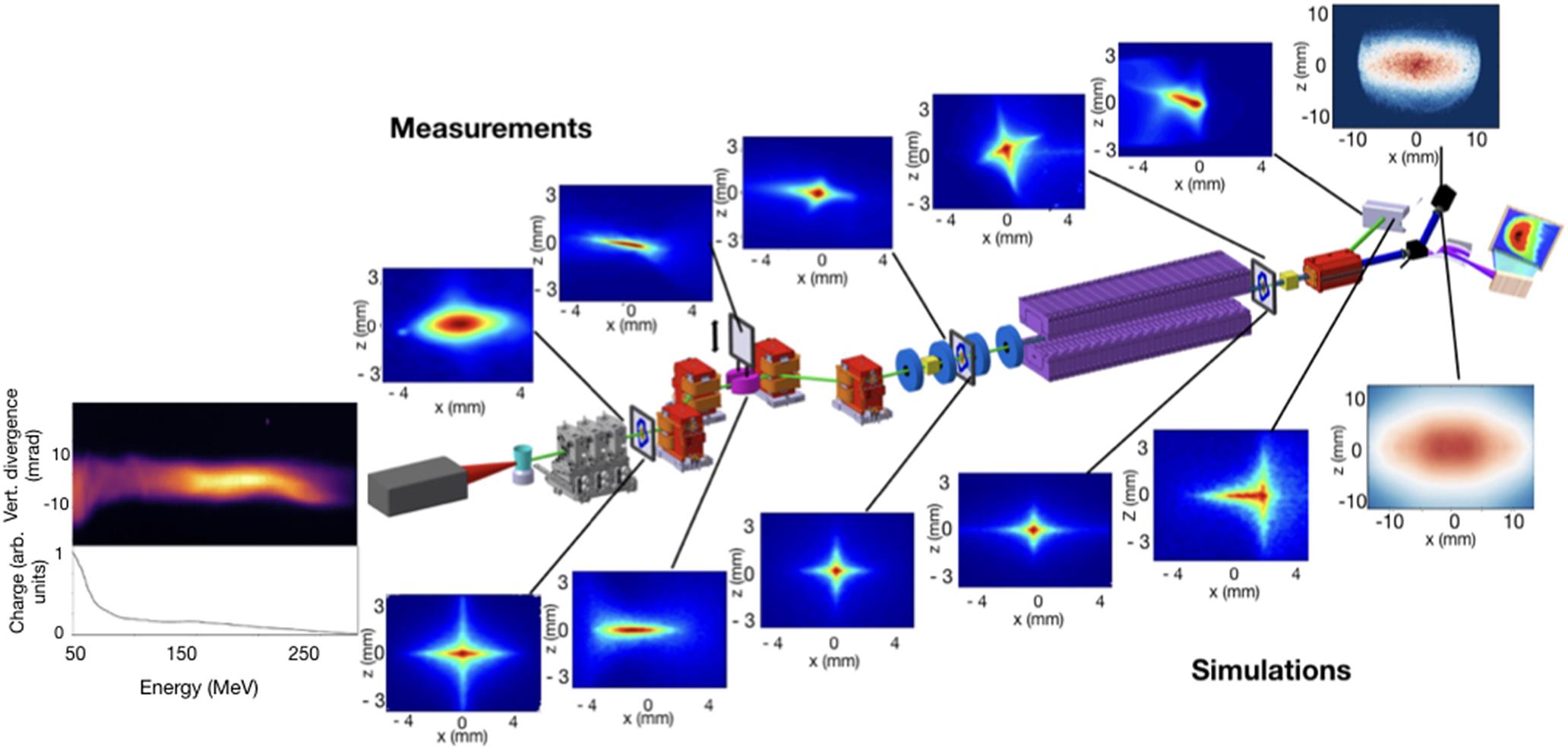
Fig. 2. COXINEL electron and photon beam measurements compared to simulations. Left: Electron beam spectrometer measurements and transverse distributions along the screens (top: measurements; bottom: simulations using the measured electron beam distribution as an input). Right: Undulator radiation transverse pattern (measured with a CCD camera and modeled using the transported electron beam without electron energy selection).
Fig. 3. Average power as a function of the number of drive bunches per second at a range of existing or planned plasma-wakefield research facilities (bottom left corner) and photon-science and high-energy-physics user facilities (top right). The blue arrow represents the leap towards a beam-driven plasma-based FEL by using high-average-power upgrades to FLASHForward as a gateway.
Fig. 4. Schematic view of the LUX beamline after upgrade. For simplicity, diagnostics, such as electron beam profile monitors, are not shown.
Fig. 5. The SIOM-FEL setup with planar undulators and transverse gradient undulators.
Fig. 6. Plasma-based X-FEL and other ultrabright light sources options as summarized in the UK X-FEL science case[81].
Fig. 7. Schematic layout of the BELLA Center’s Laser-Plasma Accelerator FEL beamline. The inset shows the electron beam beta function (beam size squared) inside the undulator in (left) the optimally matched strong-focusing undulator, (middle) a mismatched strong-focusing undulator, and (right) an optimized natural-focusing undulator. The strong-focusing undulator allows for higher beam density over the full undulator length.
Fig. 8. Layout of the EuPRAXIA@SPARC LAB infrastructure.
LAB infrastructure.
|
Table 1. Summary of parameters for the facilities discussed in the text utilizing a laser-driven approach to plasma-FEL operation.
|
Table 2. Summary of parameters for the facilities discussed in the text utilizing a beam-driven approach to plasma-FEL operation. We note that both Strathclyde and EuPRAXIA are also aiming to study multiple plasma-based FEL approaches including hybrid LWFA–PWFA configurations. Facilities/groups labeled with an asterisk have not yet begun experimental operation and for those the target parameters have been listed.

Set citation alerts for the article
Please enter your email address
© Copyright 2018-2021 | Chinese Laser Press. All Rights Reserved 沪ICP备15018463号-20