
Jiexi Zuo, Haijuan Yu, Shuzhen Zou, Zhiyong Dong, Chaojian He, Shuang Xu, Chaoyu Ning, Xuechun Chen, Xinyao Li, Xuechun Lin. 1.2 kW all-fiber narrow-linewidth picosecond MOPA system[J]. High Power Laser Science and Engineering, 2023, 11(2): 02000e22
- High Power Laser Science and Engineering
- Vol. 11, Issue 2, 02000e22 (2023)
Abstract
1 Introduction
Due to the geometric characteristics of the gain medium, capillary fiber lasers and bulk solid-state lasers have the advantages of high power[1] and significant pulse energy[2], respectively. Driven by the robustness and cost-effectiveness of fiber systems, achieving an ultra-fast fiber system with approximately kW power and approximately mJ pulse energy comparable to the disk and slab schemes[3,4] is still an ambitious aim for researchers. During this mighty journey, adopting large mode area (LMA) photonic crystal fiber (PCF) and chirped pulse amplification (CPA) technology[5,6] has become the mainstream route to circumvent the obstacles of nonlinear effects in the power-scaling process. However, the current state-of-the-art fiber ultra-fast systems[7–9] contain the necessary precisely placed spatial optical components, such as dispersion management systems, rigid rod PCF amplifiers and phase stabilization systems, which weaken the advantageous properties of the fiber system. Due to the excessive cost and incredible complexity, the application scope of these systems is limited to scientific research scenarios.
Besides the scientific research demands for fs pulses, a monolithic, all-fiber, energy-efficient and CPA-free ps fiber source has considerable benefits for industrial applications: fast micro-machining[10], high-resolution lidar[11], combustion diagnostics[12], etc. A kilowatt-scale ps system with tens of μJ energy at MHz repetition frequency may achieve a compromise between the harsh thermal effects of continuous wave lasers and the low processing speed of fs lasers[13,14]. Moreover, a high-power infrared ps laser is the ideal pump source of second harmonic generation for the urgently needed visible pulse[15]. Meanwhile, a ps source with narrow spectral widths can mitigate the temporal walk-off effect during the harmonic conversion process[16] and enable a high spectral resolution in nonlinear micro-spectroscopic imaging applications, such as coherent anti-Stokes Raman scattering spectroscopy[17,18]. Furthermore, combined with nonlinear compression techniques, this efficient ps system can effectively scale the average power of fs lasers to the kW level[19,20].
In this contribution, a master oscillator power amplifier (MOPA) system composed of a passive mode-locked ps seed and four cascade fiber amplifiers was realized in an all-fiber manner. The nonlinear effects of this monolithic fiber system were suppressed by adopting a narrow-linewidth dispersion stretched seed pulse (~62.3 ps) and a multi-mode power amplifier with a core diameter of 100 μm. The final average output power exceeded 1.2 kW with a pulse energy over 48 μJ, the ultimate pulse was broadened to 107 ps, corresponding to a peak power of approximately 0.45 MW, and a narrow linewidth of 1.32 nm has been preserved. Moreover, the transverse mode instability (TMI) of this highly multi-mode fiber amplifier has been evaluated for the first time: although the beam propagation product has been degraded to 5.28 mm
Sign up for High Power Laser Science and Engineering TOC. Get the latest issue of High Power Laser Science and Engineering delivered right to you!Sign up now
2 Working principle
2.1 System design strategies
By adopting a rod-type PCF power amplifier, a fiber MOPA system has already achieved an ultra-fast pulse with mJ-level energy[21]. However, as a low splice loss for LMA-PCF is still insurmountable due to the collapsing of air holes during the fusing process, an inefficient spatially coupled pump structure was always necessary, and the final average power was limited to the hundred-watt level due to the transversal spatial hole burning effects[22,23]. In order to realize an entire all-fiber system by implementing standard fusion splicing processes, we replaced the PCF with a type of commercial solid fiber with an extra-large mode area (XLMA). Drawing on the idea of the pulse stretching process in the CPA scheme, a fiber Bragg grating (FBG) with picometer bandwidth was employed to induce a seed signal pulse with tens of ps[24], and the narrowband property can also avoid the gain-narrow effects of traditional CPA amplifiers. Meanwhile, a semiconductor saturable absorber was employed as the starter of the mode-locking, which has more substantial stability and self-starting advantages compared with artificial saturable absorbers[25]. In this way, a compact CPA-free linear-mode-locked seed cavity was constructed using semiconductor saturable absorber mirrors (SESAMs) and an FBG as the resonator mirrors. Moreover, the sequent cascade amplifiers have been constructed robustly, and we also demonstrated that the whole MOPA system exhibits good nonlinear tolerance ability and has the scaling feasibility of even higher peak power and pulse energy.
3 Experimental setup and results
3.1 Specifications of the signal pulses before the booster amplifier
The experimental setup of the MOPA system is shown in Figure 1. The seed cavity was confined between a SESAM and an output FBG coupler (with a reflectivity of 25%), and both central wavelengths were at 1064 nm. A 4 m cavity length provided the oscillator repetition rate of 25 MHz. Except for the gain fiber, all the passive fiber and the device pigtail in the cavity are non-polarization maintaining single-mode (SM) Corning HI1060 fiber. The 3 dB bandwidth of 70 picometers of the FBG was adopted to induce large group delay dispersion and protected the SESAM from damage by significant saturation[24,26]. An SM 976 nm laser diode was used via a 980/1060 wavelength division multiplexer (WDM). With 52 mW pump power injected into a 6-μm-core, 0.11-numerical aperture (NA), 30-cm-long single-mode ytterbium-doped fiber (SM-YDF, Nufern SM-YSF-HI-HP), a 12-mW stable self-starting mode-locked pulse train was generated, and the performance parameters were measured after the polarization insensitive fiber isolator (ISO1). The pulse train was monitored with a 5 GHz photodetector (Thorlabs-DET08CL) and a 1 GHz bandwidth sampling oscilloscope (Agilent Technologies DS07104B). Besides, the accurate pulse duration and spectrum are monitored by a commercial autocorrelator (APE SM-2000) and a spectrometer (AQ6370D with a resolution of 0.02 nm) here and in the following experiments.
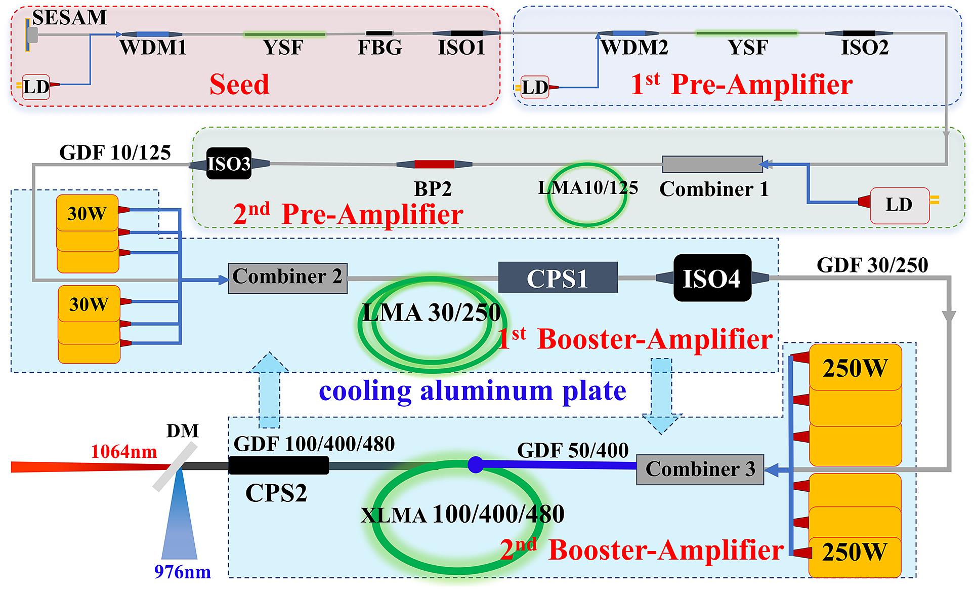
Figure 1.The general layout of the MOPA system: SESAM, semiconductor saturable absorber mirror; LD, laser diode at 976 nm; WDM, 980/1060 wavelength division multiplexer; YSF, ytterbium-doped single-mode fiber; FBG, fiber Bragg grating; ISO, isolator; BP, bandpass filter; LMA, large mode-field area; CPS, cladding pump stripper; XLMA, extra-large mode area; DM, dichroic mirror.
The specifications of the seed pulses are measured and shown in Figures 2(a) and 2(b), where the shape of the autocorrelation trace is a pedestal-free near-perfect hyperbolic secant profile. The measured full width at half maximum (FWHM) pulse width was 96 ps, corresponding to a deconvolution pulse width of 62.3 ps[27]. The spectral 3 dB bandwidth is 0.052 nm with a calculated time-bandwidth product of 0.858.
![]()
Figure 2.Measurement results of the seed: (a) spectral width in the logarithmic scale (with a resolution of 0.02 nm); (inset) snapshot of pulse train; (b) trace of intensity autocorrelation; (c) spectrum of pre-amplified signal: after and (inset) before the BPF2.
The seed pulse was coupled in two cascade pre-amplification stages denoted as the first pre-amplifier and the second pre-amplifier, respectively, in Figure 1. A 50 cm long SM-YDF (Nufern SM-YSF-HI-HP) and a 3 m LMA double-cladding fiber (Nufern-LMA-10/125-9M) were forward pumped through a WDM and a (2+1)
3.2 Nonlinear effects and efficiency of the booster amplifiers
The pre-amplified signal was coupled into the first booster amplifier through a forward pump/signal combiner, which had six multi-mode pump ports with core/cladding diameters of 105/125 μm and a core NA of 0.22. Each pump port was spliced with a 15 W fiber pigtailed laser diode module, of which the center wavelength was stabilized at 976 nm. The gain fiber was a 3-m LMA-YDF 30/250 μm double-cladding fiber, with a cladding pump absorption coefficient of 6.3 dB/m near 975 nm. A commercial cladding pump stripper was attached to the gain fiber tail end, and the output performance was monitored after the high-power isolator (ISO4 in Figure 1). As the pumping current increased, the output power increased linearly to more than 70 W, and the pump conversion efficiency was greater than 83% for the available pump. During this process, the measured signal spectra show typical self-phase modulation (SPM) evolution characteristics in Figure 3(a): the spectrum consists of several symmetric distributed oscillatory peaks, and the outermost peaks are the most intense.
![]()
Figure 3.(a) Experimentally observed spectral evolution with different pumping currents; (b) typical spectral evolution of an unchirped pulse under SPM; (c) signal bandwidth of seed and after amplification; (d) autocorrelation trace of the ultimate pulse.
Moreover, due to the linear up-chirp near the spectral center induced by the narrowband FBG[24], the spectral oscillation modulated by the subsequent SPM is not as drastic as a typical unchirped pulse, which is illustrated in Figure 3(b). Intuitively, this chirp characteristic is beneficial for maintaining the spectral purity of the narrow-linewidth pulse amplification process, resulting in a more concentrated power spectrum. However, further study is needed for an optimized reasonable chirp distribution to achieve better spectrum maintenance. After the final power amplification, the spectral bandwidth was subsequently broadened to 1.32 nm with a clear outline, as shown in Figure 3(c), and the ultimate pulse duration was 107.8 ps, which was deconvoluted from a near-sech2 autocorrelation trace in Figure 3(d).
Interestingly, the signal spectrum at the peak powers always exhibited a stable symmetric SPM expansion characteristic before the XLMA stage (see Figures 3(a) and 3(b), for example). However, the measured spectrum became no longer stable and unusually asymmetric after the XLMA fiber (Figure 3(c)). It is worth remembering that this was not the result of the intrinsic evolution mechanism, but rather was caused by the coupling filtering effect of the spectrometry process, which could be explained as the mode-beating effect[29] between the multi-mode output light source and the single-mode coupling jumper. Overall, lasers coming out from the fiber-end with different angles and positions will carry different spectral content. Then, the experimentally measured spectra will vary with the position setting of the laser source and fiber-jumper detector. An integrating sphere has been used to eliminate this spatial dependence due to the multiple diffuse reflections that occur on the inner wall of the integrating sphere, and the actual symmetric spectrum results with a low resolution were obtained too. In short, the spectral width under the two measurement schemes was consistent, which confirmed the validity of the results.
Furthermore, it is even more meaningful that the amplified symmetric spectrum indicating that the nonlinear phase was only introduced by the SPM and the interaction of other effects (high-order dispersion, intraband Raman effect and cross-phase modulation, for example) can be ignored. In this case, the accumulated frequency-chirp remained almost linear in the central region of the pulse. An additional diffraction grating compressor can be introduced to achieve an efficient dechirped pulse with a pulse duration below 10 ps[30]. Moreover, we estimated a total nonlinear phase-shift of 28.4 radians, whilst the seed spectral width broadened by approximately 25.4 times from its original value[31,32]. All of these manifested the strong nonlinear tolerance of the system.
To maintain the simplicity of fiber splicing and the flexibility of the amplifier, the pigtails of the high-power fiber components (Combiner2, CPS1, ISO4, Combiner3, CPS2) employed in the booster amplifiers have not been drastically cut back. For such a long-range multistage high-power system, the growth of SRS during the master amplifier was rapid and required more attention. With the increasing pump current of the first booster amplifier, a red-shifted Raman peak with a typical Raman gain profile for silica was observed[33]. The specific SRS content could be assessed by calculating the integral area of the Raman peak from 1090 to 1150 nm (shown in red in the inset of Figure 4(a)) among the spectral curves. The variation of the calculated Raman content with the pump intensity is shown in Figure 4(a): when the pump current exceeds a certain intensity, the output Raman content will increase exponentially, leading to rapid degradation of the high-power optical SNR. Without additional Raman suppression measures, the pump strength should be limited before exponential degradation occurs. On the other hand, insufficient signal power will lead to a lethal reverse ASE during the forward-pumped second booster amplifiers with high pump powers. Under careful consideration, we adopted a compromise pump current of 6 A, corresponding to a coupled pump power of 61.1 W, and the calculated percentage of first-order Raman content was 0.06%. At this point, the 1 W pre-amplified signal was boosted to 36.5 W with a signal ratio of Raman content of more than 32 dB.
![]()
Figure 4.(a) Raman content versus pump current of the first booster amplifier; (inset) global spectrum under 6 A pump measured at ISO4; (b) output power versus pump of the second booster amplifier; (c) spectrum at 1220 W output measured at the end of the XLMA.
At the last booster amplifier, a triple cladding YDF[34] with an XLMA and high cladding absorption was employed, enabling a short gain fiber length and low nonlinear effect. The diameter/NA of the core, first cladding, second cladding and coating diameter are 100 μm/0.11, 400 μm/0.22, 480 μm/0.46 and 630 μm, respectively. This fiber had a cladding absorption of 7.5 dB/m at 915 nm corresponding to an estimated total pump absorption of 22.5 dB at 976 nm in the 1 m long fiber. The pump source was six wavelength-locked 976 nm pump modules with a maximum power of 250 W coupled through a 200/220 pigtail fiber. Meanwhile, a customized (6+1)
Experimentally, the output power scaled linearly with increasing pump power, and no sign of rollover appeared until the maximum value. The maximal output power of over 1220 W was achieved under a pump power of 1465 W, corresponding to the slope efficiency of 81.3% in Figure 4(b). Meanwhile, the global spectrum result is shown in Figure 4(c): the SNRs of the signal were 47, 35.4 and 25.5 dB compared with the noise floor, ASE and first-order Raman peak, respectively. In addition, the calculated percentage of first-order Raman content was boosted from 0.06% to 1.17%, indicating that the Raman power underwent a lower gain than the signal, and most of the optical power remained at the signal wavelength with practical efficiency.
3.3 Output stability of the system
Admittedly, the power performance of this all-fiber system benefited from the LMA of the booster amplifier, and an expected degenerated beam quality of about 5.28 mm
![]()
Figure 5.Output stability of the system. (a) With a full collimated beam captured by a charge-coupled device (CCD); (inset) sampling spot selected by pinhole; (b) Fourier transform of the temporal trace; (c) power stability within 1 hour.
4 Conclusion and outlooks
In summary, we experimentally demonstrated a monolithic all-fiberized ps MOPA system with a high average power of 1.2 kW, a CPA-free peak power of 0.45 MW (~48 μJ/~107 ps) and a bandwidth of 1.32 nm. Further output power scaling is only limited by the SRS and the available pumps, as no roll-off in the signal power was observed during the booster amplification. By employing a Raman filter (e.g., tilted FBG[40]) and an additional reverse pumping module, multi-kW average power and multi-MW peak power will be realizable. In addition, the linear-chirp property of the ultimate output spectrum indicated a direct-compression advantage of the system
References
[1] J. W. Dawson, M. J. Messerly, R. J. Beach, M. Y. Shverdin, E. A. Stappaerts, A. K. Sridharan, P. H. Pax, J. E. Heebner, C. W. Siders, C. P. J. Barty. Opt. Express, 16, 13240(2008).
[2] C. N. Danson, C. Haefner, J. Bromage, T. Butcher, J. C. F. Chanteloup, E. A. Chowdhury, A. Galvanauskas, L. A. Gizzi, J. Hein, D. I. Hillier, N. W. Hopps, Y. Kato, E. A. Khazanov, R. Kodama, G. Korn, R. X. Li, Y. T. Li, J. Limpert, J. G. Ma, C. H. Nam, D. Neely, D. Papadopoulos, R. R. Penman, L. J. Qian, J. J. Rocca, A. A. Shaykin, C. W. Siders, C. Spindloe, S. Szatmari, R. M. G. M. Trines, J. Q. Zhu, P. Zhu, J. D. Zuegel. High Power Laser Sci, 7, e54(2019).
[3] P. Russbueldt, T. Mans, J. Weitenberg, H. D. Hoffmann, R. Poprawe. Opt. Lett., 35, 4169(2010).
[4] Y. Wang, H. Chi, C. Baumgarten, K. Dehne, A. R. Meadows, A. Davenport, G. Murray, B. A. Reagan, C. S. Menoni, J. J. Rocca. Opt. Lett., 45, 6615(2020).
[5] J. Limpert, F. Roser, T. Schreiber, A. Tunnermann. IEEE J. Sel. Top. Quantum Electron., 12, 233(2006).
[6] J. Zuo, X. Lin. Laser Photonics Rev., 16, 2100741(2022).
[7] A. Klenke, M. Müller, H. Stark, M. Kienel, C. Jauregui, A. Tünnermann, J. Limpert. IEEE J. Sel. Top. Quantum Electron., 24, 0902709(2018).
[8] M. Müller, C. Aleshire, A. Klenke, E. Haddad, F. Légaré, A. Tünnermann, J. Limpert. Opt. Lett., 45, 3083(2020).
[9] H. Stark, J. Buldt, M. Müller, A. Klenke, A. Tünnermann, J. Limpert. Opt. Lett., 44, 5529(2019).
[10] A. Nebel, T. Herrmann, B. Henrich, R. Knappe. , , , and , Proc. SPIE , 87 ().(2005).
[11] S. P. Narasimha, R. M. Anand. and , Proc. SPIE , 112870J ().(2020).
[12] E. Malmqvist, M. Brydegaard, M. Aldén, J. Bood. Opt. Express, 26, 14842(2018).
[13] S. Ravi-Kumar, B. Lies, X. Zhang, H. Lyu, H. Qin. Polym. Int., 68, 1391(2019).
[14] G. Zhu, D. Whitehead, W. Perrie, O. J. Allegre, V. Olle, Q. Li, Y. Tang, K. Dawson, Y. Jin, S. P. Edwardson, L. Li, G. Dearden. J. Phys. D: Appl. Phys., 51, 095603(2018).
[15] N. Ma, M. Chen, C. Yang, S. Lu, X. Zhang, X. Du. High Power Laser Sci., 8, e1(2020).
[16] Z. Zhao, B. Sheehy, M. Minty. Opt. Express, 25, 8138(2017).
[17] M. Chemnitz, M. Baumgartl, T. Meyer, C. Jauregui, B. Dietzek, J. Popp, J. Limpert, A. Tünnermann. Opt. Express, 20, 26583(2012).
[18] M. Baumgartl, M. Chemnitz, C. Jauregui, T. Meyer, B. Dietzek, J. Popp, J. Limpert, A. Tünnermann. Opt. Express, 20, 4484(2012).
[19] J. Schulte, T. Sartorius, J. Weitenberg, A. Vernaleken, P. Russbueldt. Opt. Lett., 41, 4511(2016).
[20] P. Balla, A. Bin Wahid, I. Sytcevich, C. Guo, A.-L. Viotti, L. Silletti, A. Cartella, S. Alisauskas, H. Tavakol, U. Grosse-Wortmann, A. Schönberg, M. Seidel, A. Trabattoni, B. Manschwetus, T. Lang, F. Calegari, A. Couairon, A. L’Huillier, C. L. Arnold, I. Hartl, C. M. Heyl. Opt. Lett., 45, 2572(2020).
[21] P. Wan, L.-M. Yang, J. Liu. Opt. Express, 21, 29854(2013).
[22] T. Eidam, S. Hanf, E. Seise, T. V. Andersen, T. Gabler, C. Wirth, T. Schreiber, J. Limpert, A. Tünnermann. Opt. Lett., 35, 94(2010).
[23] Z. Zhao, B. M. Dunham, F. W. Wise. J. Opt. Soc. Am. B, 31, 33(2014).
[24] J. Lægsgaard. J. Phys. B: At. Mol. Opt. Phys., 41, 095401(2008).
[25] W. H. Renninger, A. Chong, F. W. Wise. IEEE J. Sel. Top. Quantum Electron., 18, 389(2012).
[26] M. Baumgartl, J. Abreu-Afonso, A. Díez, M. Rothhardt, J. Limpert, A. Tünnermann. Appl. Phys. B, 111, 39(2013).
[27] K. Sala, G. Kenney-Wallace, G. Hall. IEEE J. Quant. Electron., 16, 990(1980).
[28] Q. Chu, Q. Shu, Y. Liu, R. Tao, D. Yan, H. Lin, J. Wang, F. Jing. Opt. Lett., 45, 6502(2020).
[29] A. J. Poustie, N. Finlayson, P. Harper. Opt. Lett., 19, 716(1994).
[30] K. K. Chen, J. H. V. Price, S.-u. Alam, J. R. Hayes, D. Lin, A. Malinowski, D. J. Richardson. Opt. Express, 18, 14385(2010).
[31] P. S. Teh, R. J. Lewis, S.-u. Alam, D. J. Richardson. Opt. Express, 21, 25883(2013).
[32] S. C. Pinault, M. J. Potasek. J. Opt. Soc. Am. B, 2, 1318(1985).
[33] G. Agrawal. Nonlinear Fiber Optics, 295(2013).
[34] A. Langner, M. Such, G. Schötz, F. Just, M. Leich, A. Schwuchow, S. Grimm, H. Zimer, M. Kozak, B. Wedel, G. Rehmann, C. Bachert, V. Krause(2012).
[35] N. Haarlammert, O. de Vries, A. Liem, A. Kliner, T. Peschel, T. Schreiber, R. Eberhardt, A. Tünnermann. Opt. Express, 20, 13274(2012).
[36] H.-J. Otto, F. Stutzki, F. Jansen, T. Eidam, C. Jauregui, J. Limpert, A. Tünnermann. Opt. Express, 20, 15710(2012).
[37] R. Tao, P. Ma, X. Wang, P. Zhou, Z. Liu. Photon. Res., 3, 86(2015).
[38] N. Z. Michalis. , Proc. SPIE , 1051205 (2018)..
[39] C. Jauregui, C. Stihler, J. Limpert. Adv. Opt. Photon., 12, 429(2020).
[40] K. Jiao, J. Shu, H. Shen, Z. Guan, F. Yang, R. Zhu. High Power Laser Sci., 7, e31(2019).

Set citation alerts for the article
Please enter your email address
© Copyright 2018-2021 | Chinese Laser Press. All Rights Reserved 沪ICP备15018463号-20