
Augustinas Petrulėnas, Paulius Mackonis, Aleksej M. Rodin. High-efficiency bismuth borate-based optical parametric chirped pulse amplifier with approximately 2.1 mJ, 38 fs output pulses at approximately 2150 nm[J]. High Power Laser Science and Engineering, 2023, 11(2): 02000e27
- High Power Laser Science and Engineering
- Vol. 11, Issue 2, 02000e27 (2023)
Abstract
Keywords
1 Introduction
Femtosecond laser sources in the short and mid-infrared (SWIR-MIR) wavelength range (2–3 μm) are in demand for a wide range of applications in fundamental strong-field physics, chemistry, biology, medicine, industry, remote sensing and free-space communication. The use of high-energy laser pulses with high peak power in this spectral range provides shorter attosecond pulses[1], higher efficiency of THz generation[2] and improved discrimination between tunneling and multiphoton processes[3]. Intense SWIR-MIR lasers have also recently been used for molecular structure imaging[4] and material processing[5]. Tabletop attosecond light sources are based on high harmonic generation (HHG) driven by intense few-cycle laser pulses in noble gases. These high-energy photon sources are of interest for direct probing of biological molecules in aqueous solutions[6] and tracking electronic, vibrational and rotational[7] as well as magnetization dynamics[8]. Although the maximum photon energy achievable with HHG[8] and the energy cutoff of field-driven photoemitted electrons[9] are scaled as λ2, the overall conversion efficiency is reduced[10], so that each spectral range corresponds to the optimal driver wavelength. Thus, there is a reasonable compromise for the SWIR laser wavelength in obtaining coherent soft X-rays in the water window between 284 and 543 eV[11,12].
There are various concepts for generating intense ultrashort laser pulses in the 2 μm wavelength range. Significant progress in recent years has been achieved in the development of ultrafast lasers based on thulium and holmium, operating at a wavelength of approximately 2 μm, with a power of up to 100 W and a pulse energy approaching the mJ level[13]. Unfortunately, the narrow gain bandwidth in this case results in an output pulse width of several ps after the chirped pulse amplifier (CPA). Hence, new schemes with nonlinear spectral broadening in a gas-filled hollow-core fiber (HCF)[14,15], a hollow-core photonic crystal fiber (HC-PCF)[16,17] or a multipass cell (MPC)[18] are necessary to achieve few-cycle pulses after compression.
Another approach to the development of high-energy few-cycle SWIR lasers is based on the use of optical parametric chirped pulse amplifiers (OPCPAs) operating in the degeneracy range (~2 μm) with pumping at approximately 1 μm[11]. This makes it possible to generate few-cycle pulses, which becomes more difficult when moving away from the degeneracy point. Furthermore, amplification in this range is more efficient due to degeneracy and less mismatch between the pump photon wavelength and the gain bandwidth compared to a SWIR OPCPA pumped with a Ti:sapphire laser[19]. However, most of the SWIR OPCPA systems developed so far are based on complex and rather expensive architectures. This concerns the use of an acousto-optic programmable dispersive filter (AOPDF)[20,21] in mJ-level systems to control the group delay dispersion (GDD) and third-order dispersion (TOD) or periodically poled nonlinear crystals[22]. This makes it possible to reach the mJ energy level for pulses shorter than 40 fs[20] at an average power of tens of watts[21]. The shortest pulses of 10.5 fs were achieved at 2.1 μm from a magnesium-doped periodically poled lithium niobate (MgO:PPLN)-based OPCPA with an ytterbium-doped yttrium aluminum garnet (Yb:YAG) pump[23]. Good conversion efficiency of high-energy chirped pump pulses can be achieved without damaging nonlinear crystals using dual-chirped optical parametric amplification (DC-OPA). In particular, output pulses of 10.4 fs with an energy of 100 mJ at a wavelength of 1.7 μm were obtained[24] in a bismuth borate (BiBO)-based OPCPA with a Ti:sapphire pump laser operating at 10 Hz. Although high repetition rate (>100 kHz) OPCPA systems avoid AOPDFs, the output energy is limited to less than 100 μJ. Such OPCPA systems are pumped with Innoslab or disk Yb:YAG amplifiers, while the broadband seed is generated by successive stages of noncollinear optical parametric amplification (NOPA) and difference-frequency generation (DFG). In particular, 15.4 fs pulses with an average power of 2.6 W at a wavelength of 2 μm were obtained[25] at a repetition rate of 200 kHz from a bismuth borate (BiBO)-based OPCPA. In addition, 16.5 fs pulses with an average power of 25 W at 2.2 μm were reported[11] at 100 kHz from a MgO:PPLN-based OPCPA.
Sign up for High Power Laser Science and Engineering TOC. Get the latest issue of High Power Laser Science and Engineering delivered right to you!Sign up now
Generating a broadband seed for OPCPAs is a challenging task. Usually, seed pulses for SWIR OPCPAs are obtained by DFG, mixing the shortwave and longwave components of Ti:sapphire[26] or supercontinuum (SC) radiation in the visible[21] or near-IR[27] range. However, the direct use of the SC seed in the SWIR range allows the OPCPA configuration to be simplified by eliminating the need for active synchronization between the seed and pump lasers. Although generation of the SC in the SWIR range is difficult with femtosecond pump sources[28], it is easier to implement using single-picosecond pulses at a wavelength of 1 μm[29]. Moreover, an OPCPA pumped and seeded with ps pulses makes it possible to reduce the TOD accumulated in the system. The low TOD in turn maintains a monotonous chirp, making it easier to compress the pulse without AOPDFs. However, the OPCPAs developed so far with pumping at several ps pulses and seeded with a SWIR SC are far from reaching the mJ level[30]. Further development of such systems paves the way for cost-effective and compact SWIR sources of high-energy few-cycle laser pulses.
In this paper, we report a cost-effective and compact mJ-level OPCPA pumped and seeded with single-picosecond Yb:YAG laser pulses. Experimental results are presented on stable SC generation in the SWIR range, on optimizing OPCPAs in the negative GDD range and on pulse compression. Based on this study, a compact laser system with high output peak power operating at a center wavelength of approximately 2.1 μm was developed. It consists of easily reproducible modules: a two-stage double-pass CPA based on Yb:YAG rods with a grating compressor[31], SC generation in YAG, a three-stage OPCPA based on BiBO crystals and a pulse compressor based on Suprasil 300 glass prisms. The layout of the laser system currently fits on an optical table with a size of 1 m × 3 m, and a further twofold reduction of the scheme is possible when designing a more compact prototype. The use of the same Yb:YAG laser with a pulse width of approximately 1.2 ps for pumping the OPCPA and SC provides passive synchronization and, thus, greatly simplifies the scheme. Particular attention was paid to minimizing the accumulated TOD, as well as maintaining a wide bandwidth and achieving the shortest pulse width using only GDD compensation. Under optimal conditions, an amplified pulse energy of approximately 2.25 mJ was achieved with a signal-to-pump conversion efficiency of 25% in the final stage. These pulses were compressed to 38 fs with an energy loss of approximately 10%. The described OPCPA is insensitive to the replacement of an Yb:YAG rod pump source with an Yb:YAG disk or slab laser while maintaining the pulse parameters.
2 Experimental setup
The experimental setup of the three-stage OPCPA laser system operating in the SWIR range is shown in Figure 1. The pump source for both the SC and the OPCPA is a self-made two-stage double-pass Yb:YAG CPA with a grating compressor that provides transform-limited 1.2 ps pulses with an output energy of up to 20 mJ at a repetition rate of 100 Hz[32].
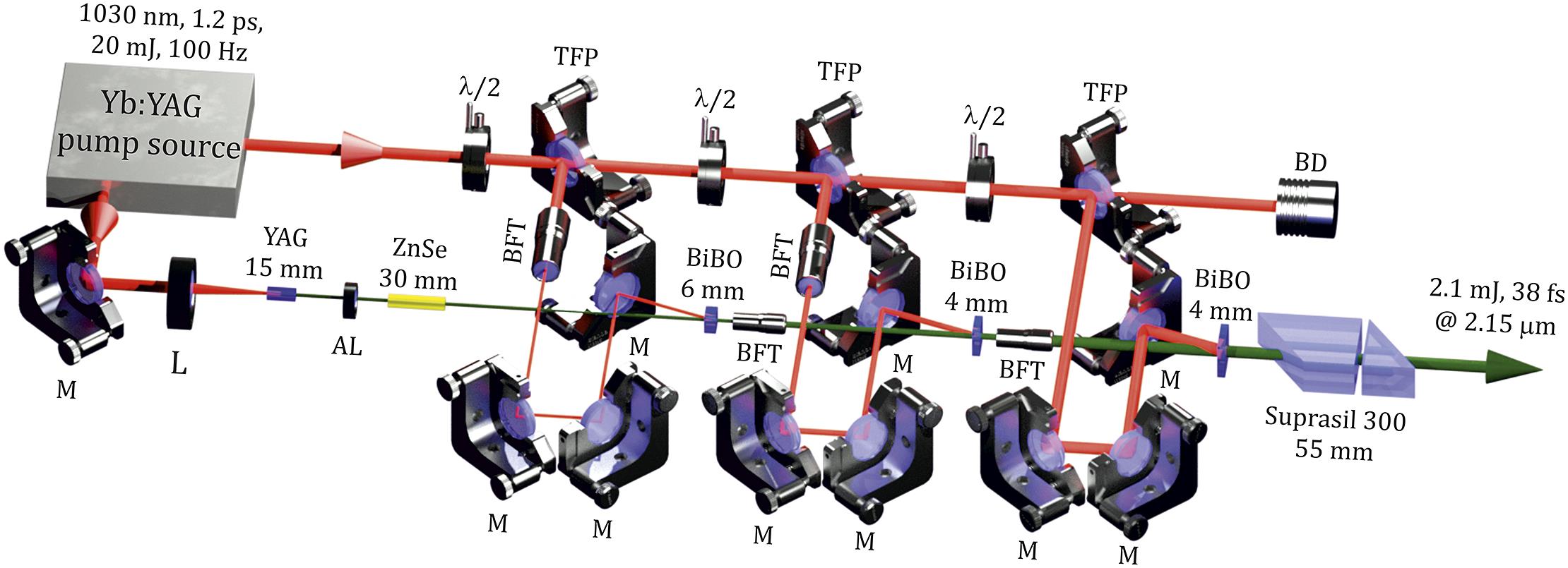
Figure 1.Experimental setup of the mJ-level OPCPA operating in the SWIR range. Yb:YAG, a two-stage CPA providing approximately 1.2 ps pulses at 1030 nm for OPCPA pumping and generating the SC seed in the YAG crystal; TFP, thin-film polarizer; λ/2, half-wave retardation plate; L, focusing lens; AL, achromatic lens; ZnSe, AR-coated ZnSe plate; M, HR1030 nm mirror; BFT, beam forming telescope; BiBO, nonlinear parametric crystal; Suprasil 300, a pair of glass prisms for pulse compression.
Seed pulses for the OPCPA were generated in YAG crystals of 15 or 130 mm long using only a small portion (~100 μJ) of the pump pulse. The energy of the incident pulse, the focal length and the position of the beam waist were optimized to achieve a uniform spectral envelope and the best energy stability of the SC. The range of incident energies, depending on the length of the crystal from 4 to 14 μJ, was chosen considering the thresholds for the generation of the SC and optical damage to the crystal. The generated SC was selected using a long-pass filter (Thorlabs FELH1200) and collimated with a parabolic mirror (Thorlabs MPD127165-90-P01). The energy stability of the SC pulses was measured using a Si photodetector and an oscilloscope with a bandwidth of 300 MHz (Tektronix DPO3034). Spectral measurements were performed using a spectrometer (Ocean Optics NIRQuest512-2.5) with an integration time of 100 ms.
SC pulses generated in YAG crystals of 15 or 130 mm long were amplified in a three-stage noncollinear OPCPA based on BiBO crystals (type-I, phase-matching angle θ = 8°) with antireflection coating in the range of 1750–2500 nm. The lengths of the BiBO crystals were chosen to achieve the best conversion efficiency at each stage without significantly narrowing the spectrum. In the case of SC generation in a 15 mm YAG crystal, to change the GDD sign, the seed pulse was additionally chirped in an antireflection coated ZnSe plate of 30 mm long. Most of the output energy of the Yb:YAG CPA (up to ∼11 mJ) was used to pump the OPCPA. The sizes of BiBO crystals were chosen for three stages of the OPCPA: 4 mm × 4 mm × 6 mm, 10 mm × 10 mm × 4 mm and 15 mm × 15 mm × 4 mm, respectively. The overall pump energy used was limited by the 15 mm × 15 mm aperture of the BiBO crystal in the last stage. The pulses amplified in the OPCPA were compressed in ZnSe or Suprasil 300 glass plates, depending on the sign of the chirp. The compressed pulses were directed to a self-made second harmonic generation (SHG) scanning frequency-resolved optical gating (FROG) device to determine the pulse width and spectral-temporal phase. It consisted of a thin broadband calcium fluoride beam splitter with a reflectance of 50% ± 5% in the wavelength range of 1–6 μm, a type-I BBO crystal 10 μm thick for SHG and a spectrometer (Ocean Optics, NIRQuest-512-2.5).
3 Experimental results and discussion
3.1 Supercontinuum generation in the SWIR wing
In YAG crystals of 15 and 130 mm long, the threshold energies of the pump pulse were determined to be 7 and 4 μJ, respectively, above which a significant broadening of the SC spectra was observed. The beam waist was imaged at a depth of 2 mm (for a short crystal) and 40 mm (for a long one) from the input face of the crystal. When the pump was focused by a lens with a focal length of f = 100 mm into a crystal 15 mm long, the SC spectrum expanded to approximately 2.4 μm (Figure 2(a)). In almost the entire range of pump energies, the maximum intensity of the spectrum envelope was distributed in the spectral range of the anomalous group velocity dispersion (GVD), since the zero-dispersion wavelength in YAG is 1.6 μm[32]. This means that the SC pulse exhibits a negative GDD in this spectral range[29].
![]()
Figure 2.Dependence of the intensity of the SC spectrum envelope on the pump pulse energy at different focal lengths for YAG crystals 15 mm (a)–(c) and 130 mm (d)–(f).
As the focal length increased, the intensity of the spectrum in this range decayed (Figures 2(b) and 2(c)). However, for a focal length of 100 or 150 mm, due to fluctuations in the energy of the pump pulses, significant spectral modulations of the SC seed were observed, especially in the range of 1.8–2.3 μm. On the other hand, when focusing with f = 200 mm, the SC spectrum retained a uniform distribution over the entire energy range. With an increase in the pump pulse energy, the long-wavelength wing of the spectrum shifted from approximately 1.6 μm to the wavelength range above 2 μm (Figure 2(c)). When the pump was focused by a lens f = 250 mm into a 130 mm YAG crystal, new spectral components appeared at a central wavelength of approximately 2 μm, mainly in the anomalous GVD range from 1.6 to 2.4 μm (Figure 2(d)). The shape of the spectral envelope remained unchanged over the entire energy range. Meanwhile, in the case of a longer focal length, modulations began to appear in the spectrum above 1.6 μm (Figures 2(e) and 2(f)), increasing with higher pump pulse energy. Above an energy of 7 μJ, spatial distortions appeared in the SC beam with deterioration in the stability of the pulse energy (Figure 3(b), green and red curves), which indicates the formation of another light filament.
![]()
Figure 3.Ratio of the energy stability of the SC and the pump pulse σSC/σPump as a function of the pump energy for different focusing into YAG crystals: (a) 15 mm and (b) 130 mm.
The goal was to determine the focusing conditions when the stability of the SC pulse energy would be the least sensitive to fluctuations in the pump pulse energy, that is, to find a vast ‘valley’ of stability. Thus, by varying the pump pulse energy, the stability (standard deviation, σSC) of the SC pulse area under the envelope was recorded with an oscilloscope and compared with the stability of the pump pulse energy σPump. The ratio of the energy stabilities of the SC and the pump pulse σSC/σPump as a function of the pump energy for different focusing conditions is shown in Figure 3. The widest stability valleys were observed with YAG crystals of 15 and 130 mm long at focal lengths of 200 and 250 mm, respectively (Figure 3). In the energy range of 9–13 μJ with a short crystal and 5–8 μJ with a long crystal, the stability of the SC pulse was 1.2 times better than that of the pump source. The optimal focusing conditions for a stable single-filament SC in the SWIR range with short and long YAG crystals are given in Table 1.
| YAG length [mm] | f [mm] | d [μm] | NA | Eth [μJ] | Ep [μJ] | L [mm] |
|---|---|---|---|---|---|---|
| 15 | 200 | 100 | 0.0075 | 8 | 11 | 2 |
| 130 | 250 | 130 | 0.006 | 4 | 6.5 | 40 |
Table 1. Optimal focusing conditions for stable SC generation in the SWIR spectral range.
Thus, under optimal conditions, fluctuations in the energy of the pump pulses lead only to instability of the position of the SC filament inside the crystal, while intensity limitation (due to multiphoton absorption) and chromatic dispersion maintained the filament length and intensity unchanged over a wide energy range[33]. This led to the stability of the SC spectrum envelope, the pulse energy and the spatial distribution. These conditions also ensured the daily repeatability of the SC parameters even with small changes in the pulse width or pump pulse energy. Long-term observations did not reveal any optical damage to the YAG crystal. The spatial profile of the SC beam at the output of the YAG crystals was close to Gaussian (insets in Figure 4).
![]()
Figure 4.SWIR wing of SC spectra under optimal excitation conditions in YAG crystals: (a) 15 mm and (b) 130 mm long. The insets show the corresponding beam profiles.
Since the leading subpulse is responsible for the long-wavelength wing of the SC spectrum, there are differences in the nonlinear propagation and its temporal transformation in the wavelength range of the anomalous GVD[34]. As a result, under optimal focusing conditions, it strongly depended on the crystal length. The intensity of the long-wavelength wing of the SC in a short crystal steadily decreased from the excitation wavelength down to 1% at 2.1 μm (Figure 4(a)). The SC spectrum from a long YAG, in contrast, extended up to 1.5–2.4 μm at an intensity level of more than 10−2 (Figure 4(b)), which is in good agreement with the OPCPA bandwidth when pumped at a wavelength of 1 μm[30]. On the other hand, despite the lower spectral intensity of the SC with a short YAG crystal, the smaller GDD accumulated means it is easy to change its sign using a material with positive dispersion in the SWIR spectral range, such as ZnSe, GaAs and CdSe. This provides an advantage in the development of cost-effective compressors. Thus, the choice of the OPCPA seed source (in our case, a YAG crystal 130 or 15 mm long) is convenient with picosecond pump pulses. It is possible to use both pulses with a more intense spectrum at 1.8–2.5 μm and negative GDD from 130 mm YAG, as well as pulses with a lower GDD from 15 mm YAG and vary their dispersion in a solid material. Compressors can vary while maintaining compactness and simplicity.
3.2 Low-energy OPCPA investigation
Two different single-stage OPCPA configurations were investigated at low pump energy (Figure 5). In both cases, the angle between the pump and the SC seed was minimal (<2° inside the BiBO), and the phase-matching bandwidth was maximized by tuning the pump incidence angle to θ = 8°. The noncollinear configuration also allows the spatial separation of the signal and idler pulses after amplification.
Figure 6(a) shows the spectrum of a signal amplified in the single-stage OPCPA. Regardless of the chosen length of the YAG crystal (130 or 15 mm) used to generate the SC pulses, the spectrum of the amplified signal extended from approximately 1.9 μm to approximately 2.5 μm with a spectral bandwidth of approximately 460 nm (full width at half maximum (FWHM)), which corresponds to a transform-limited pulse width of 25 fs (Figure 6(a) inset), that is, less than four cycles at 2.2 μm. At a pump intensity of 52 GW/cm2, the maximum signal energy of approximately 14 μJ and conversion efficiency of 5.1% (Figure 6(b), solid line) were achieved in a single OPCPA stage seeded with an SC from a long YAG crystal. A further increase in the pump energy above the saturation level led to distortion of the spatial and temporal profiles of the signal pulse. The amplified signal was negatively chirped up to approximately 500 fs due to GDD accumulation in the relatively long YAG and BiBO crystals. In the case of an SC seed from a short YAG crystal, the signal pulse was stretched only to approximately 100 fs, and saturation of the pump-to-signal conversion efficiency was achieved at a much higher pump intensity of 80 GW/cm2 (Figure 6(b), dotted line). This led to a decrease in the conversion efficiency to 2.6% and the maximum output signal energy to 9 μJ. To improve the conversion efficiency to 4% (Figure 6(b), dashed line), the SC seed was chirped to approximately 500 fs by adding a positive GDD of 6600 fs2 in the ZnSe plate (Figure 5(b)). No significant spectral narrowing of the amplified signal was observed. Despite similar signal pulse widths in both configurations, approximately 20% higher efficiency and output energy were achieved with the longer YAG crystal, most likely due to the higher SC spectral intensity.
![]()
Figure 5.Single-stage OPCPA configurations with (a) short and (b) long YAG crystals for SC generation.
![]()
Figure 6.(a) Output spectrum of the first OPCPA stage with SC seed from a 130 mm long YAG crystal. Inset, transform-limited temporal shape, calculated from the measured spectra. (b) Pump-to-signal conversion efficiency in the first OPCPA stage with SC seed from a YAG crystal 130 mm long (solid line) and 15 mm long (dotted line), as well as with an additional chirp in a 30 mm ZnSe plate (dashed line).
Since the signal can be positively or negatively chirped depending on the configuration, this simplifies the selection of the optimal compressor for high-energy OPCPAs. Because the seed picks up a relatively small amount of GDD, we chose a bulk compressor to control dispersion due to its high transmission and compactness. All materials exhibit a positive TOD in the SWIR range, while GDD may have the opposite sign for different materials. Although ZnSe has zero dispersion at approximately 4800 nm, it exhibits a very large nonlinear refractive index n2. Therefore, the maximum aperture of commercially available ZnSe plates is usually insufficient to maintain peak power below the threshold of competing nonlinear effects in mJ-level pulse compressors. They are commonly used as pulse stretchers before amplification stages or as a compressor in OPCPA systems with high average but low peak power[11]. On this basis, it was determined that further compression of the positively chirped pulse should be carried out in Suprasil 300 glass with negative GDD in the SWIR range, which also has n2 about two orders of magnitude lower than that of ZnSe. Taking into account the GDD values of YAG (15 mm), ZnSe (30 mm) and BiBO (6 mm) crystals (Figure 5(b)), it was found that a glass length of 55 mm is required for the ultimate compression of amplified signal pulses.
The achieved pulse width of 47 fs (FWHM) was 1.9 times the transform-limited pulse due to the residual TOD. Even with full GDD compensation for such a broadband chirped pulse, the uncompensated TOD (~55,000 fs3) results in tail pulses that account for about 35% of the main pulse energy (Figure 7, solid line). It is noteworthy that after compression of the negatively chirped signal (Figure 5(a)) in ZnSe, a similar pulse shape was obtained. Obviously, the dispersion and its sign for the SC in a long YAG do not have a large effect on the final pulse compression. Therefore, to ensure linear compression in a bulk material, even at more than an order of magnitude lower TOD compared to OPCPA systems pumped in tens or hundreds of picoseconds[22], higher-order dispersion compensation becomes important to obtain high-contrast, high-energy, few-cycle pulses in the SWIR range. In this case, specially designed chirped mirrors with both GDD and TOD compensation can be used. Moreover, more expensive schemes with an AOPDF as a stretcher and bulk material or chirped mirrors as a compressor can be used. However, in order to develop a cost-effective high-energy OPCPA, we decided to reduce the bandwidth and explore GDD-only compensating compression.
![]()
Figure 7.SHG-FROG retrieved temporal profile (solid line) and temporal phase (dashed line) of an amplified signal pulse after compression in Suprasil 300 with SC seed from a 15 mm YAG crystal compared to a transform-limited pulse calculated from the measured spectrum (dotted line).
3.3 High-energy OPCPA investigation
Тo narrow the gain bandwidth in the high-energy OPCPA (Figure 1), we detuned the phase matching in all three stages. Correspondingly, the spectrum of amplified pulses spanned from approximately 1.95 μm to approximately 2.4 μm with a bandwidth corresponding to the transform-limited pulse width of 35 fs (Figure 8(a), inset), that is, less than five cycles at 2.15 μm center wavelength. Based on our calculations and low-energy OPCPA investigations, the spectral bandwidth of the amplified signal was narrow enough to reduce the residual effect of higher-order dispersion on the temporal shape of the compressed pulse. After the second OPCPA stage, the signal pulses were amplified up to 250 μJ with a pump-to-signal efficiency of 14%, reaching saturation level at a pump power intensity of 35 GW/cm2. It is noteworthy that we did not observe superfluorescence during amplification in each stage. However, when the pump pulse energy exceeded saturation of the conversion efficiency, superfluorescence was noticeable in the first and second stages. For the final OPCPA stage, a pump pulse energy of approximately 9 mJ was used. Due to the high signal energy, the pump intensity was reduced to approximately 30 GW/cm2, which was close to the saturation level. The energy of the amplified signal reached 2.25 mJ (Figure 8(b)) with a pump-to-signal conversion efficiency of approximately 25%. It should be noted that the noncollinear degenerate OPCPA also produces approximately 2.1 μm angularly dispersed idler pulses that have the same pulse energy, polarization and spectral bandwidth as the amplified signal pulses. The idler pulse has a frequency chirp sign opposite to the signal pulse and can be independently compressed using Si/ZnSe blocks. Therefore, the total energy available at a wavelength of 2.15 μm from the signal and idler pulses reached approximately 4.5 mJ with a total conversion efficiency of approximately 50%. The far-field beam profile of the amplified signal was measured by two-photon excitation using a Si-complementary metal-oxide semiconductor (CMOS) camera at the focus of a 750 mm CaF2 lens. At the maximum output energy, the beam had a Gaussian intensity profile, which means that there was no significant back conversion (Figure 8(b), inset).
![]()
Figure 8.(a) Output spectrum of a high-energy OPCPA. Inset, transform-limited temporal pulse shape calculated from the measured spectra. (b) Output energy versus the pump pulse energy in the final OPCPA stage. Inset, normalized beam profile in the far field at 2.15 μm at maximum output energy.
The output energy stability StDev ±4% (Figure 9(a)) was observed for 30 min of operation without a protective cover in air flows from the filters. Without beam pointing or jitter stabilization, the observed energy stability was only approximately two times worse than of the pump laser. Although there was still an unused pump energy of approximately 10 mJ, we did not increase the pump pulse energy in the last OPCPA stage due to saturation in the BiBO crystal with the maximum available aperture. Thus, a further increase in output energy can be achieved with larger aperture nonlinear crystals. At the time of the experiments, we could not find BiBO crystals larger than 15 mm × 15 mm; however, in the last OPCPA stage, an yttrium calcium oxyborate (YCOB) crystal with a size of 20 mm × 20 mm can also be used[22], although with a lower conversion efficiency. In order to use all the available pump energy, a shorter BiBO crystal can also be used in the last OPCPA or additional stage. However, in this case, the overall efficiency will be reduced.
![]()
Figure 9.(a) Amplified output energy stability of the OPCPA system for 30 min of operation. (b) SHG-FROG retrieved temporal profile (solid line) and temporal phase (dashed line) of the compressed signal pulse at maximum output energy compared to the transform-limited pulse calculated from the measured spectrum (dotted line).
After three stages of the OPCPA, a chirped signal pulse width of 420 fs (FWHM) was observed. For the final pulse compression, two Suprasil 300 glass blocks were used, the input and output faces of which were cut at the Brewster angle for the first and second compressions, respectively (Figure 1). The blocks were placed at the appropriate angle by adjusting the propagation length in the material with a resulting GDD of –5100 fs2. Losses due to reflections on the glass surface reduced the output energy to approximately 2.1 mJ (
4 Conclusions
We present the results of a study of a passively synchronized mJ-level, few-cycle SWIR OPCPA pumped by a picosecond Yb:YAG CPA laser. This OPCPA was seeded with SWIR SC wing pulses excited by the same laser in YAG crystals 15 and 130 mm long. The amplification of the SC pulses was first studied in two different single-stage OPCPA configurations operating with the opposite GDD sign. An improvement in the pump-to-signal conversion efficiency and an increase in output energy of more than 20% were achieved with a long YAG crystal, possibly due to the higher seed spectral intensity. Regardless of the YAG crystal length, the amplified pulse spectrum supported a transform-limited pulse width of 25 fs (<4 cycles) at a central wavelength of 2.2 μm. The residual dispersion after compression in the bulk material limited the pulse width to 47 fs. Then, a high-energy OPCPA was developed with an output energy of approximately 2.1 mJ and a signal-to-pump conversion efficiency of up to 25% in the last stage. The signal pulses amplified in the OPCPA were compressed in a glass block to 38 fs, which is close to the limit of 35 fs. The resulting peak power is estimated at approximately 47 GW, which can be scaled up to more than 80 GW using adaptive phase control with compression down to less than 30 fs, but at a much higher cost. Additional opportunities to increase the energy conversion efficiency at even longer wavelength up to approximately 2.25 μm are provided by hybrid OPCPA/TSRCPA configurations[36].
References
[1] P. Agostini, L. F. DiMauro. Rep. Prog. Phys, 67, 813(2004).
[2] M. Clerici, M. Peccianti, B. E. Schmidt, L. Caspani, M. Shalaby, M. Giguere, A. Lotti, A. Couairon, F. Legare, T. Ozaki, D. Faccio, R. Morandotti. Phys. Rev. Lett., 110, 253901(2013).
[3] W. Li, X. Zhou, R. Lock, S. Patchkovskii, A. Stolow, H. C. Kapteyn, M. M. Murnane. Science, 322, 1207(2008).
[4] M. G. Pullen, B. Wolter, A. T. Le, M. Baudisch, M. Hemmer, A. Senftleben, C. D. Schröter, J. Ullrich, R. Moshammer, C. D. Lin, J. Biegert. Nat. Commun., 6, 7262(2015).
[5] R. A. Richter, N. Tolstik, S. Rigaud, P. D. Valle, A. Erbe, P. Ebbinghaus, I. Astrauskas, V. Kalashnikov, E. Sorokin, I. T. Sorokina. J. Opt. Soc. Am. B, 37, 2543(2020).
[6] I. Jordan, M. Huppert, M. A. Brown, J. A. van Bokhoven, H. J. Wörner. Rev. Sci. Instrum., 86, 123905(2015).
[7] N. Saito, H. Sannohe, N. Ishii, T. Kanai, N. Kosugi, Y. Wu, A. Chew, S. Han, Z. Chang, J. Itatani. Optica, 6, 1542(2019).
[8] B. Vodungbo, J. Gautier, G. Lambert, A. B. Sardinha, M. Lozano, S. Sebban, M. Ducousso, W. Boutu, K. Li, B. Tudu, M. Tortarolo, R. Hawaldar, R. Delaunay, V. López-Flores, J. Arabski, C. Boeglin, H. Merdji, P. Zeitoun, J. Lüning. Nat. Commun., 3, 999(2012).
[9] P. B. Corkum, F. Krausz. Nat. Phys., 3, 381(2007).
[10] G. Herinck, D. R. Solli, M. Gulde, C. Ropers. Nature, 483, 190(2012).
[11] J. Pupeikis, P. A. Chevreuil, N. Bigler, L. Gallmann, C. R. Phillips, U. Keller. Optica, 7, 168(2020).
[12] C. Schmidt, Y. Pertot, T. Balciunas, K. Zinchenko, M. Matthews, H. J. Wörner, J. P. Wolf. Opt. Express, 26, 11834(2018).
[13] D. Kracht, H. Sayinc, S. Yilmaz, M. Wysmolek, K. Hausmann, C. Ottenhues, D. Wandt, A. Wienke, J. Neumann. Phys. Procedia, 83, 1184(2016).
[14] V. Cardin, N. Thiré, S. Beaulieu, V. Wanie, F. Légaré, B. E. Schmidt. Appl. Phys. Lett., 107, 181101(2015).
[15] Y. Wu, F. Zhou, E. W. Larsen, F. Zhuang, Y. Yin, Z. Chang. Sci. Rep., 10, 7775(2020).
[16] T. Balciunas, C. Fourcade-Dutin, G. Fan, T. Witting, A. A. Voronin, A. M. Zheltikov, F. Gerome, G. G. Paulus, A. Baltuska, F. Benabid. Nat. Commun., 6, 6117(2015).
[17] K. Murari, G. Cirmi, H. Cankaya, G. J. Stein, B. Debord, F. Gérôme, F. Ritzkosky, F. Benabid, O. Muecke, F. X. Kärtner. Photon. Res., 10, 637(2022).
[18] P. Gierschke, C. Grebing, M. Abdelaal, M. Lenski, J. Buldt, Z. Wang, T. Heuermann, M. Mueller, M. Gebhardt, J. Rothhardt, J. Limpert. Opt. Lett., 47, 3511(2022).
[19] C. J. Lai, K. H. Hong, J. P. Siqueira, P. Krogen, C. L. Chang, G. J. Stein, H. Liang, P. D. Keathley, G. Laurent, J. Mose. J. Opt., 17, 094009(2015).
[20] F. Silva, P. K. Bates, A. Esteban-Martin, M. Ebrahim-Zadeh, J. Biegert. Opt. Lett., 37, 933(2012).
[21] T. Feng, A. Heilmann, M. Bock, L. Ehrentraut, T. Witting, H. Yu, H. Stiel, S. Eisebitt, M. Schnürer. Opt. Express, 28, 8724(2020).
[22] K. H. Hong, S. W. Huang, J. Moses, X. Fu, C. J. Lai, G. Cirmi, A. Sell, E. Granados, P. Keathley, F. X. Kärtner. Opt. Express, 19, 15538(2011).
[23] Y. Deng, S. Alexander, H. Fattahi, M. Ueffing, X. Gu, M. Ossiander, T. Metzger, V. Pervak, H. Ishizuki, T. Taira, T. Kobayashi, G. Marcus, F. Krausz, R. Kienberger, N. Karpowicz. Opt. Lett., 37, 4973(2012).
[24] L. Xu, B. Xue, N. Ishii, J. Itatani, K. Midorikawa, E. Takahashi. J. Opt. Lett., 47, 3371(2022).
[25] I. Sytcevich, A. L. Viotti, C. Guo, J. Vogelsang, F. Langer, A. L’Huillier, C. L. Arnold. Opt. Express, 30, 27858(2022).
[26] T. Fuji, N. Ishii, C. Y. Teisset, X. Gu, T. Metzger, A. Baltuska, N. Forget, D. Kaplan, A. Galvanauskas, F. Krausz. Opt. Lett., 31, 1103(2006).
[27] N. Thiré, R. Maksimenka, B. Kiss, C. Ferchaud, P. Bizouard, E. Cormier, K. Osvay, N. Forget. Opt. Express, 25, 1505(2017).
[28] P. Mackonis, A. Petrulenas, V. Girdauskas, A. M. Rodin. 2019 Conference on Lasers and Electro-Optics Europe and European Quantum Electronics Conference(2019).
[29] V. Jukna, J. Galinis, G. Tamosauskas, D. Majus, A. Dubietis. Appl. Phys. B, 116, 477(2014).
[30] N. Ishii, M. Maruyama, K. Nagashima, Y. Ochi, R. Itakura. Opt. Express, 29, 17069(2021).
[31] P. Mackonis, A. M. Rodin. Opt. Express, 28, 1261(2020).
[32] A. L. Calendron, H. Cankaya, G. Cirmi, F. X. Kärtner. Opt. Express, 23, 13866(2015).
[33] A. Špacek, L. Indra, F. Batysta, P. Hříbek, J. T. Green, J. Novák, R. Antipenkov, P. Bakule, B. Rus. Opt. Express, 28, 20205(2020).
[34] J. Galinis, G. Tamošauskas, I. Gražuleviciute, E. Keblyte, V. Jukna, A. Dubietis. Phys. Rev. A, 92, 033857(2015).
[35] E. Ridente, M. Weidman, M. Mamaikin, C. Jakubeit, F. Krausz, N. Karpowicz. Optica, 7, 1093.
[36] A. Petrulenas, P. Mackonis, A. M. Rodin. , , and , Opt. Lett. , 1598 (2023)., 48.

Set citation alerts for the article
Please enter your email address
© Copyright 2018-2021 | Chinese Laser Press. All Rights Reserved 沪ICP备15018463号-20