
Zilin Zhao, Daping Luo, Yang Liu, Zejiang Deng, Lian Zhou, Gehui Xie, Chenglin Gu, Yanzhao Yang, Bin Wu, Wenxue Li. Tunable compact asynchronous optical sampling system using Er-doped fiber laser[J]. High Power Laser Science and Engineering, 2023, 11(2): 02000e29
- High Power Laser Science and Engineering
- Vol. 11, Issue 2, 02000e29 (2023)
Abstract
1 Introduction
As a powerful tool, femtosecond lasers with ultrashort pulses and high peak power have been used in numerous spectroscopic applications[1–3], especially in the THz range[4]. Combined with the pump-probe method, it can be a powerful technique for material characterization and precision metrology, as demonstrated in terahertz time-lapse spectroscopy[5,6], multi-heterodyne spectroscopy[7] and absolute distance measurement[8]. Traditional terahertz time-domain spectroscopy (THz-TDS) has been achieved using translation stages, but this method is limited by the scanning speed and instability due to mechanical vibrations. Therefore, optical sampling by cavity tuning (OSCAT) has been proposed[9–11] to improve the scanning speed. This method introduces a variable time delay by the dither of the laser cavity length. The advantages of OSCAT are its customizable scanning speed and simple structure, but it still has inherent vibrational noise. To overcome this limitation due to propagating through the same laser cavity, a single-cavity dual-comb laser (SCDCL) was applied in THz-TDS[12–14]. This method does not require mechanical delay lines and can obtain a spectrum with resolution in the MHz order[15], but the structure of the SCDCL limits the adjustable range of the repetition rate offset.
Asynchronous optical sampling (ASOPS) is another promising solution that employs two mode-locked lasers with slightly different repetition rates to generate and detect pulsed THz radiation[16–20]. Conventionally, Ti:sapphire lasers have been widely used as laboratory light sources for high-speed THz-TDS[21,22]. Polarization-maintaining (PM) fiber lasers feature characteristics that improve the stability and robustness of THz-TDS[23]. Moreover, the fiber laser can be directly connected to a photoconductive antenna (PCA) to generate a THz comb[24,25], which enables the flexible positioning and installation of the measurement head without using several lenses and mirrors. The adaptive sampling method with two free-running lasers is another ASOPS technique that can achieve a spectral resolution similar to that of the phase-locked dual-comb system[26]. Nevertheless, the repetition rate of this method fluctuates rapidly, which cannot provide stable absolute accuracy of the spectral frequency. By contrast, the spectral accuracy of the ASOPS system, in which the repetition rates of the two lasers are precisely controlled, is traceable to atomic clocks. Such ASOPS systems have been used in burn diagnostics[27], THz spectroscopy measurements[28], THz frequency synthesizers[29] and absolute frequency measurements of continuous-wave terahertz radiation[30,31]. Furthermore, the adjustment range of the repetition rate of the ASOPS system is significant for spectrally interleaved[32] and THz ranges. Therefore, a compact and movable ASOPS system with a sufficiently tunable repetition rate is desirable for THz-TDS applications.
In this study, we demonstrated a movable ASOPS system employing two compact, tunable, all-PM fiber lasers. The fiber delay line (FDL) in the laser cavity can provide a tunable range of 0–1.25 MHz at a repetition rate of 100 MHz. Utilizing phase-locked loops (PPLs) and temperature controller loops, the offset Δf between the oscillators was tightly locked. The standard deviation of the offset Δf was 7.28 mHz with 7.13 × 10⁻¹¹ fractional instability at an average time of 1 s. Direct-digital synthesis (DDS) in PPLs can provide an adjustable Δf at a repetition rate of 100 MHz. The all-PM fiber design improves the system’s robustness and resistance to environmental disturbances. Its capabilities in the THz regime were demonstrated by the THz-TDS, achieving a spectral bandwidth of 3 THz and a dynamic range of 30 dB. Benefiting from the relatively large tunable range of the system with fr exceeding six orders of magnitude, it can be applied to spectrally interleaved dual-THz comb spectroscopy and several different THz-TDS experiments that require different Δf values.
Sign up for High Power Laser Science and Engineering TOC. Get the latest issue of High Power Laser Science and Engineering delivered right to you!Sign up now
2 Experimental setup
In the THz-TDS experiments, the ASOPS system employed two mode-locked fiber lasers as the pump and probe lasers, which operated in a master–slave configuration with near-repetition rates of fM and fS, as shown in Figure 1. In the time domain, the pulses emitted by the two lasers experienced automatic scanning because of the repetition rate offset Δf = fM − fS and because the scanning period (T) equals 1/Δf. The time interval (Δτ) between the two pulses is given by the following:
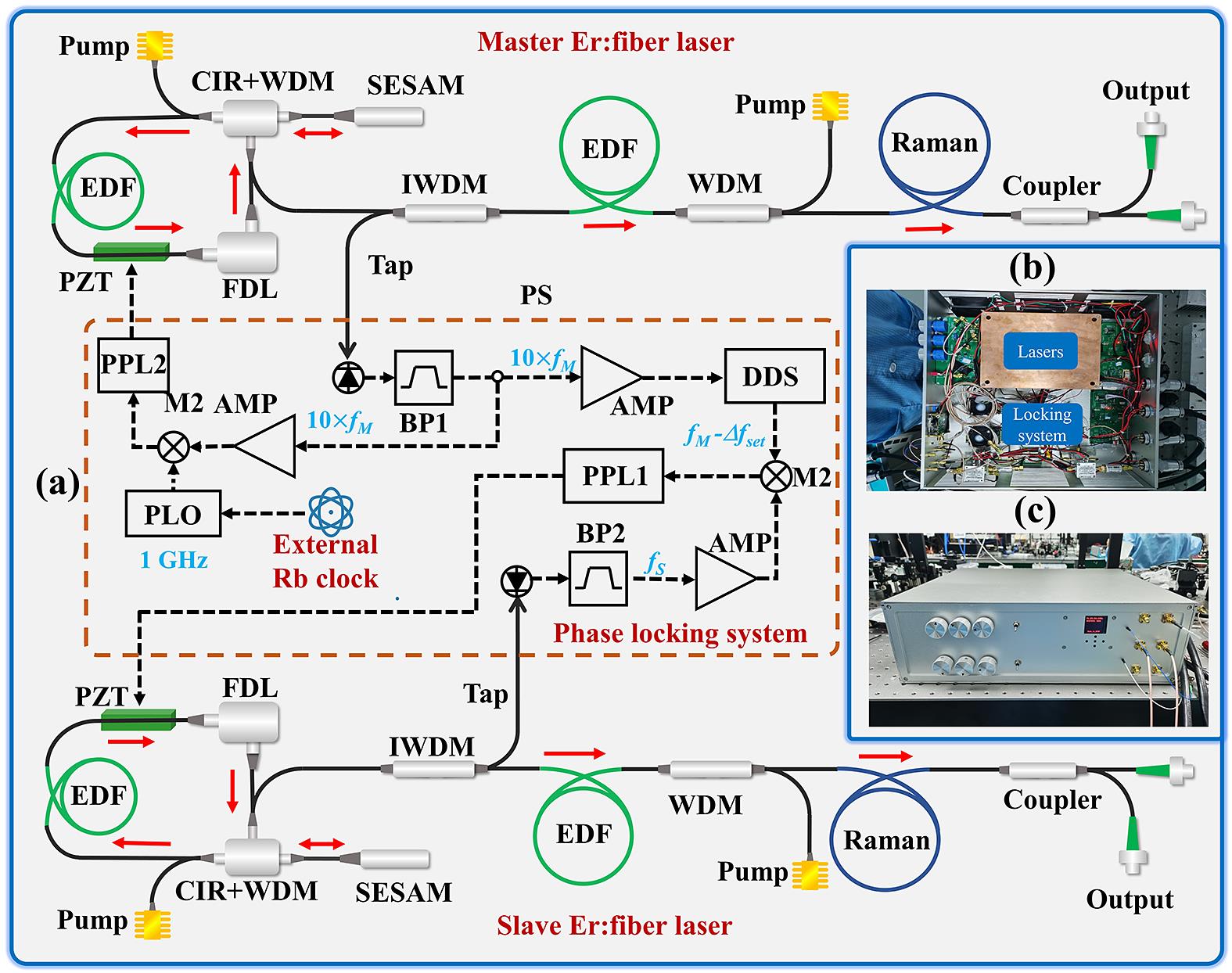
Figure 1.(a) Setup of the ASOPS system. CIR+WDM, 980/1550 nm wavelength-division multiplexer fiber circulator; EDF, Er-doped fiber; SESAM, semiconductor saturable absorption mirror; PZT, piezoelectric transducer; FDL, electrically controlled fiber delay line; IWDM, wavelength-division multiplexer with isolator; PD, fiber-coupled photodiode; Raman, polarization-maintaining Raman fiber; PS, power splitter; PLO, phase-locked oscillator; DDS, direct-digital synthesis component; BP, electronic band-pass filter; AMP, amplifier; M1 and M2, electronic mixers; PLL1 and PPL2, phase-locked loops;
where fM/Δf is the temporal magnification factor of the ASOPS experiment that determines the frequency scaling of the spectrum. The time interval Δτ is determined by the repetition rate offset Δf, which also represents the time resolution of the ASOPS system.
Figure 1(a) shows a detailed diagram of the experimental setup of the ASOPS system, which consists of two custom-made Er-doped mode-locked fiber lasers, two PPLs and two temperature control loops. The two lasers employed Er-doped fiber (EDF) ring oscillators mode-locked by a semiconductor saturable absorption mirror (SESAM). In addition, the oscillator contained a PM wavelength-division multiplexer (WDM) fiber circulator (WDM+CIR) with an integrated 30% output tap, a 39-cm PM EDF (LIEKKI, Er80-4/125-HD-PM) and an electrically controlled FDL. The FDL provided an optical path adjustment of 4 cm in the oscillators, which resulted in an approximate 1.25 MHz adjustment amount at a 100 MHz repetition rate. To lock the repetition rate, a section of the PM1550 fiber in the cavity was glued to a piezoelectric transducer (PZT) with a modulation bandwidth of 1 kHz. The pulses from the oscillator were fed into an isolator WDM (IWDM) with an output tap, which could split 10% of the pulse energy for a repetition rate locking system. The remaining pulse energy was fed into a 1.5-m-long Er-80 fiber amplifier with a back-pumped configuration. To meet the requirements for THz PCAs, the positively chirped pulse from the EDF amplifier was first stretched in the positive-dispersion Raman fiber (PM Raman optical fiber P/N: 27313) and then compressed to less than 100 fs in the negative-dispersion fiber. Moreover, a fiber coupler split 10% of the output light to generate a beat note signal as the trigger signal, and 90% of the output light was delivered to the THz antenna modules via a 2.5 m optical fiber.
To improve the performance of the ASOPS system, two PLL systems were built to precisely synchronize Δf = fM − fS between the master and slave lasers, as shown in the red dashed box in Figure 1(a). In the initialization, the FDLs of two lasers can be adjusted automatically according to the predetermined repetition rates by the use of computer programs. Then, the output pulses from the 10% tap of each oscillator were fed into two fiber-coupled photodiodes to detect their repetition-rate signals. Considering that the DDS device had a maximum clock frequency of 1 GHz, the 10th harmonic of the repetition rate 10 × fM of the signal of the master laser was filtered out using the 1-GHz band-pass filter BP1. The DDS allowed an arbitrary selection of the output frequency of approximately 100 MHz, and its output frequency was set to fM − Δfset. The 100-MHz band-pass filter (BP2) filtered out the repetition rates fS of the slave laser. Subsequently, this signal was boosted by the following radio-frequency (RF) power amplifier. It was mixed with the signals from the DDS at the electronic mixer M2, generating an error signal of Δf − Δfset. This error signal was then delivered to the PLL1 feedback circuit, which modulated the PZT to control the repetition rate of the slave laser. The PLL2 was used to lock the absolute repetition rate of the master laser. A standard signal of 1 GHz, generated by the phase-locked oscillator (PLO) referencing a rubidium clock, was delivered into M1 to generate the error signal after being compared with the signal 10 × fM from BP1, realizing the repetition rate locking of the master laser. As shown in Figure 1(b), these PLLs consisted of a proportional integrating controller and a ±150 V high-voltage amplifier. Finally, the synchronization of the repetition rates between the two lasers was accomplished.
To further reduce the influence of the external environment, the ASOPS system had an integrated enclosure and its temperature was controlled. Utilizing the excellent thermal conductivity of copper, we have made a copper box to enclose the master laser, including the oscillator and fiber amplifier, as shown in Figure 1(b). To facilitate the temperature control of the operating laser, we attached a thermoelectric cooler (TEC) to the outer bottom of the copper box via the thermally conductive silicone while the thermistor was placed inside the copper box. The same operation was undertaken for the slave laser. The temperature control loops consisted of a TEC, thermistor and feedback circuit, which could maintain the temperature of the two operating lasers at 24° ± 0.01°. In addition, the entire system setup, including circuits and optical parts, was enclosed in a closed aluminum box with a total volume occupancy of 380 mm × 410 mm × 126 mm (3U chassis), which is smaller than that of the commercially available ASOPS system, as shown in Figure 1(c).
3 Results and discussion
To characterize our ASOPS system, we measured its temporal, spectral and power properties, which affect the THz radiation of ASOPS systems. The oscillators delivered a pulse train at a 1565 nm central wavelength with 24 mW average output power, which was limited by the damage threshold of the PCA. As shown in Figures 2(a) and 2(c), the spectral full width at half maximum (FWHM) of the master and slave lasers was 61 and 40 nm, respectively, after exiting a 2.5-m-long transmission fiber. The pulse durations of the master and slave lasers were separately compressed to 83 and 96 fs, respectively, with Gaussian fitting, as shown in Figures 2(b) and 2(d). The differences between the temporal and spectral profiles were dependent on the difference in the nonlinearity of the two pulses due to the slight difference in the lengths of the gain and Raman fibers in the two laser cavities and fiber amplifiers. The nonlinearity, accumulating in the amplifier and long transmission fiber, was the main contributor to the pedestals in two autocorrelation curves.
![]()
Figure 2.Spectra of the (a) master and (b) slave lasers centered at 1565 nm. Autocorrelation traces of the (c) master and (d) slave lasers. The dashed lines represent the Gaussian curves fitted to the autocorrelation traces.
The instability of fr and Δf in the ASOPS system caused fluctuations in the temporal magnification factor, affecting precision and accuracy. To characterize the frequency stability of the ASOPS system, we measured the repetition rate of the master and slave lasers using a frequency counter, referencing a Rb atomic clock in the system, for 5.5 h at a gate time of 1 s. Repetition rates fM and fS were phase-locked at 100 MHz by tuning the DDS and FDL. The original data of fM and fS are shown in Figures 3(a) and 3(d), with the calculated standard deviations of 2.16 and 6.95 mHz, respectively. Figures 3(b) and 3(e) show histograms with Gaussian profiles of fM and fS. Then, the overlapping Allen deviation of fM was calculated as 2.04 × 10⁻¹¹ and 7.09 × 10⁻¹³ at average times of 1 and 1000 s, respectively, as shown in Figure 3(c). The fractional instability of fS was 6.68 × 10⁻¹¹ and 1.69 × 10⁻¹² at average times of 1 and 1000 s, respectively, as shown in Figure 3(f). The original data of the repetition rate offset of the two lasers are shown in Figure 3(g); Δf stayed in the range of ±0.03 Hz with a standard deviation of 7.28 mHz. Figures 3(h) and 3(i) show the histogram and overlapping Allan deviation of Δf, respectively. The fractional instability of Δf was improved from 7.13 × 10⁻¹¹ to 1.98×10⁻¹² at an average time below 1000 s. This instability is limited by unwanted flicker frequency noise and the PLO referencing the Rb clock[33]. In addition, these results indicate that the repetition rate of the slave laser is tightly phase-locked to that of the master laser.
![]()
Figure 3.Recorded repetition rates of (a) master laser
Phase noise is another important parameter of ASOPS systems, so the phase noise of the locked-mode system was measured by a noise analyzer (R&S FWSP8), as shown in Figure 3(j). The integrated residual phase noise of the master laser repetition rate after locking was 10.2 mrad (1 Hz–1 MHz), which was determined by the PLO referencing the Rb clock[34]. The integrated residual phase noise of the slave laser repetition rate after locking was 10.3 mrad (1 Hz–1 MHz). The phase noise of both lasers was controlled at the same level; thus, the master and slave lasers were tightly locked together. The phase-locked and temperature control loops suppressed the phase noise at frequencies less than 1 kHz, which was caused by thermal noise and technical noise. Moreover, owing to quantum and white noises, the rejection of phase noise greater than 1 kHz in the high-frequency regime was limited by the PLL feedback bandwidth. In future work, this problem can be solved by adding an electro-optic modulator with a higher feedback bandwidth and using a better reference source.
The most attractive property of our ASOPS system is the wide tuning range of fr, which enables the system to be suitable for different THz-TDS applications. By leveraging the regulation capability of the FDL in the laser cavity, the repetition rates of both lasers can be tuned in the range of 99.86–101.11 MHz as the RF spectrum of fS, as shown in Figure 4(e). Moreover, the tuning range of 0 –1 MHz of the difference between the two lasers, Δf, was realized by employing a DDS, spanning over six orders of magnitude, with a fixed repetition rate of the master. The maximum travel range of the FDL mainly limited the tuning range of the ASOPS system. The adjustment process for the repetition rate of the slave laser was recorded using a frequency counter, as shown in Figure 4(d). Subsequently, a coupler with a split ratio of 5:5 combined the two lasers, and a combination beam was coupled to a fiber-coupled photodiode to measure the interference signal. Figures 4(a)–4(c) show the time-domain interference signals with Δf values of 100, 200 and 300 Hz, respectively. This flexibility adjustment of fr enables the system to be used in applications requiring a reconfigurable dynamic range, such as spectrally interleaved dual-THz comb spectroscopy and absolute distance measurement using the THz time-of-flight technique.
![]()
Figure 4.Time-domain interference signals of the ASOPS system with Δ
We established a TDS spectrometer, shown in Figure 5(a), to study its utility. This system consisted of an ASOPS module and a THz generation detection module (Menlo THz Purge Box), which were connected by an optical fiber. The fM and Δf of the ASOPS system were set to 100 MHz and 5 Hz, respectively. The output lights of the two lasers were connected to a 1:1 fiber coupler to generate the beat note signal, which was fed to a digitizer as a trigger signal for data acquisition. Most of the output light from the master laser was used as pump light and delivered to the THz emitting PCA to generate THz radiation. The emitted THz pulses propagated in free space through a pair of off-axis parabolic mirrors and were then delivered to the THz detection PCA. The output light from the slave laser acted as the probe light and entered the THz detection PCA through the optical fiber to generate an electrical signal. This electrical signal was amplified by a current preamplifier (AMP) and then delivered to the digitizer to obtain the THz radiation signal. Figure 5(b) shows the measured temporal profile of the THz pulse after averaging 50 sweeps. The power spectrum of the THz pulse was also obtained using the fast Fourier transform of the temporal profile, as shown in Figure 5(c). The spectral span ranged from 0 to 3 THz with a dynamic range of 30 dB. This result demonstrates the suitability of our ASOPS system in the field of THz-TDS, and the frequency scale of this spectrum is traceable to the rubidium frequency standard.
![]()
Figure 5.(a) Experimental setup of the TDS spectrometer. (b) Temporal waveform and (c) power spectrum of the pulsed THz radiation obtained at a 50-sweep measurement.
4 Conclusions
In summary, we demonstrated an all-fiber, compact ASOPS system with a wide tuning range of repetition rates. The combination of FDL and DDS enables the fr tuning range to reach 1 MHz over six orders of magnitude. Using digital phase-locking and temperature controllers, a tight phase-locking between the master and slave lasers was achieved, and the Δf offset standard deviation was 7.28 mHz over a measurement time of more than 5 hours. The fractional instability of Δf was 7.13 × 10⁻¹¹ at an average time of 1 s, and the integrated residual phase noise was 10.2 mrad (1 Hz–1 MHz). The performance of our system was demonstrated by measuring THz-TDS and achieving a spectral bandwidth of 3 THz with a dynamic range of 30 dB. We believe that the large range of repetition rate adjustment of the compact ASOPS system can realize THz-TDS with high resolution and high accuracy.
References
[1] Z. Deng, Y. Liu, Z. Zhu, D. Luo, C. Gu, Z. Zuo, G. Xie, W. Li. Sensors, 21, 3166(2021).
[2] Z. Zuo, C. L. Gu, D. W. Peng, X. Zou, Y. F. Di, L. Zhou, D. P. Luo, Y. Liu, W. X. Li. Photonics Res., 9, 1358(2021).
[3] L. Zhou, Y. Liu, G. Xie, C. Gu, Z. Deng, Z. Zhu, C. Ouyang, Z. Zuo, D. Luo, B. Wu, K. Chen, W. Li. High Power Laser Sci. Eng, 8, e32(2020).
[4] H. Füser, M. Bieler. J. Infrared Millim. Terahertz Waves, 35, 585(2013).
[5] D. Stehr, C. M. Morris, C. Schmidt, M. S. Sherwin. Opt. Lett., 35, 3799(2010).
[6] H. Keskin, H. Altan, S. Yavas, F. O. Ilday, K. Eken, A. B. Sahin. Opt. Quantum Electron., 46, 495(2013).
[7] M. Rösch, G. Scalari, G. Villares, L. Bosco, M. Beck, J. Faist. Appl. Phys. Lett., 108, 171104(2016).
[8] T. Yasui, Y. Kabetani, Y. Ohgi, S. Yokoyama, T. Araki. Appl. Opt., 49, 5262(2010).
[9] S. Kray, F. Spoler, T. Hellerer, H. Kurz. Opt. Express, 18, 9976(2010).
[10] L. Yang, J. Nie, L. Duan. Opt. Express, 21, 3850(2013).
[11] J. H. Yim, S.-y Kim, Y. Kim, S. Cho, J. Kim, Y. H. Ahn. Appl. Sci., 11, 4770(2021).
[12] G. Hu, T. Mizuguchi, X. Zhao, T. Minamikawa, T. Mizuno, Y. Yang, C. Li, M. Bai, Z. Zheng, T. Yasui. Sci. Rep., 7, 42082(2017).
[13] R. D. Baker, N. T. Yardimci, Y. H. Ou, K. Kieu, M. Jarrahi. Sci. Rep., 8, 14802(2018).
[14] G. Hu, T. Mizuguchi, R. Oe, K. Nitta, X. Zhao, T. Minamikawa, T. Li, Z. Zheng, T. Yasui. Sci. Rep., 8, 11155(2018).
[15] J. Chen, K. Nitta, X. Zhao, T. Mizuno, T. Minamikawa, F. Hindle, Z. Zheng, T. Yasui. Adv. Photon., 2, 036004(2020).
[16] P. A. Elzinga, R. J. Kneisler, F. E. Lytle, Y. Jiang, G. B. King, N. M. Laurendeau. Appl. Opt., 26, 4303(1987).
[17] A. Bartels, R. Cerna, C. Kistner, A. Thoma, F. Hudert, C. Janke, T. Dekorsy. Rev. Sci. Instrum., 78, 035107(2007).
[18] R. Gebs, G. Klatt, C. Janke, T. Dekorsy, A. Bartels. Opt. Express, 18, 5974(2010).
[19] T. Yasui, K. Kawamoto, Y. D. Hsieh, Y. Sakaguchi, M. Jewariya, H. Inaba, K. Minoshima, F. Hindle, T. Araki. Opt. Express, 20, 15071(2012).
[20] N. Yang, D. Wang, H. Hu, Y. Li, L. Li, L. Chen, C. Zhang, X. Zhang. Opt. Express, 30, 15201(2022).
[21] O. Kliebisch, D. C. Heinecke, T. Dekorsy. Opt. Express, 24, 29930(2016).
[22] G. Klatt, R. Gebs, C. Janke, T. Dekorsy, A. Bartels. Opt. Express, 17, 22847(2009).
[23] T. Yasui, M. Nose, A. Ihara, K. Kawamoto, S. Yokoyama, H. Inaba, K. Minoshima, T. Araki. Opt. Lett., 35, 1689(2010).
[24] B. Sartorius, H. Roehle, H. Kunzel, J. Bottcher, M. Schlak, D. Stanze, H. Venghaus, M. Schell. Opt. Express, 16, 9565(2008).
[25] J. T. Good, D. B. Holland, I. A. Finneran, P. B. Carroll, M. J. Kelley, G. A. Blake. Rev. Sci. Instrum., 86, 103107(2015).
[26] T. Yasui, R. Ichikawa, Y. D. Hsieh, K. Hayashi, H. Cahyadi, F. Hindle, Y. Sakaguchi, T. Iwata, Y. Mizutani, H. Yamamoto, K. Minoshima, H. Inaba. Sci. Rep., 5, 10786(2015).
[27] M. E. Khani, Z. B. Harris, O. B. Osman, J. W. Zhou, A. Chen, A. J. Singer, M. H. Arbab. Sci. Rep., 12, 5096(2022).
[28] T. Yasui, S. Yokoyama, H. Inaba, K. Minoshima, T. Nagatsuma, T. Araki. IEEE J. Sel. Top. Quantum Electron., 17, 191(2011).
[29] T. Yasui, H. Takahashi, K. Kawamoto, Y. Iwamoto, K. Arai, T. Araki, H. Inaba, K. Minoshima. Opt. Express, 19, 4428(2011).
[30] T. Yasui, K. Hayashi, R. Ichikawa, H. Cahyadi, Y. D. Hsieh, Y. Mizutani, H. Yamamoto, T. Iwata, H. Inaba, K. Minoshima. Opt. Express, 23, 11367(2015).
[31] T. Yasui, R. Nakamura, K. Kawamoto, A. Ihara, Y. Fujimoto, S. Yokoyama, H. Inaba, K. Minoshima, T. Nagatsuma, T. Araki. Opt. Express, 17, 17034(2009).
[32] Y. D. Hsieh, Y. Iyonaga, Y. Sakaguchi, S. Yokoyama, H. Inaba, K. Minoshima, F. Hindle, T. Araki, T. Yasui. Sci. Rep., 4, 3816(2014).
[33] Z. Zhu, Y. Liu, D. Luo, C. Gu, L. Zhou, G. Xie, Z. Deng, W. Li. High Power Laser Sci. Eng., 8, e17(2020).
[34] Z. Deng, Y. Liu, Z. Zhu, D. Luo, C. Gu, L. Zhou, G. Xie, W. Li. Opt. Laser Technol., 138, 106906(2021).

Set citation alerts for the article
Please enter your email address
© Copyright 2018-2021 | Chinese Laser Press. All Rights Reserved 沪ICP备15018463号-20