• High Power Laser Science and Engineering
  • Vol. 9, Issue 3, 03000e43 (2021)
Hao Zhang1, Jie Zhao1, Yanting Hu1, Qianni Li1, Yu Lu1, Yue Cao1, Debin Zou1, Zhengming Sheng2、3、4, Francesco Pegoraro5, Paul McKenna2, Fuqiu Shao1, and Tongpu Yu1、*
Author Affiliations
  • 1Department of Physics, National University of Defense Technology, Changsha410073, China
  • 2SUPA, Department of Physics, University of Strathclyde, GlasgowG4 0NG, UK
  • 3Collaborative Innovation Center of IFSA (CICIFSA), Key Laboratory for Laser Plasmas (MoE) and School of Physics and Astronomy, Shanghai Jiao Tong University, Shanghai200240, China
  • 4Tsung-Dao Lee Institute, Shanghai200240, China
  • 5Department of Physics Enrico Fermi, University of Pisa, and CNR/INO, Pisa56122, Italy
  • show less
    DOI: 10.1017/hpl.2021.29 Cite this Article Set citation alerts
    Hao Zhang, Jie Zhao, Yanting Hu, Qianni Li, Yu Lu, Yue Cao, Debin Zou, Zhengming Sheng, Francesco Pegoraro, Paul McKenna, Fuqiu Shao, Tongpu Yu. Efficient bright γ-ray vortex emission from a laser-illuminated light-fan-in-channel target[J]. High Power Laser Science and Engineering, 2021, 9(3): 03000e43 Copy Citation Text show less

    Abstract

    X/γ-rays have many potential applications in laboratory astrophysics and particle physics. Although several methods have been proposed for generating electron, positron, and X/γ-photon beams with angular momentum (AM), the generation of ultra-intense brilliant γ-rays is still challenging. Here, we present an all-optical scheme to generate a high-energy γ-photon beam with large beam angular momentum (BAM), small divergence, and high brilliance. In the first stage, a circularly polarized laser pulse with intensity of 1022 W/cm2 irradiates a micro-channel target, drags out electrons from the channel wall, and accelerates them to high energies via the longitudinal electric fields. During the process, the laser transfers its spin angular momentum (SAM) to the electrons’ orbital angular momentum (OAM). In the second stage, the drive pulse is reflected by the attached fan-foil and a vortex laser pulse is thus formed. In the third stage, the energetic electrons collide head-on with the reflected vortex pulse and transfer their AM to the γ-photons via nonlinear Compton scattering. Three-dimensional particle-in-cell simulations show that the peak brilliance of the γ-ray beam is $\sim 1{0}^{22}$ photons·s–1·mm–2·mrad–2 per 0.1% bandwidth at 1 MeV with a peak instantaneous power of 25 TW and averaged BAM of $1{0}^6\hslash$/photon. The AM conversion efficiency from laser to the γ-photons is unprecedentedly 0.67%.

    1 Introduction

    Bright X/γ-ray sources have various applications in the laboratory astrophysics, nuclear photonics, ultra-high-density matter radiography, high-flux positron generation, and nuclear medical imaging[16]. Hard X/γ-rays are conventionally produced by large synchrotron facilities with peak brilliance in the range of $\sim 1{0}^{19}$–1024 photons·s–1·mm–2·mrad–2 per 0.1% bandwidth and photon energy ranging from several kiloelectronvolts (keV) to megaelectronvolts (MeV). However, the huge size and high cost of these large infrastructures mean that access to these sources is limited. Laser–plasma-based X/γ-photon sources have the advantages of compact size, relatively low cost, high beam brilliance, and photon energy, making them extremely attractive for potential applications, especially in astrophysics and high-energy physics[79]. In the past few years, significant progress has been made in experiments, to develop a table-top hard X/γ-ray source, allowing a peak brilliance of the same order of magnitude as the synchrotrons at photon energy between 20 and 150 keV[1012]. In numerical studies, many proposals based on petawatt-class (PW-class) laser pulse interaction with micro-wire[13] and channel[14], gas[10], near-critical-density plasma[1518], mass-limited foil and solid[19,20], have also been proposed to produce ultra-brilliant γ-rays with cutoff photon energy of several gigaelectronvolts and peak brilliance of several orders of magnitude higher than that of synchrotrons. However, owing to the high photon energy, short pulse duration, and small source size, it is very challenging to manipulate these γ-rays in a compact manner, e.g., the wave front, intensity distribution, and angular momentum (AM).

    Vortex photon beams have drawn wide attention recently spread over the microhertz to megaelectronvolt–gigaelectronvolt γ-ray frequency ranges, due to their potential use in microscopy imaging[21], microscopic particle control[22], and astrophysics[23,24]. As a unique tool, they are also of significance to gain insight into the dynamics of particles. The interaction of matter and photons via the AM may play an important role in the evolution of matter in the universe. There have been some discussions about the possible role of vortex photons in astrophysics[24,25], and it has been argued that vortex photons are generated in several astrophysical environments such as around Kerr black holes[23] and in nonuniform plasmas[26]. With an additional degree of freedom, vortex photons can also carry more information concerning the physical circumstances of their sources, e.g., the magnetic field and radiation field[27]. A vortex laser pulse, e.g., Laguerre–Gaussian (LG) laser, has a helical phase front, hollow transverse field distribution, and strong longitudinal electric field[2847], enabling the generation of energetic charged particles with orbital angular momentum (OAM)[3342,48], high OAM X/γ-ray[43,49] emission and harmonics generation[44,45,50]. To the best of our knowledge, the highest intensity of LG laser pulse achieved experimentally is around 1020 W/cm2 with total power of tens of terawatts (TW)[32,51]. Recently, some efforts have been steadily dedicated to generating X/γ-ray[5259] vortices by use of vortex lasers. However, PW-class vortex laser pulses with an intensity of 1022 W/cm2 are typically required, which pose great challenges to current laser technology.

    In this paper, we present an all-optical plasma-based scheme to produce a well-directed multi-MeV γ-ray vortex beam with large beam angular momentum (BAM) and high brilliance. In the scheme, a circularly polarized (CP) Gaussian laser pulse irradiates a micro-channel target in the first stage, and a large number of electrons are dragged out from the channel wall. These electrons are accelerated subsequently to hundreds of MeV by the longitudinal electric fields in the channel. Meanwhile, the drive laser transfers its spin angular momentum (SAM) to the energetic electrons’ OAM, so that a dense electron beam with large AM is formed. In the second stage, the drive pulse is reflected from the attached fan-foil[28], which adds exp(ilϕ) to the phase of the drive and changes it to an LG one. Once the energetic electrons collide head-on with the reflected vortex laser, the nonlinear Compton scattering (NCS) is triggered with a large key quantum parameter ${\chi}_e$. This results in a dense γ-photon with a small divergence of $\sim 9{}^{\circ}$, a peak brilliance of $\sim 1{0}^{22}$photons·s–1·mm–2·mrad–2 per 0.1% bandwidth at 1 MeV, a peak radiation instantaneous power of 25 TW, and averaged BAM of $1{0}^6\hslash$/photon. During the process, the laser AM is converted efficiently into γ-photons with an unprecedented efficiency of 0.67%, which is promising for some potential applications in various domains.

    2 Results and discussion

    2.1 Overview of the scheme and model

    Figure 1 illustrates schematically our scheme and the key features of the produced γ-photon beams. In order to demonstrate the proposed scheme, we performed full three-dimensional particle-in-cell (3D-PIC) simulations with the open-source code EPOCH. In the code, the QED BLOCK is enabled to include the emission of photons via a Monte Carlo algorithm, the radiation reaction effect, and the feedback between the plasma and photon-emission processes, whereas the effect of spin polarization is ignored[60,61]. In the first stage, a left-handed CP Gaussian laser pulse with the dimensionless laser electric field amplitude $\boldsymbol{a}={a}_0\exp \left(-{r}^2/{\sigma}_0^2\right)\left(\cos \varphi {\widehat{\boldsymbol{e}}}_y+\sin \varphi {\widehat{\boldsymbol{e}}}_z\right)$ is incident from the left side of the simulation box, where ${a}_0=\left({eE}_0\right)/\left({m}_ec{\omega}_0\right)=100$, ${\sigma}_0=3{\lambda}_0$ is the laser focus spot size, ${\lambda}_0=c{T}_0=1\;\unicode{x3bc} \mathrm{m}$ is the laser wavelength, T0 is the laser cycle, ϕ is the laser phase term, ω0 and E0 are the laser frequency and the electric field amplitude, and e, me, and c are the unit charge, the electron mass, and the speed of light in vacuum, respectively. This corresponds to a laser peak intensity of about 1022 W/cm2, which is about one order of magnitude lower than the aimed maximum laser intensity in several laser infrastructures such as ELI[62], APOLLON[63], and SULF[64]. The pulse has a Gaussian time profile and the duration is 10T0. The grid size of the simulation box is $40{\lambda}_0\ (x)\times 12{\lambda}_0\ (y)\times 12{\lambda}_0\ (z)$, sampled by 2000×300×300 cells with 9 macro-particles per cell. The micro-channel target has a longitudinal axial length of $15{\lambda}_0$ and is located between $x=1{\lambda}_0$ and $x=16{\lambda}_0$ with thickness of ${d}_0=1{\lambda}_0$. The inner diameter of the micro-channel target is $6{\lambda}_0$. The fan-foil is left-handed (LH fan) and consists of eight parts with the same step height $\Delta =\lambda /16$ to mimic a $\lambda /2$ spiral phase plate[28]. The thickness equation of the fan-foil can be written as ${d}_n={d}_0+{d}_s\frac{\phi_n}{2\pi }$ ($n=\mathrm{0,1,2}\cdots$,7), where ${\phi}_n=H\left(\phi -\frac{\pi }{4}n\right)H\left[\left(n+1\right)\frac{\pi }{4}-\phi \right]\frac{\pi }{4}n$, ${d}_n$ is the thickness of n-order step, ${d}_0={\lambda}_0$ is the minimum thickness of the fan-foil, ${d}_s=\frac{1}{2}{\lambda}_0$ is the maximum thickness difference of the fan-foil, ϕ is the angle of cylindrical coordinate system, and H(x) is the Heaviside function. In addition, the fan-foil is perpendicular to the axis of the micro-channel and placed at $x=16{\lambda}_0$. If the foil acts as a perfect reflection mirror, the colorbars represent different phase changes when a plane wave is of normal incidence on the foil. The minimum thickness of the foil is $1\;\unicode{x3bc} \mathrm{m}$ to ensure that the foil remains opaque to the laser pulse. Both the micro-channel and fan-foil plastic target consist of fully ionized carbon and hydrogen ions with a 1:4 ratio of carbon to hydrogen. The corresponding densities of electrons, carbon ions (${\mathrm{C}}^{6+}$), and protons (${\mathrm{H}}^{+}$) are $200{n}_c$, $20{n}_c$, and $80{n}_c$, respectively, where ${n}_c=\left({m}_e{\epsilon}_0{\omega}_0^2\right)/{e}^2$ is the critical density and ${\varepsilon}_0$ is the vacuum dielectric constant. Periodic boundary conditions are used for both field and particles in the simulations. Note that the undesirable longer laser pulse pedestal derived from amplified spontaneous emission in experiments can be well controlled by plasma mirror technology[6567], which is thus ignored in our simulations. Such high-contrast femtosecond laser pulses at relativistic intensity as needed here are readily available with double plasma mirrors. Meanwhile, some related experiments on micro-channels, wire-arrays or light fans have also been successfully carried out to explore electron acceleration, extreme pressure conditions, and vortex laser generation, respectively[51,68,69].

    Schematic of γ-ray vortex generation from a laser-illuminated light-fan-in-channel target. A CP laser pulse is incident from the left and irradiates a micro-channel target. Electrons are extracted from the channel wall, travel along the channel, and are accelerated to hundreds of MeV by the longitudinal electric fields. Later, the laser pulse is reflected along the – x axis by a light fan and an LG laser pulse is thus formed which collides head-on with the dense energetic electron beam with large AM. This finally results in the generation of a bright multi-MeV γ-ray vortex. Note that the fan-foil is perpendicular to the axis of the micro-channel and the arrow of reflected laser points to the micro-channel.

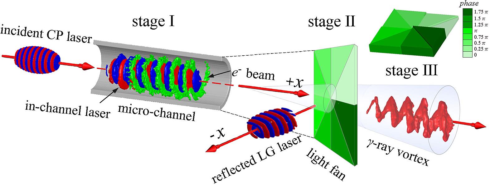
    Figure 1.Schematic of γ-ray vortex generation from a laser-illuminated light-fan-in-channel target. A CP laser pulse is incident from the left and irradiates a micro-channel target. Electrons are extracted from the channel wall, travel along the channel, and are accelerated to hundreds of MeV by the longitudinal electric fields. Later, the laser pulse is reflected along the – x axis by a light fan and an LG laser pulse is thus formed which collides head-on with the dense energetic electron beam with large AM. This finally results in the generation of a bright multi-MeV γ-ray vortex. Note that the fan-foil is perpendicular to the axis of the micro-channel and the arrow of reflected laser points to the micro-channel.

    2.2 Electron acceleration in the micro-channel

    Micro-channel targets have been widely employed to reshape the laser profile and enhance electron and ion acceleration[68,70,71]. They can act as a unique source of well-defined electron bunches and have potential applications in bright X/γ-photon emission. Assuming a CP plane wave in the form of $\mathbf{E}\left(x,y,z,t\right)=\mathbf{E}\left(x,y,z\right){e}^{i\left( kx-{\omega}_0t\right)}$, one can obtain ${\nabla}^2\mathbf{E}+{k}^2\mathbf{E}=0$ and $\nabla \cdot \mathbf{E}=0$ from Maxwell equations. If the wave propagates in the positive $x$ direction, the longitudinal electric field can be described by ${E}_x=i/k\left(\partial {E}_y/\partial y+\partial {E}_z/\partial z\right)$. For a Gaussian laser pulse in free space with ${\mathbf{E}}_{\perp }={E}_0\exp \left(-{r}^2/{\sigma}^2\right)\left[\cos \left( kx-{\omega}_0t\right){\widehat{\mathbf{e}}}_y+\sin \left( kx-{\omega}_0t\right){\widehat{\mathbf{e}}}_z\right]$, the longitudinal component of laser pulse is of the form

    $$\begin{align}{E}_x=\frac{2{E}_0}{k{\sigma}^2}\exp \left(\frac{-{r}^2}{\sigma^2}\right)\left[\sin \left( kx-{\omega}_0t\right)y-\cos \left( kx-{\omega}_0t\right)z\right],\end{align}$$ 

    which is obviously much smaller relative to the laser transverse electric field. As for the laser parameters used in our simulations, the amplitude of the longitudinal laser electric field is only about 0.03${E}_0$ based on Equation (1). However, when such a tightly focused Gaussian laser is injected into the micro-channel, the laser field distribution and propagation become quite different from that in vacuum. In this situation, the channel target acts as an optical waveguide, which is able to stimulate a series of high modes[71]. Although their transverse electric fields are relatively weaker than the incident Gaussian (LG${}_{00}$) mode as shown in Figure 2, they have much stronger longitudinal electric fields. Here, the longitudinal electric field in the plasma channel can be approximately written as[71]

    $$\begin{align*}{E}_x&\simeq {E}_0\frac{k_1{J}_{1,\max }}{k_x{J}_{x,\max}^{\prime }}\exp \left(-{r}_0^2/{\sigma}_0^2\right)\\&={E}_0\frac{1.164}{\sqrt{{\left(2\pi {r}_0/{v}_{1l}{\lambda}_0\right)}^2-1}}\exp \left(-{r}_0^2/{\sigma}_0^2\right),\end{align*}$$ 

    Distributions of the transverse electric field Ey at different cross-sections from to at . The black dots represent the positions of energetic electrons dragged out from the channel wall.

    Figure 2.Distributions of the transverse electric field Ey at different cross-sections from to at . The black dots represent the positions of energetic electrons dragged out from the channel wall.

    where ${J}_{1,\max }$ and ${J}_{x,\max}^{\prime }$ are the maximum values of the first-order Bessel function of the first kind and its derivative with respect to r, respectively, and ${v}_{1l}$ is the lth root of the first-order Bessel function. As shown in Figures 3(b) and 3(c), the cross-section of the longitudinal electric field has higher mode which is in accord with the previous similar simulation[71]. The maximum dimensionless field amplitude of ${E}_x$ (${E}_x=20.45$) is nearly half of the maximum of ${E}_y$ (${E}_y=42.47$), which is close to the theoretical result as for the parameters used in our simulations, ${E}_x\simeq 0.78{E}_0$. Such a strong longitudinal electric field which is increased significantly as compared with that in vacuum is capable of accelerating electrons to high energies.

    (a) Three-dimensional isosurface distribution of electron energy density of 60 MeV at . The (y, z) projection plane of electron energy density on the left is taken at , the (x, y) projection plane at the bottom is taken at z = 0, and the (x, z) projection plane at the rear is taken at y = 0. Distribution of the (b) longitudinal electric field Ex and (c) transverse electric field Ey at and . (d) Typical electron trajectories in the phase space (). (e) Projection of some typical electron trajectories in the y–z plane until . Here the colorbar represents the electron energy. (f) Electron momentum distribution in the y–z plane at . Evolution of (g) electron beam divergence and (h) energy spectrum. The black dashed circles in (d)–(f) represent the boundaries of the micro-channel.

    Figure 3.(a) Three-dimensional isosurface distribution of electron energy density of 60 MeV at . The (y, z) projection plane of electron energy density on the left is taken at , the (x, y) projection plane at the bottom is taken at z = 0, and the (x, z) projection plane at the rear is taken at y = 0. Distribution of the (b) longitudinal electric field Ex and (c) transverse electric field Ey at and . (d) Typical electron trajectories in the phase space (). (e) Projection of some typical electron trajectories in the yz plane until . Here the colorbar represents the electron energy. (f) Electron momentum distribution in the yz plane at . Evolution of (g) electron beam divergence and (h) energy spectrum. The black dashed circles in (d)–(f) represent the boundaries of the micro-channel.

    Figure 2 presents the transverse electric field Ey and electron distribution in the yz plane ranging from $x=11{\lambda}_0$ to $12{\lambda}_0$ at $t=16{T}_0$. One sees that these electrons are well directed along the channel walls. At a single laser wavelength, e.g., $x=11{\lambda}_0$$12{\lambda}_0$, these electrons located at different positions have different but regular spatial distribution, which is in excellent agreement with the laser transverse electric field. This indicates that these electrons are pulled out from the channel wall by the laser transverse electric field. They form a helical bunch as shown in Figure 3(a), with phase interval of $\pi$ between upper and lower parts, which results from the helical structure of the laser electric field.

    In order to investigate the electron acceleration inside the micro-channel, we track some typical electrons (energy above 100 MeV at $t=16{T}_0$) in the simulations and record their positions and characteristics of the field experienced by the electrons. For clarity, we furthermore separate the electron energy gain into two parts, ${\eta}_x=-{q}_e{\int}_0^t{v}_x{E}_x\mathrm{d}t/{m}_{e0}{c}^2$, ${\eta}_{\perp }=-{q}_e{\int}_0^t\left({v}_y{E}_y+{v}_z{E}_z\right)\mathrm{d}t/{m}_{e0}{c}^2$. Here, ${\eta}_x$ is the energy gain by the longitudinal electric field, ${\eta}_{\perp }$ is the energy gain by the transverse field, and the electron energy $\gamma (t)=\gamma (0)+{\eta}_x+{\eta}_{\perp }$. The trajectories of the traced electrons in the phase space (${\eta}_x$, ${\eta}_{\perp }$) are shown in Figure 3(d). One can see that most of the electron acceleration is dominated by the longitudinal electric fields and the contribution of the transverse electric field to the electron acceleration is very limited. Figure 3(e) presents the projection of some typical electron trajectories in the y-z plane until $t=30{T}_0$ and Figure 3(f) shows the corresponding momenta at $t=20{T}_0$. Once the electrons are pulled out from the channel inner wall, they move forward around the laser axis. When the electrons enter into an applicable laser phase, they gain steady acceleration. However, the electron trajectories do not exactly point to the laser axis as indicated by Figure 3(e), but have a small deviation initially, implying a large OAM for each electron. This can be also seen from Figure 3(f), where the motion of most of the electrons is counterclockwise. The collective motion of these electrons in the micro-channel results in the formation of an energetic electron beam with large AM. Figures 3(g) and 3(h) present the evolution of the electron divergence with energy above 1 MeV and the corresponding electron energy spectra at $t=8{T}_0$, $16{T}_0$, $24{T}_0$, and $30{T}_0$. In this stage the electron beam is well directed along the micro-channel wall and is distinctive with a small divergence angle of approximately 5.7°, a cutoff energy of 240 MeV, and nC charges at $t=16{T}_0$. After that, the electrons are characterized by $4\pi$ radian in space and the cutoff energy drops rapidly at $t=30{T}_0$, indicating the commencement of the second stage.

    2.3 Laser pulse reflection by the light fan

    As the laser pulse propagates in the channel and arrives at the fan-foil attached to the channel, the second stage starts. Here, the thickness of the fan-foil increases with the angle ϕ in the cylindrical coordinate system, as illustrated in Figure 1. When the laser irradiates the fan-foil, the reflected laser wave at different angle ϕ has different phase change, resulting in an LG pulse generation. LG laser can carry OAM, which can improve the BAM of γ-ray and the conversion efficiency of laser- γ-ray AM. We will discuss this point later. Figure 4 shows the laser transverse electric field Ey in the y-z plane at different positions between $x=10{\lambda}_0$ and $11{\lambda}_0$ at $t=26{T}_0$ when the incident laser pulse is completely reflected. As expected, the fan-foil behaves like a light fan, which changes the pulse wavefront and intensity distribution in space and results in the formation of an LG vortex. For simplicity, we assume a perfect fan mirror. Thus, the laser mode of the reflected pulse can be expanded by a series of LG modes[72]. The amplitude of the LGnm laser intensity can be defined in the cylindrical coordinate system ($\rho, \phi, x$) by

    $${\displaystyle \begin{array}{c}{\mathrm{L}\mathrm{G}}_{nm}\left(\rho, \phi, x\right)=\left({C}_{nm}/w\right)\exp \left(- ik{\rho}^2/2R\right)\exp \left(-{\rho}^2/{w}^2\right)\\ {}\kern1.5em \times \kern0.5em \exp \left[-i\left(n+m+1\right)\psi \right]\\ {}\quad\qquad\kern1.5em \times \kern0.5em \exp \left[-i\left(n-m\right)\phi \right]{\left(-1\right)}^{\min \left(n,m\right)}\\ {}\qquad\qquad\kern2.5em \times \kern0.5em {\left(\rho \sqrt{2}/w\right)}^{\mid n-m\mid }{L}_{\min \left(n,m\right)}^{\mid n-m\mid}\left(2{\rho}^2/{w}^2\right),\end{array}}$$ 

    Distributions of the transverse electric field Ey at different cross-sections from to at when the incident laser pulse is completely reflected by the light fan.

    Figure 4.Distributions of the transverse electric field Ey at different cross-sections from to at when the incident laser pulse is completely reflected by the light fan.

    where $R(x)=\left({x}_R^2+{x}^2\right)/x$, $w(x)={\left[2\left({x}_R^2+{x}^2\right)/{kx}_R\right]}^{1/2}$, $\psi (x)=\arctan \left(x/{x}_R\right)$, Cnm is a normalization constant, $k=2\pi /\lambda$ is the wave number, ${x}_R$ is the Rayleigh range, ${L}_{\min \left(n,m\right)}^{\mid n-m\mid }(x)$ is the generalized Laguerre polynomial, and $l=\kern0.5em \mid n-m\mid$ is the azimuthal mode index. For a laser pulse with helical phase front and an exp(ilϕ) azimuthal phase dependence, the OAM along the laser propagating direction has a discrete value of $l\mathit{\hslash}$ per photon. Although the incident laser can stimulate a series of high modes in the channel, the dominant laser mode upon the fan-foil is still the former LG00 as shown in Figure 2. Thus, mode decomposition of incident LG00 mode whose wave front has been modified by the light fan structure can be written using the expansion coefficients[72]

    $$\begin{align}{{a}}_{st}&=\left\langle {\mathrm{L}\mathrm{G}}_{st}|\exp \left(- i\Delta \phi \right)|{\mathrm{L}\mathrm{G}}_{00}\right\rangle \nonumber \\[-2pt] &=\iint \rho \mathrm{d}\rho \mathrm{d}\phi \left({C}_{st}^{\ast }/{w}_{st}\right)\exp \left( ik{\rho}^2/2{R}_{st}-{\rho}^2/{w}_{st}^2\right) \nonumber \\[-2pt] &\quad\times \kern0.5em \exp \left[i\left(s-t\right)\phi \right]{\left(-1\right)}^{\min \left(s,t\right)}{\left(\rho \sqrt{2}/{w}_{st}\right)}^{\mid s-t\mid} \nonumber \\[-2pt] &\quad\times \kern0.5em {{L}}_{\min \left(s,t\right)}^{\mid s-t\mid}\left(2{\rho}^2/{w}_{st}^2\right)\exp \left(- i\Delta \phi \right)\nonumber \\[-2pt] &\quad\times \kern0.5em \left({C}_{00}/w\right)\exp \left(- i k{\rho}^2/2R-{\rho}^2/{w}^2\right). \end{align}$$ 

    Here $\Delta \phi ={\sum}_{n=0}^7H\left(\phi -\pi /4n\right)H\left(\pi /4n+\pi /4-\phi \right)2\pi /8n$ and $H(x)$ is the Heaviside function. The mode thus becomes complicated and the percentage of the modes is given by ${I}_{st}={\left|{a}_{st}\right|}^2$. As $\Delta \phi \approx \phi$ as we settle in our simulations, only the modes with $l=s-t=1$ contribute most in the ϕ integral. Our calculations show that ${I}_{10}\approx 78.5\%$, so the dominant mode of the reflected laser pulse should be LG10[72], which is in excellent agreement with the simulation results as shown in Figure 4.

    2.4 Bright γ-ray vortex emission

    At the third stage, the reflected LG laser pulse collides head-on with the energetic electrons with large AM. Here, the stochastic emission model is employed and implemented in the EPOCH code using a probabilistic Monte Carlo algorithm. The QED emission rates are determined by the Lorentz-invariant parameter[73]: ${\chi}_e=e\mathrm{\hslash}\left({m}_e^3{c}^4\right)\mid {F}_{\mu \nu}{P}^{\nu}\mid$, where ${F}_{\mu \nu}$ is the electromagnetic field tensor and ${P}^{\nu }$ is the electron four-momentum. In our configuration, ${\chi}_e$ can be expressed by . Here, ${E}_s=\left({m}_e^2{c}^3\right)/ e\mathit{\hslash}$ denotes the Schwinger electric field, is the normalized velocity of electron by the speed of light in vacuum, ${\gamma}_e$ represents the electron relativistic factor, and E and B are the electromagnetic fields. In fact, the electron trajectories deflect once the electrons collide head-on with the reflected laser pulse, agreeing well with the analysis above. As the energetic electrons counter-propagate with the reflected LG pulse, the photon emission probabilities are increased significantly and ${\chi}_e$ can be described approximately by ${\chi}_e=2{\gamma}_e\mid {E}_{\perp}\mid /{E}_s$. Figure 5(a) illustrates the spatial distribution of ${\chi}_e$ along the $x$-axis at $t=22{T}_0$. Here ${\chi}_e$ is up to 0.55, implying efficient $\unicode{x3b3}$-photon emission.

    (a) Distributions of along the x-axis at and (b) three-dimensional isosurface distribution of photon number density of 10 nc at . The (y, z) projection plane on the left is taken at , the (x, y) projection plane at the bottom is taken at , and the (x, y) projection plane at the rear is taken at y = 0. (c)–(f) and (g)–(j) Transverse distributions of and the photon number density at different cross-sections ranging from to at The black dashed circles in (c)–(j) represent the boundaries of the micro-channel.

    Figure 5.(a) Distributions of along the x-axis at and (b) three-dimensional isosurface distribution of photon number density of 10 nc at . The (y, z) projection plane on the left is taken at , the (x, y) projection plane at the bottom is taken at , and the (x, y) projection plane at the rear is taken at y = 0. (c)–(f) and (g)–(j) Transverse distributions of and the photon number density at different cross-sections ranging from to at The black dashed circles in (c)–(j) represent the boundaries of the micro-channel.

    Figure 5(b) shows the 3D isosurface distribution of the number density of emitted $\unicode{x3b3}$-photons at $t=20{T}_0$. It is seen that the $\unicode{x3b3}$-photon beam is distinctive with a typical vortex structure in space, with few photons along the laser propagation axis. The maximum photon density is several tens of ${n}_c$. This indicates that the $\unicode{x3b3}$-rays are also LG-like, carrying AM. We will discuss this point later. In order to certify the formation of $\unicode{x3b3}$-ray, Figures 5(c)–5(f) and 5(g)–5(j) illustrate the transverse distribution of ${\chi}_e$ and the photon number density at different cross-sections ranging from $x=14.8{\lambda}_0$ to $15.4{\lambda}_0$ at $t=26{T}_0$. As expected, the larger the parameter ${\chi}_e$, the greater the $\unicode{x3b3}$-photon emission becomes. Meanwhile, the distribution of the $\unicode{x3b3}$-photons matches well with the energetic electrons as seen in Figure 2, confirming a photon beam with vortex structure in the micro-channel.

    Figure 6(a) presents the evolution of energy spectra of the $\unicode{x3b3}$-photons. As ${\chi}_e$ is as high as 0.55, the photon energy estimated by[74] $\,\mathit{\hslash \omega}\approx 0.44{\chi}_e{\unicode{x3b3}}_e{m}_e{c}^2$ in a head-on collision is approximately 76 MeV, which is consistent with the simulation results. Figure 6(b) displays the evolution of $\unicode{x3b3}$-photon brilliance (black line), instantaneous radiation power (red line), photon number (blue line), and total photon energy (green line). The photon emission occurs since $t=16{T}_0$ when the head-on collision takes place. The peak instantaneous radiation power is at $t=22{T}_0$. Here the power of radiation emitted by a single electron can be written as ${P}_{\mathrm{rad}}\approx 2e{E}_sc{\alpha}_f{\chi_e}^2g\left({\chi}_e\right)/3$, where ${\alpha}_f$ is the fine-structure constant, $g\left({\chi}_e\right)=\left[3\sqrt{3}/\left(2{\pi \chi}_e^2\right)\right]{\int}_0^{\infty }F\left({\chi}_e,{\chi}_{\unicode{x3b3}}\right)\textrm{d}{\chi}_{\unicode{x3b3} }$ is the radiation correction induced by the QED effect, and ${\chi}_{\unicode{x3b3} }=\left(\mathit{\hslash \omega }/2{m}_e{c}^2{E}_s\right)\sqrt{{\left(\textbf{E}+\textbf{k}\times \textbf{B}\right)}^2-{\left(\textbf{k}\cdot \textbf{E}\right)}^2}$ is another key quantum parameter determining the positron generation[73,75]. For simplicity, we take[76]$\,g\left({\chi}_e\right)=\big(3.7{\chi}_e^3+31{\chi}_e^2$$+12{\chi}_e+1\big){}^{-4/9}$, and thus the estimated radiation power with photon energy above 0.1 MeV is approximately 5 TW, which is in reasonable agreement with our PIC simulations of averaged radiation power of 6 TW. Meanwhile, the photon brilliance reached the maximum at around $t=23{T}_0$. After the collision, the photon number still increases, but the photon energy tends to be unchanged. This indicates that the major $\unicode{x3b3}$-photon emission results from the NCS process during the collision process. Figure 6(c) shows the divergence angle of $\unicode{x3b3}$-photons (top) with photon energy $\ge 0.1$ MeV, indicating a well-directed photon beam with a small divergence angle of approximately 9°. Conservatively, we consider a $\unicode{x3b3}$-photon vortex with yield of ${10}^{10}$ at 1 MeV, full width at half maximum duration of approximately 6.6 fs, source size of around $3\;\unicode{x3bc} {\mathrm{m}}^2$, and divergence of $160\ \textrm{mrad}\times 160$ mrad. This results in a $\unicode{x3b3}$-photon vortex source with peak brilliance of approximately $1{0}^{22}$ photons·s–1·mm–2·mrad–2 per 0.1% bandwidth at 1 MeV, peak instantaneous radiation power of 25 TW, averaged BAM of $1{0}^6\hslash$ /photon, and pulse energy of approximately 0.5 J. The peak intensity of the $\unicode{x3b3}$-rays is around ${10}^{20}$ W/cm${}^2$.

    (a) Energy spectra of γ-photons at , , , and . (b) Evolution of the γ-photon brilliance (black), instantaneous radiation power (red), photon number (blue), and total energy (green). Here the gray area marks the collision stage. (c) Divergence angle of γ-photons (top) at , , , and . Here the bottom shows the angular-energy distribution of -photons at .

    Figure 6.(a) Energy spectra of γ-photons at , , , and . (b) Evolution of the γ-photon brilliance (black), instantaneous radiation power (red), photon number (blue), and total energy (green). Here the gray area marks the collision stage. (c) Divergence angle of γ-photons (top) at , , , and . Here the bottom shows the angular-energy distribution of -photons at .

    2.5 AM transfer from laser to$\ \gamma$-photons

    Exploring the laser AM transfer to charged particles and photons is of significance for understanding the dynamics of laser–plasma interaction at high laser intensity. When a laser beam carrying nonzero AM impinges on plasma, its AM can be transferred to plasma ions and electrons, thus setting them in rotational motion. This occurs both with SAM and OAM. As we know, each photon carries $\hslash$ or –$\hslash$ SAM. To get a powerful AM source, we use an ultra-intense CP Gaussian laser in our scheme. Once the intense CP laser pulse interacts with a micro-channel target, its SAM can be transferred to electrons and ions, and finally to the $\unicode{x3b3}$-photons via the NCS process. Here, the total AM of the incident CP laser pulse can be calculated exactly by

    $$\begin{align}{\textbf{L}}_{\mathrm{laser}}={\varepsilon}_0\int \textbf{r}\times \left(\textbf{E}\times \textbf{B}\right)\mathrm{d}v,\end{align}$$ 

    where $\mathbf{r}$ is the grid’s position, and $\mathbf{E}$ and $\mathbf{B}$ are the corresponding electromagnetic fields in each grid. The BAM of particles with respect to the laser axis is defined by

    $${\mathbf{L}}_{e,C,H,\unicode{x3b3} }=\sum \limits_i\left({\mathbf{r}}_i\times {\mathbf{p}}_i\right).$$ 

    Here the subscript i denotes the serial number of individual particles. The photons’ momentum originates from the parent electrons, the averaged momentum can be scaled as[77]${\ \overline{p}}_{\unicode{x3b3}}\propto {\chi}_e^2g\left({\chi}_e\right)$. One can thus estimate the photon AM as ${L}_{\unicode{x3b3}}\propto {N}_{\unicode{x3b3} }{\overline{r}}_{\unicode{x3b3} }{\overline{p}}_{\unicode{x3b3}}\propto {N}_{\unicode{x3b3} }{\overline{r}}_{\unicode{x3b3} }{\chi}_e^2g\left({\chi}_e\right)$, where ${N}_{\unicode{x3b3} }$ and ${\overline{r}}_{\unicode{x3b3} }$ are the yield and the average off-axis radius of photons. Figures 7(a) and 7(b) show the evolution of the particles’ BAM and the laser energy conversion efficiency to charge particles and $\unicode{x3b3}$-photons. At the first stage, the CP laser pulse accelerates the electrons in the micro-channel and transfers its SAM to the energetic electrons, so that the electrons’ BAM and energy increase. At the second stage, the light fan modifies the wave front by adding exp(ilϕ) to the phase of the drive. Thus, the electron BAM increases more sharply during the collision stage, because the reflected pulse is also able to transfer its AM to the electrons via the NCS process[52]. However, due to the photon emission and radiation reaction effect, the total energy of electrons keeps unchanged until the collision stage is completed. During the process, the carbon ions and protons occupy only very small AM as compared with the electrons. The final laser energy conversion efficiencies to electrons and photons are around 20% and 1.2%, respectively. We define the laser AM conversion efficiency to the $\unicode{x3b3}$-photons as ${\rho}_{\mathrm{AM}}=\frac{\sum_{i,\unicode{x3b3}}\mid {\textbf{r}}_{i,\unicode{x3b3}}\times {\textbf{p}}_{i,\unicode{x3b3}}\mid }{\mid {\varepsilon}_0\int \textbf{r}\times \left(\textbf{E}\times \textbf{B}\right)\mathrm{d}v\mid }$. Owing to the collective effect of the high-energy $\unicode{x3b3}$-photons emitted in the micro-channel, we summarize AM of all these photons and divide it by the total laser AM. The AM conversion efficiency from laser to $\unicode{x3b3}$-photons is unprecedentedly 0.67$\%$, which is nearly seven times higher than that of the scheme in Ref. [78]. Such an efficient multi-MeV $\unicode{x3b3}$-photon vortex source would offer exciting potential capabilities and opportunities for diverse studies, such as the investigation of the AM transfer by Kerr black holes[23,24]. For example, it may be common in the universe to generate vortex photons by high-energy electrons interacting with CP electromagnetic waves. These phenomena tend to be found easily in some astrophysical environments, e.g., in the vicinity of magnetized near neutron stars and in turbulent plasma in astrophysical jets, which have attracted the attention of numerous researchers[23,24,27,57]. Our scheme shows a possible way to study the photon vortex generation in the universe by laser–plasma interactions.

    (a) Evolution of BAM of electrons (black arrow), protons (blue arrow), carbon ions (green arrow), and -photons (red arrow). (b) Evolution of laser energy conversion efficiency to electrons (black arrow), protons (blue arrow), carbon ions (green arrow), and -protons (red arrow). Here the gray area denotes the collision stage and the arrows indicate the y axes of different curves.

    Figure 7.(a) Evolution of BAM of electrons (black arrow), protons (blue arrow), carbon ions (green arrow), and -photons (red arrow). (b) Evolution of laser energy conversion efficiency to electrons (black arrow), protons (blue arrow), carbon ions (green arrow), and -protons (red arrow). Here the gray area denotes the collision stage and the arrows indicate the y axes of different curves.

    3 Discussion

    In order to demonstrate that the light fan is capable of increasing the laser photon’s AM, a plane foil and a right-hand helix foil (RH fan) are considered separately in our additional PIC simulations. The differences can be easily distinguished from each photon’s AM during the laser–foil interaction. For a laser pulse, its total electromagnetic energy is $\frac{1}{2}\int \big({\varepsilon}_0{E}^2+\frac{1}{\mu_0}{B}^2\big)\mathrm{d}v$, where ${\mu}_0$ is the vacuum permeability. Therefore, each photon’s averaged AM can be written as

    $$\begin{align}{L}_{\mathrm{photon}}&=\frac{\varepsilon_0\int \textbf{r}\times \left(\textbf{E}\times \textbf{B}\right)\mathrm{d}v}{\frac{1}{2}\int \left({\varepsilon}_0{\textbf{E}}^2+\frac{1}{\mu_0}{\textbf{B}}^2\right)\mathrm{d}v}\hslash {\omega}_0, \nonumber \\ &=\left(\delta +l\right)\hslash, \end{align}$$ 

    where $\delta$ and $l$ represent the SAM and OAM quantum number of a photon, respectively, and $\hslash {\omega}_0$ is the laser photon energy. For a left-handed CP Gaussian pulse considered in our simulations, each photon has an AM of ${L}_{\mathrm{photon}}=\left(-1+0\right)\hslash =-\hslash$. Figure 8(a) shows the evolution of the laser photon averaged AM. At the first stage, the averaged AM of the laser photons is exactly $-\hslash$, which indicates that the left-handed CP LG00 mode is still dominant and the laser pulse is well kept in the micro-channel. This is consistent with the analysis above. Once the interaction enters into the second stage, the averaged AM of each photon increases up to –1.6$\hslash$ for an LH fan. By contrast, it is nearly unchanged for a plane foil and is about –0.6$\hslash$ for an RH fan. This implies that the light fan can adjust efficiently the laser AM by changing the wave front. It is also worth stressing that the AM of the protons and carbon ions in the foil will be also adjusted significantly by use of different fan-foil, which is beyond scope of the current work. Note that, when the fan-foil target is left-handed, the increased OAM of the left-handed CP laser is along the negative $x$ axis direction. Therefore, the AM absolute value of laser increases. When the fan-foil target is right-handed, the increased OAM of the laser is along the positive $x$ axis direction. The averaged AM value of laser photons decreases as shown in Figure 8(a). Thus, the AM absolute value of right-handed laser will decrease when it is reflected by the left-handed fan-foil target.

    Evolution of (a) averaged AM of laser photons and (b) averaged BAM of -photons in the right-handed helix fan case (RH fan, black), plane foil case (blue), and left-handed helix fan case (LF fan, red). The gray area shows the collision stage.

    Figure 8.Evolution of (a) averaged AM of laser photons and (b) averaged BAM of -photons in the right-handed helix fan case (RH fan, black), plane foil case (blue), and left-handed helix fan case (LF fan, red). The gray area shows the collision stage.

    Figure 8(b) illustrates the evolution of averaged BAM of $\unicode{x3b3}$-photon beams in all three cases. One can see that during the second stage the efficiency of $\unicode{x3b3}$-photon emission increases drastically due to the large ${\chi}_e$. Meanwhile, the laser AM is also transferred more efficiently to the $\unicode{x3b3}$-photons in the LH fan case, which is 16$\%$ higher than that in the plane case and RH fan case. When the foil is left-handed, the reflected laser pulse can increase the $\unicode{x3b3}$-photon’s averaged BAM, whereas the right-handed light foil will behave in an opposite manner. This results from the fact that the $\unicode{x3b3}$-photon beam’s averaged BAM originates from both the parent electrons and the reflected laser pulse. The latter is capable of increasing or decreasing the photon BAM, depending on the helix direction of the fan-foil and its step number. Once the head-on collision between the energetic electrons and reflected laser pulse terminates, the $\unicode{x3b3}$-photon BAM remains unchanged roughly.

    We also investigated the robustness of the scheme by using different laser and plasma parameters. First, we discuss the effect of the laser intensity, where we keep all other parameters unchanged but vary the normalized laser amplitude from ${a}_0=60$ to $140$. Figure 9 shows the scaling of the photon yield (${N}_{\unicode{x3b3} }$, black circles), the laser energy conversion efficiency (${\eta}_{\unicode{x3b3} }$, red circles), and photon BAM (${L}_{\unicode{x3b3} }$, blue circles) with the laser electric field amplitude ${a}_0$. It indicates that the $\unicode{x3b3}$-photon emission becomes more significant with the increase of laser intensity. For ${a}_0=140$, the photon yield and energy conversion efficiency can reach $6\times {10}^{12}$ and 2.5%, respectively. As the photon yield scales as ${N}_{\unicode{x3b3}}\propto {a}_0^3$ as shown in Figure 9(a), the BAM of the photon beams ${L}_{\unicode{x3b3}}\propto {N}_{\unicode{x3b3} }{\chi}_e^2g\left({\chi}_e\right)\propto {a}_0^{\sim 13/3}$, which is in excellent agreement with the results as shown in Figure 9(a).

    Scaling of the photon yield (, black circles), the laser energy conversion efficiency (, red circles), and total -photon BAM (, blue circles) with (a) the laser electric field amplitude and (b) the micro-channel length . Here, the black and blue curves are the fitting results.

    Figure 9.Scaling of the photon yield (, black circles), the laser energy conversion efficiency (, red circles), and total -photon BAM (, blue circles) with (a) the laser electric field amplitude and (b) the micro-channel length . Here, the black and blue curves are the fitting results.

    We also considered the effect of the length of micro-channel on the photon emission. Figure 9(b) shows the simulation results for which l is varied in the range of $10{\lambda}_0$ to $20{\lambda}_0$, with all other parameters unchanged. It shows that the photon yield and energy conversion efficiency are insensitive to the micro-channel length (within the range of lengths studied). However, the BAM scales as ${L}_{\unicode{x3b3}}\propto l$ as shown in Figure 9(b). This can be attributed to the relation ${\unicode{x3b3}}_e\propto e{\overline{E}}_xl$, which depends on the electron acceleration length. The BAM of photon beams can therefore be approximated by ${L}_{\unicode{x3b3}}\propto {N}_{\unicode{x3b3} }{\overline{r}}_{\unicode{x3b3} }{\overline{p}}_{\unicode{x3b3}}\propto {l}^{4/3}$, which is close to the simulation results in Figure 9(b). Our scheme thus provides a practical and efficient way to control the ultra-bright $\unicode{x3b3}$-photon vortex emission by designing the laser and target parameters, which could be tested in the upcoming laser facilities.

    4 Conclusion

    In conclusion, we have proposed and numerically demonstrated an all-optical laser–plasma scheme to produce multi-MeV $\unicode{x3b3}$-photon vortex in light-fan-in-channel target irradiated by high-power CP laser pulse with intensity of approximately $1{0}^{22}$ W/cm2. Full three-dimensional PIC simulations show that high brilliance ($\sim 1{0}^{22}$ photons·s–1·mm–2·mrad–2 per 0.1% bandwidth), large BAM ($\sim 1{0}^6\hslash$/photon), ultra-intense tens-of-TW and small divergence angle ($\sim {9}$°) $\unicode{x3b3}$-ray vortices can be efficiently achieved via the NCS process. With the upcoming multi-PW laser facilities such as ELI and SULF, this all-optical scheme not only provides a promising and practical avenue to generate bright $\unicode{x3b3}$-ray vortices for various applications such as laboratory astrophysics[27,57] and particle physics[79], but also enables future experimental tests of nonlinear QED theory in a new domain.

    References

    [1] Y. Eisen, A. Shor, I. Mardor. Nucl. Instrum. Methods Phys. Res. Sect. A Accel. Spectrom. Detect. Assoc. Equip., 428, 158(1999).

    [2] J. Ganz. Gamma Knife Neurosurgery(2011).

    [3] T. Brabec, F. Krausz. Rev. Modern Phys., 72, 545(2000).

    [4] S. V. Bulanov, T. Z. Esirkepov, M. Kando, J. Koga, K. Kondo, G. Korn. Plasma Phys. Rep., 41, 1(2015).

    [5] D. Habs, M. M. Günther, M. Jentschel, P. G. Thirolf. AIP Conf. Proc., 1462, 177(2012).

    [6] O. Renner, F. B. Rosmej. Matter Radiat. Extremes, 4, 024201(2019).

    [7] R. W. Schoenlein, W. P. Leemans, A. H. Chin, P. Volfbeyn, T. E. Glover, P. Balling, M. Zolotorev, K. J. Kim, S. Chattopadhyay, C. V. Shank. Astrophys. J., 274, 4(2003).

    [8] K. T. Phuoc, S. Corde, C. Thaury, V. Malka, A. Tafzi, J. P. Goddet, R. C. Shah, S. Sebban, A. Rousse. Nat. Photon., 6, 308(2012).

    [9] C. Yu, R. Qi, W. Wang, J. Liu, W. Li, C. Wang, Z. Zhang, J. Liu, Z. Qin, M. Fang, K. Feng, Y. Wu, Y. Tian, Y. Xu, F. Wu, Y. Leng, X. Weng, J. Wang, F. Wei, Y. Yi, Z. Song, R. Li, Z. Xu. Sci. Rep., 6, 29518(2016).

    [10] S. Cipiccia, M. R. Islam, B. Ersfeld, R. P. Shanks, E. Brunetti, G. Vieux, X. Yang, R. C. Issac, S. M. Wiggins, G. H. Welsh, M. P. Anania, D. Maneuski, R. Montgomery, G. Smith, M. Hoek, D. J. Hamilton, N. R.C. Lemos, D. Symes, P. P. Rajeev, V. O. Shea, J. M. Dias, D. A. Jaroszynski. Nat. Phys., 7, 867(2011).

    [11] N. D. Powers, I. Ghebregziabher, G. Golovin, C. Liu, S. Chen, S. Banerjee, J. Zhang, D. P. Umstadter. Nat. Photon., 8, 28(2014).

    [12] S. Chen, N. D. Powers, I. Ghebregziabher, C. M. Maharjan, C. Liu, G. Golovin, S. Banerjee, J. Zhang, N. Cunningham, A. Moorti, S. Clarke, S. Pozzi, D. P. Umstadter. Phys. Rev. Lett., 110, 155003(2013).

    [13] W. M. Wang, Z. M. Sheng, P. Gibbon, L. M. Chen, Y. T. Li, J. Zhang. Proc. Natl. Acad. Sci. USA, 115, 9911(2018).

    [14] X.-L. Zhu, M. Chen, T.-P. Yu, S.-M. Weng, F. He, Z.-M. Sheng. Matter Radiat. Extremes, 4, 014401(2019).

    [15] D. J. Stark, T. Toncian, A. V. Arefiev. Phys. Rev. Lett., 116, 185003(2016).

    [16] Y.-J. Gu, M. Jirka, O. Klimo, S. Weber. Matter Radiat. Extremes, 4, 064403(2019).

    [17] J. Wang, X. B. Li, L. F. Gan, Y. Xie, C. L. Zhong, C. T. Zhou, S. P. Zhu, X. T. He. Phys. Rev. Appl., 14, 014094(2020).

    [18] Y. Lu, G.-B. Zhang, J. Zhao, Y.-T. Hu, H. Zhang, D.-A. Li, Q.-N. Li, Y. Cao, Y.-B. Wu, Y. Yin, F.-Q. Shao, T.-P. Yu. Opt. Express, 29, 8926(2021).

    [19] T. P. Yu, A. Pukhov, Z. M. Sheng, F. Liu, G. Shvets. Phys. Rev. Lett., 110, 045001(2013).

    [20] T. P. Yu, L. X. Hu, Y. Yin, F. Q. Shao, H. B. Zhuo, Y. Y. Ma, X. H. Yang, W. Luo, A. Pukhov. Appl. Phys. Lett., 105, 114101(2014).

    [21] S. Fürhapter, A. Jesacher, S. Bernet, M. Ritsch-Marte. Opt. Express, 13, 689(2005).

    [22] M. F. Andersen, C. Ryu, P. Cladé, V. Natarajan, A. Vaziri, K. Helmerson, W. D. Phillips. Phys. Rev. Lett., 97, 170406(2006).

    [23] F. Tamburini, B. Thidé, G. Molina-Terriza, G. Anzolin. Nat. Phys., 7, 195(2011).

    [24] M. Harwit. Astrophys. J., 597, 1266(2003).

    [25] N. M. Elias. Astron. Astrophys., 492, 883(2008).

    [26] F. Tamburini, A. Sponselli, B. Thidé, J. T. Mendonça. EPL, 90, 1303(2010).

    [27] Y. Taira, M. Katoh. Astrophys. J., 860, 45(2018).

    [28] Y. Shi, B. Shen, L. Zhang, X. Zhang, W. Wang, Z. Xu. Phys. Rev. Lett., 112, 235001(2014).

    [29] W. Gong, B. Shen, L. Zhang, X. Zhang. New J. Phys., 21, 43022(2019).

    [30] J. Vieira, R. M. G. M. Trines, E. P. Alves, R. A. Fonseca, J. T. Mendonça, R. Bingham, P. Norreys, L. O. Silva. Nat. Commun., 7, 10371(2016).

    [31] G. Lehmann, K. H. Spatschek. Phys. Rev. Lett., 116, 225002(2016).

    [32] A. Leblanc, A. Denoeud, L. Chopineau, G. Mennerat, P. Martin, F. Quéré. Nat. Phys., 13, 440(2017).

    [33] X. Zhang, B. Shen, L. Zhang, J. Xu, X. Wang, W. Wang, L. Yi, Y. Shi. New J. Phys., 16, 123051(2014).

    [34] J. Vieira, J. T. Mendonça. Phys. Rev. Lett., 112, 215001(2014).

    [35] Y. Shi, J. Vieira, R. M. G. M. Trines, R. Bingham, B. F. Shen, R. J. Kingham. Phys. Rev. Lett., 121, 145002(2018).

    [36] C. Baumann, A. Pukhov. Phys. Plasmas, 25, 083114(2018).

    [37] L. X. Hu, T. P. Yu, H. Z. Li, Y. Yin, P. McKenna, F. Q. Shao. Opt. Lett., 43, 2615(2018).

    [38] L. X. Hu, T. P. Yu, Z. M. Sheng, J. Vieira, D. B. Zou, Y. Yin, P. McKenna, F. Q. Shao. Sci. Rep., 8, 7282(2018).

    [39] W. Wang, B. Shen, X. Zhang, L. Zhang, Y. Shi, Z. Xu. Sci. Rep., 5, 8274(2015).

    [40] G. B. Zhang, M. Chen, C. B. Schroeder, J. Luo, M. Zeng, F. Y. Li, L. L. Yu, S. M. Weng, Y. Y. Ma, T. P. Yu, Z. M. Sheng, E. Esarey. Phys. Plasmas, 23, 033114(2016).

    [41] G. B. Zhang, M. Chen, J. Luo, M. Zeng, T. Yuan, J. Y. Yu, Y. Y. Ma, T. P. Yu, L. L. Yu, S. M. Weng, Z. M. Sheng. J. Appl. Phys., 119, 103101(2016).

    [42] W. P. Wang, C. Jiang, B. F. Shen, F. Yuan, Z. M. Gan, H. Zhang, S. H. Zhai, Z. Z. Xu. Phys. Rev. Lett., 122, 024801(2019).

    [43] E. Hemsing, A. Marinelli. Phys. Rev. Lett., 109, 224801(2012).

    [44] E. Hemsing, A. Knyazik, M. Dunning, D. Xiang, A. Marinelli, C. Hast, J. B. Rosenzweig. Nat. Phys., 9, 549(2013).

    [45] X. Zhang, B. Shen, Y. Shi, X. Wang, L. Zhang, W. Wang, J. Xu, L. Yi, Z. Xu. Phys. Rev. Lett., 114, 173901(2015).

    [46] Y.-T. Hu, J. Zhao, H. Zhang, Y. Lu, W.-Q. Wang, L.-X. Hu, F.-Q. Shao, T.-P. Yu. Appl. Phys. Lett., 118, 054101(2021).

    [47] H. Zhang, G. B. Zhang, D. B. Zou, L. X. Hu, H. Y. Zhou, W. Q. Wang, X. R. Xu, K. Liu, Y. Yin, H. B. Zhuo, F. Q. Shao, T. P. Yu. Phys. Plasmas, 27, 053105(2020).

    [48] L. B. Ju, C. T. Zhou, K. Jiang, T. W. Huang, H. Zhang, T. X. Cai, J. M. Cao, B. Qiao, S. C. Ruan. New J. Phys., 20, 063004(2018).

    [49] Y.-Y. Chen, K. Z. Hatsagortsyan, C. H. Keitel. Matter Radiat. Extremes, 4, 024401(2019).

    [50] J. W. Wang, M. Zepf, S. G. Rykovanov. Nat. Commun., 10, 5554(2019).

    [51] W. P. Wang, C. Jiang, H. Dong, X. M. Lu, Z. Z. Xu. Phys. Rev. Lett., 125, 034801(2020).

    [52] X. L. Zhu, T. P. Yu, M. Chen, S. M. Weng, Z. M. Sheng. New J. Phys., 20, 83013(2018).

    [53] L. B. Ju, C. T. Zhou, T. W. Huang, K. Jiang, C. N. Wu, T. Y. Long, L. Li, H. Zhang, M. Y. Yu, S. C. Ruan. Phys. Rev. Appl., 12, 014054(2019).

    [54] C. Liu, B. Shen, X. Zhang, Y. Shi, L. Ji, W. Wang, L. Yi, L. Zhang, T. Xu, Z. Pei, Z. Xu. Phys. Plasmas, 23, 093120(2016).

    [55] Y. Y. Liu, Y. I. Salamin, Z. K. Dou, Z. F. Xu, J. X. Li. Opt. Lett., 45, 395(2020).

    [56] Y. Y. Chen, J. X. Li, K. Z. Hatsagortsyan, C. H. Keitel. Phys. Rev. Lett., 121, 74801(2018).

    [57] M. Katoh, M. Fujimoto, H. Kawaguchi, K. Tsuchiya, K. Ohmi, T. Kaneyasu, Y. Taira, M. Hosaka, A. Mochihashi, Y. Takashima. Phys. Rev. Lett., 118, 094801(2017).

    [58] V. Petrillo, G. Dattoli, I. Drebot, F. Nguyen. Phys. Rev. Lett., 117, 123903(2016).

    [59] U. D. Jentschura, V. G. Serbo. Phys. Rev. Lett., 106, 013001(2011).

    [60] B. King, N. Elkina, H. Ruhl. Phys. Rev. A, 87, 042117(2013).

    [61] D. D. Sorbo, D. Seipt, T. G. Blackburn, A. G. R. Thomas, C. D. Murphy, J. G. Kirk, C. P. Ridgers. Phys. Rev. A, 96, 043407(2017).

    [62] G. A. Mourou, G. Korn, W. Sandner, J. L. Collier. ELI - Extreme Light Infrastructure White Book(2011).

    [63] D. N. Papadopoulos, J. P. Zou, C. L. Blanc, G. Chériaux, P. Georges, F. Druon, G. Mennerat, P. Ramirez, L. Martin, A. Fréneaux, A. Beluze, N. Lebas, P. Monot, F. Mathieu, P. Audebert. High Power Laser Sci. Eng, 4(2016).

    [64] W. Li, Z. Gan, L. Yu, C. Wang, Y. Liu, Z. Guo, L. Xu, M. Xu, Y. Hang, Y. Xu, J. Wang, P. Huang, H. Cao, B. Yao, X. Zhang, L. Chen, Y. Tang, S. Li, X. Liu, S. Li, M. He, D. Yin, X. Liang, Y. Leng, R. Li, Z. Xu. Opt. Lett., 43, 5681(2018).

    [65] G. Doumy, F. Quéré, O. Gobert, M. Perdrix, P. Martin, P. Audebert, J. C. Gauthier, J.-P. Geindre, T. Wittmann. Phys. Rev. E, 69, 026402(2004).

    [66] A Lévy, T. Ceccotti, P. D’Oliveira, F. Réau, M. Perdrix, F. Quéré, P. Monot, M. Bougeard, H. Lagadec, P. Martin, J.-P. Geindre, P. Audebert. Opt. Lett., 32, 310(2007).

    [67] B. Dromey, S. Kar, M. Zepf, P. Foster. Rev. Sci. Instrum., 75, 645(2004).

    [68] J. Snyder, L. L. Ji, K. M. George, C. Willis, G. E. Cochran, R. L. Daskalova, A. Handler, T. Rubin, P. L. Poole, D. Nasir, A. Zingale, E. Chowdhury, B. F. Shen, D. W. Schumacher. Phys. Plasmas, 26, 033110(2019).

    [69] M. A. Purvis, V. N. Shlyaptsev, R. Hollinger, C. Bargsten, A. Pukhov, A. Prieto, Y. Wang, B. M. Luther, L. Yin, S. Wang, J. J. Rocca. Nat. Photon., 7, 796(2013).

    [70] K. D. Xiao, T. W. Huang, L. B. Ju, R. Li, S. L. Yang, Y. C. Yang, S. Z. Wu, H. Zhang, B. Qiao, S. C. Ruan, C. T. Zhou, X. T. He. Phys. Rev. E, 93, 043207(2016).

    [71] D. Y. Yu, D. B. Zou, M. Y. Yu, T. P. Yu, Y. Yin, F. Q. Shao, H. B. Zhuo, C. T. Zhou, S. C. Ruan. New J. Phys., 21, 083003(2019).

    [72] M. W. Beijersbergen, R. P. C. Coerwinkel, M. Kristensen, J. P. Woerdman. Opt. Angular Moment., 112, 179(2016).

    [73] V. I. Ritus. Quantum Effects of the Interaction of Elementary Particles with an Intense Electromagnetic Field(1985).

    [74] A. R. Bell, J. G. Kirk. Phys. Rev. Lett., 101, 200403(2008).

    [75] J. G. Kirk, A. R. Bell, I. Arka. Plasma Phys. Control. Fusion, 51, 085008(2009).

    [76] M. J. Duff, R. Capdessus, D. Del Sorbo, C. P. Ridgers, M. King, P. McKenna. Plasma Phys. Control. Fusion, 60, 064006(2018).

    [77] X. L. Zhu, M. Chen, T. P. Yu, S. M. Weng, L. X. Hu, P. McKenna, Z. M. Sheng. Appl. Phys. Lett., 112, 174102(2018).

    [78] B. Feng, C. Y. Qin, X. S. Geng, Q. Yu, W. Q. Wang, Y. T. Wu, X. Yan, L. L. Ji, B. F. Shen. Sci. Rep., 9, 18780(2019).

    [79] I. P. Ivanov. Phys. Rev. D, 83, 093001(2011).

    Hao Zhang, Jie Zhao, Yanting Hu, Qianni Li, Yu Lu, Yue Cao, Debin Zou, Zhengming Sheng, Francesco Pegoraro, Paul McKenna, Fuqiu Shao, Tongpu Yu. Efficient bright γ-ray vortex emission from a laser-illuminated light-fan-in-channel target[J]. High Power Laser Science and Engineering, 2021, 9(3): 03000e43
    Download Citation