
Zhilan Lu, Chao Shen, Jianyang Shi, Nan Chi. Security enhanced underwater visible light communication system based on chaotic phase scrambling and conjugate frequency hopping[J]. Chinese Optics Letters, 2023, 21(6): 060602
- Chinese Optics Letters
- Vol. 21, Issue 6, 060602 (2023)
Abstract
Keywords
1. Introduction
Underwater visible light communication (UVLC) has a high research value in the development and utilization of new spectrum resources due to such excellent properties as having no available bandwidth limitation, having high speed and high capacity, being far from traditional radio frequency bands, and abundant spectrum resources. In terms of security performance, optical fiber communication is wired communication that is theoretically a secure communication, where the signal is always transmitted in the cable. Wireless communication systems such as VLC have the risk of being eavesdropped because the signal is transmitted without passing through cables. However, compared with traditional radio frequency communication, VLC has a higher transmission frequency, a shorter wavelength, and cannot penetrate the wall. VLC has a high security performance[1–6], but it still cannot avoid the situation where the signal is stolen by eavesdroppers in the same space[7,8]. Therefore, it is necessary to study the signal encryption technology applicable to UVLC systems to improve the security of transmission.
In 2018, Fudan University proposed the first spectral scrambling security strategy for UVLC systems in the physical layer[9], but by analyzing the spectral characteristics of the signal, this encryption can potentially be broken at the receiver side. Therefore, it is necessary to use multidimensional encryption techniques to protect the transmission signals. In 2021, Zhejiang University first verified the feasibility of chaotic encryption in high-speed UVLC systems[10], using two-dimensional encryption at the bit and subcarrier levels and verified that chaotic encryption has no negative impact on the performance of the system. In 2022, they also used bitstream diffusion, in-phase and quadrature components scrambling, and time and frequency scrambling for three-dimensional encryption of UVLC systems[11]. However, all these encryption algorithms are complex in implementation and have high requirements for system performance.
In this paper, we propose a two-dimensional encryption technique based on chaotic phase scrambling and conjugate frequency hopping to encrypt the spectrum of PAM-8 signals and drive a blue LED for transmission in a 1.2 m water tank. At the receiver side, the PAM-8 signal is synchronized by correlating the received signal with the original transmitted signal, and then it is filtered by the least-mean-square (LMS) algorithm and Volterra filter. With the codebook at the transmitter side, we remove the conjugate frequency hopping encryption, the phase scrambling encryption, and finally, the symbol information is mapped back to the bit sequence for BER testing. A maximum transmission rate of 2.1 Gbit/s was experimentally measured with a BER below 7% the hard-decision forward error correction (HD-FEC) threshold. The complexity and security of the system are also analyzed and discussed in this paper, confirming its feasibility and high transmission reliability for physical implementation.
Sign up for Chinese Optics Letters TOC. Get the latest issue of Chinese Optics Letters delivered right to you!Sign up now
2. Principle
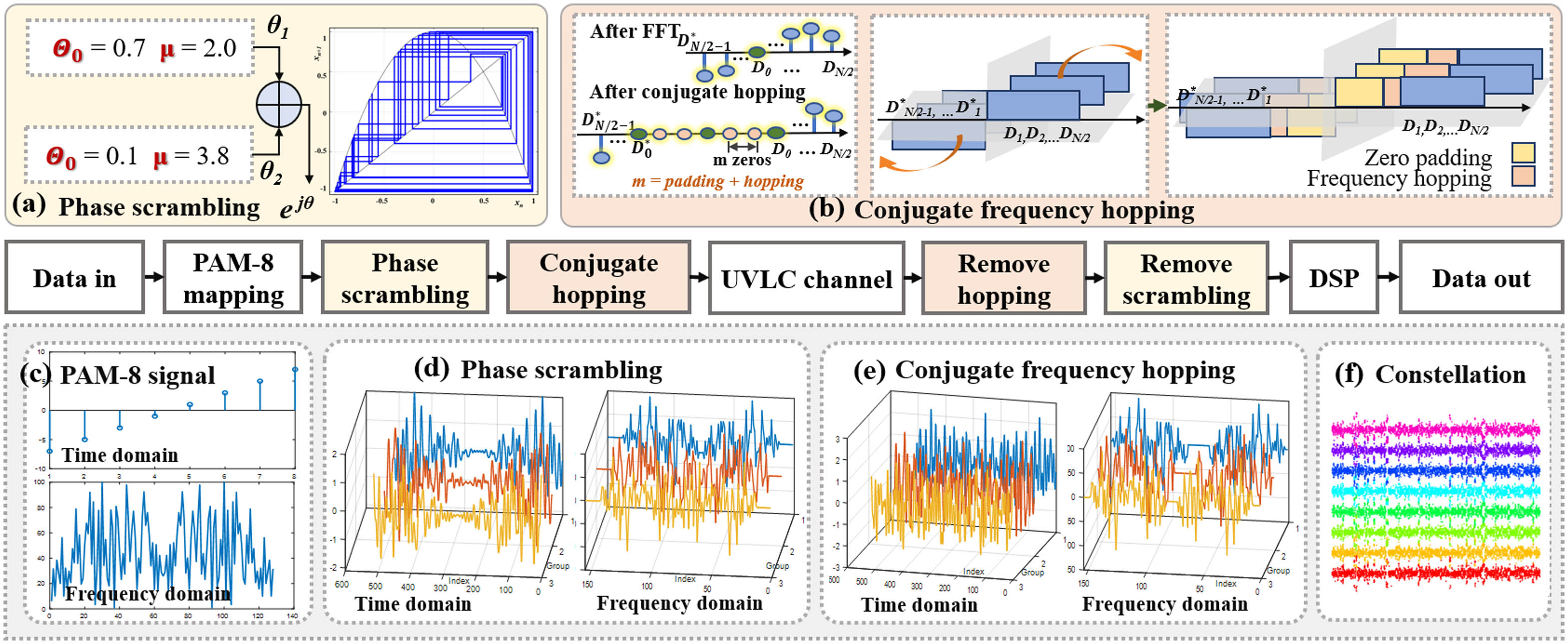
The principle of the proposed scheme is described as Fig. 1. The original bit data are first mapped into the PAM-8 signal. Then, two major methods, logistic phase scrambling and conjugate frequency hopping, are implemented to the signal after fast Fourier transform (FFT) to increase its security characteristic. After inverse fast Fourier transform (IFFT) and UVLC transmission, the received signal is de-hopping and de-scrambling for digital signal processing (DSP) and PAM demodulation.
![]()
Figure 1.The principle of the proposed scheme. The original bit sequence is mapped into the PAM-8 signal. After FFT, two major methods, logistic phase scrambling and conjugate frequency hopping, are implemented. After IFFT and UVLC transmission, the received signal is dehopped and descrambled for DSP and demodulation.
PAM-8 modulation uses , , , , 1, 3, 5, and 7 to represent 8 symbols. Each symbol carries 3 bits of information. According to Refs. [12–15], PAM mapping is a simple but effective coding method, and in the UVLC system with a given signal-to-noise ratio, the PAM-8 signal has a higher spectrum efficiency when compared with a lower level of PAM modulation like PAM-4 modulation. We first generate a 76,800-bit sequence and divide it into 200 groups after PAM-8 modulation. That is, we obtain a signal matrix . After FFT, we obtain the conjugate symmetrical frequency-domain signal of the real PAM-8 signal, where is the length of each group, and .
Since the frequency spectrum of the signal has conjugate symmetry and the phase scrambling and conjugate frequency hopping are implemented in the frequency domain, we can simply analyze the positive half-axis of the spectrum ,
The positive and negative half-axes satisfy the following relationship:
Then, we implement phase scrambling by using a linear combination of two different logistic-based chaos mappings, which can be illustrated as
Each logistic mapping is uniquely determined by the initial value and the bifurcation factor . The parameter determines whether the system is stable or under chaos. The logistic maps generated by Eqs. (8) and (9) with changing are shown in Fig. 2. When the system is under chaos, a slight difference in the initial value can cause large differences over time, which is known as the sensitivity to the initial value, one of the most important characteristics of chaos systems[17]. In this paper, we use Eq. (8) and set , to generate the first chaos mapping . Similarly, we use Eq. (9) and set , to generate the second mapping . In order to increase the complexity of the key while taking into account the computational complexity, the post-processing scheme we use is a weighted summation of two different chaotic sequences. That is, the phase scrambling code is calculated by linearly combining and and multiplying it by a weight . For application to real systems, we need to increase the complexity of the post-processing algorithm, similar to the sorting operation in Ref. [10] or the XOR operation in Ref. [11].
![]()
Figure 2.Logistic maps generated by (a) Eq. (
After phase scrambling, we apply conjugate frequency hopping to the signal, whose detailed scheme is shown in Fig. 1(b). We set the signal whose length is 4 times the original spectral signal and whose dimension is . As the whole system has bandpass characteristics, the direct current (DC) component and the low frequency parts of the signal will all be attenuated. To deal with this problem, we first apply points of zeros at the zero and low frequencies, called zero padding, with . Then, we randomly generate 200 conjugate hopping factors ranging from 1 to 5. For each group, we add an additional number of zeros to the low frequencies according to the corresponding hopping factor. Accordingly, we add the same number of zeros to the negative half-axis of the spectrum. To maintain the conjugate symmetry of the frequency spectrum, we add an extra zero directly at the DC component. The time-domain and frequency-domain signals after conjugate hopping are shown in Fig. 1(e). The principle of conjugate frequency hopping can be illustrated as
Finally, we apply IFFT and obtain the real time-domain signal of
3. Experimental Setup
The experimental setup of the proposed scheme is shown in Fig. 3. At the transmitter side, the digital signal to be transmitted is obtained after the PAM8 mapping of the bit sequence. After Fourier transform, phase scrambling, conjugate frequency hopping, and inverse Fourier transform, the digital signal is fed into an arbitrary waveform generator (AWG) for conversion into an analog signal. An electric amplifier (EA) is used to amplify the signal, and a bias-Tee is used to couple a direct current (DC) signal. Next, the blue LED with a wavelength of 450 nm is driven, and the beam is transmitted through the lens for collimation into a 1.2 m water tank.
![]()
Figure 3.Experimental setup of the proposed scheme for UVLC links. Arbitrary waveform generator, AWG; electric amplifier, EA; positive-intrinsic-negative photoelectric diode; PIN-PD; oscilloscope, OSC.
At the receiver side the light is first focused through the lens to the receiver, where a Si PIN-PD is used for photoelectric conversion. After the electronic amplifier, the received signal is sampled by an OSC and used for off-line processing.
In the offline processing module at the receiver side, the received signal is first synchronized, and then a least-mean-square (LMS) filter and a Volterra filter are used for signal equalization, followed by conjugate frequency hopping and phase scrambling code removal. Next, the decrypted signal is filtered by a second LMS for noise removal, and the obtained signal is then demodulated for BER testing.
4. Results and Discussion
We experimentally test and evaluate the performance of the above system using a BER and a secure key space. We randomly generate 76,800 bits of data and map it into a PAM-8 signal. After quadruple up-sampling and encryption, we transmit the signal through a 1.2 m water tank and obtain the received signal for decryption and decoding.
We first investigate the optimal operating point of the system by varying the bias current and the peak-to-peak voltage of the AWG separately. Figure 4 is a two-dimensional thermodynamic diagram of the BER performance, which changes with the and the . When the is fixed, with the increase of bias current , the BER decreases to a minimum value and then increases. The same situation happens when we increase the and the is fixed. When the and the are set too high, the BER will increase due to a nonlinear effect. When the power of the signal is too high, it may cause the power amplifier to enter the nonlinear region. In addition, the system uses intensity modulation and direct detection, both of which can also introduce nonlinearity during the conversion of the optical and electrical signals. An increase in DC bias also raises the peak in the signal, making it more likely to enter the nonlinear region. The nonlinearity increases the intensity noise of the PAM-8 signal and causes deterioration of the system performance. On the contrary, if the and the are low, the SNR of the received signal will diminish, as a result of which the BER will rise. Therefore, according to the experimental results, there is a global optimal working point for our system, which is obtained when the and the , and the BER is under the 7% HD-FEC limit of .
![]()
Figure 4.BER performance versus the bias current Ib and the peak-to-peak voltage Vpp of the AWG.
Then, under the optimal working point, we explore the influence of the transmission speed on our system. As shown in Fig. 5, when the conjugate frequency hopping and phase scrambling codes are not removed at the receiver side (red line), the BER is about 0.5, indicating that even if the receiver side eavesdrops the signal, the correct transmission signal cannot be obtained without the correct key for decryption, which confirms the security of the experimental system. When the decryption is performed correctly at the receiver side (blue line), BER also rises gradually as the transmission speed rises. The reason is that when the transmission is accelerated, the intersymbol interference (ISI) at the receiver side is aggravated due to the limited sampling rate and bandwidth of the system. When the BER is below 7% the HD-FEC threshold, the highest transmission speed that can be obtained is 2.1 Gbit/s, and the BER at this speed is . The constellation diagram of the PAM-8 signal obtained by correct decryption at the receiver side is shown in Fig. 5(c).
![]()
Figure 5.BER versus the transmission speed. Insets are the constellation diagrams.
Accordingly, the constellation diagram that is not correctly decrypted is shown in Fig. 5(a), and the eavesdropper cannot obtain the valid information of the transmitted signal. When the transmission speed is higher than 2.1 Gbit/s, the constellation diagram of the correctly decrypted PAM-8 signal is shown in Fig. 5(b), and the boundaries between the two symbols are not as obvious as in Fig. 5(c), which means the possibility of misclassification will rise.
The effect of the phase scrambling weight on the system performance at the optimal operating point and the highest transmission speed is shown in Fig. 6. When the conjugate frequency hopping and phase scrambling are not properly removed (blue line), and when only the phase scrambling is removed (orange line), we cannot decode the signal correctly to obtain useful information, and the BER is about 0.5. When only the conjugate frequency hopping is removed at the receiver side (green line), the transmission BER also rises gradually as the scrambling weight rises, implying that scrambling codes with high weights require higher accuracy of encryption at the receiver. The scrambling code with low weight has less influence on the signal and can be removed as system noise by the receiver, and the encryption effect is poor. When the weight is 50%, the constellation diagram at the receiver side is shown in Fig. 6(b), where there are almost no boundaries between the adjacent symbols, and it is extremely difficult to classify them correctly. When the conjugate frequency hopping and phase scrambling codes are correctly removed (red line), the highest weight we can obtain is 50%, and the BER is .
![]()
Figure 6.BER versus the phase scrambling coding weight w. Insets are the constellation diagrams.
Finally, we analyze the encryption performance of the system. We begin with the analysis of the chaotic phase scrambling code. Since the parameters to be determined are the initial values and the bifurcation factors of the two chaotic maps and , as well as the coefficients and of the linear combination of the two maps, there are six unknown parameters. As the accuracy of the AWG we use is 8 bits, the phase scrambling code provides a key space of . Then, the conjugate frequency hopping provides a key space of since the number of hopping codes is 200 (the number of groups of PAM-8 signals), and their values are integers varying from 1 to 5. Therefore, the key space of the system is up to . We can see that the system has high security, which mainly comes from the conjugate frequency hopping. Figure 7 shows the decryption results obtained at the receiver side with fixed hopping codes varying from 1 to 5 (the box plot). No matter what the hopping code is, the BER cannot be reduced to the threshold and is close to that without processing the phase scrambling and conjugate hopping (red line). Although a large part of the key space is provided by conjugate frequency hopping, the role of chaotic phase scrambling cannot be denied. If only conjugate frequency hopping is used, then the eavesdropper may observe the encryption of conjugate frequency hopping by analyzing the spectrum of the signal. Therefore, the conjugate frequency hopping and phase scrambling codes proposed in this paper are both complementary and indispensable.
![]()
Figure 7.BER versus the different decryption technology.
5. Conclusion
In this paper, we propose a new two-dimensional encryption technology for an underwater visible light communication system based on logistic chaotic phase scrambling and conjugate frequency hopping. We experimentally validate it with PAM-8 modulation and a 1.2 m underwater link and obtain the highest transmission rate of 2.1 Gbit/s. Unlike traditional frequency hopping communication, which changes the carrier frequency of the signal according to a certain rule, the conjugate frequency hopping technique here is realized by symmetrically adding a certain number of zero frequency points to the DC and low frequency components of the spectrum so that the conjugate symmetry of the signal spectrum can be maintained and the signal after conversion to the time domain is still a real signal. In addition, due to advantages such as initial value sensitivity and randomness encryption using logistic chaotic mapping can improve the security of the transmission. After two-dimensional encryption, a key space of can be obtained. The feasibility of the proposed scheme is verified, with high security robustness and low complexity at the same time, which has the potential to be used in practical applications.
References
[1] H. Kaushal, G. Kaddoum. Underwater optical wireless communication. IEEE Access, 4, 1518(2016).
[9] Y. Zhou, J. Shi, J. Zhang, N. Chi. Spectral scrambling for high-security PAM-8 underwater visible light communication system. Asia Communications and Photonics Conference, Su1G.4(2018).
[16] Z. Hua, Y. Zhou. Dynamic parameter-control chaotic system. IEEE Trans. Cybern., 46, 3330(2016).

Set citation alerts for the article
Please enter your email address
© Copyright 2018-2021 | Chinese Laser Press. All Rights Reserved 沪ICP备15018463号-20