
Shanshan Cheng, Kunpeng Jia, Chi Zhang, Xiaohui Tian, Zhenda Xie, Shi-Ning Zhu. Waveguide-resonator coupling structure design in the lithium niobate on insulator for χ(2) nonlinear applications[J]. Chinese Optics Letters, 2023, 21(5): 051301
- Chinese Optics Letters
- Vol. 21, Issue 5, 051301 (2023)
Abstract
1. Introduction
Lithium niobate on insulator (LNOI) has attracted widespread attention in the optics community for its wide transparent window, high electro-optic coefficient, and nonlinearity. Such unique performance enables massive photonic devices[1–5] based on LNOI, including waveguides, microrings, and microdisk resonators, pushing forward the development of next-generation integrated nanophotonics. Recently, high-efficiency frequency conversion[6–8], broadband frequency comb generation[9–11], and quantum applications[12–15] spanning an octave have been successfully achieved in microrings based on LNOI. Such broadband applications rely on not only the high nonlinearity of lithium niobate, which is enhanced by the tight confinement and the large number of circulation times of optical waves but also the proper design of waveguide configuration for efficient energy coupling over a wide waveband. However, to date, there have not been many studies on the tuning of the bus waveguide over a wide spectral range on LNOI to control the energy coupled into the microring.
The light coupling is generally based on the phase matching and overlap between the mode field and the evanescent field of microrings and bus waveguides, respectively. The straight bus waveguide[16,17] is most commonly used for light coupling due to its simple structure for both design and fabrication, and the waveguide-resonator coupling at a single wavelength can be manipulated by changing the gap and the structure of the bus waveguide. However, since the phase matching and mode field in the straight waveguide differ with the wavelength, the coupling energy at several wavebands varies greatly; thus, achieving the expected waveguide-resonator coupling at several wavebands is difficult. To solve the problem, a pulley waveguide that wraps around the resonator introduces coupling length—a new variable dimension that adjusts the energy transmission coefficients flexibly, and, in the meantime, the expected waveguide-resonator coupling can be achieved at a wide waveband. Such a structure has been successfully applied to silicon on insulator (SOI)[16,18], silicon nitride[19–21], and some other platforms[22,23] to ease the micromachining pressure, achieve single-mode operation, etc. Here, we focus on the multiwavelength coupling of the pulley bus-resonator in the LNOI platform.
In this Letter, we have studied the pulley bus waveguide-resonator coupling in the LNOI platform through numerical calculation and simulation and realized multiband simultaneous critical coupling. As the energy coupled into the microring is affected by the transverse mode properties, we analyze the influence of the bus waveguide structure and the radius of the microring on the periodic coupling length and phase mismatching. Furthermore, through the coupled mode theory (CMT) and Lumerical simulation, we unveiled the relationship between the energy transfer coefficient and the waveguide length at dual wavelengths. In addition, we also discuss how to avoid and use a series of problems caused by curved waveguides: mode field mismatch loss, triggering higher-order modes, etc. Finally, we realize the control of coupling energy coefficient in the microring resonator at dual wavebands simultaneously, which is of great significance in broadband nonlinear optics and quantum optics applications, such as optical frequency combs.
Sign up for Chinese Optics Letters TOC. Get the latest issue of Chinese Optics Letters delivered right to you!Sign up now
2. Experiments
For these waveguides separated by a finite distance, these modes, which exist, respectively, in the bus waveguide and the microring, exchange energy if the wave functions of these modes overlap. We use the CMT to analyze the mode coupling between the bus waveguide and the microring resonator. The coupling coefficient and mode overlap between the bus waveguide and the microring[19,20] are
In fact, for the straight waveguide-microring coupling structure, the energy coupled into the microring is affected by the mode field overlap and the mismatched phase, which can be adjusted by changing the bus waveguide structure and the spacing between the waveguide and microring. For the straight waveguide-microring coupling structure, the overlap and phase mismatch between these mode fields are different at different positions of the coupling structure. It is difficult to quantitatively describe the influence of the waveguide structure and the waveguide spacing on the coupling efficiency, which is not a linear process. And this effect varies significantly with wavelength. In previous experiments, the desired coupling in multiple bands can only be achieved by chance.
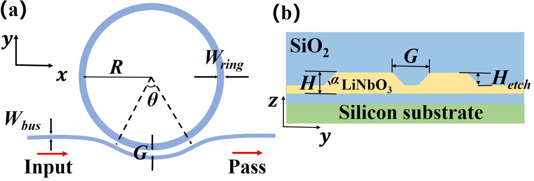
The designed pulley bus coupling structure in this simulation is shown in Fig. 1. In the coupling region, the pulley bus waveguide, whose mode field overlaps with the mode field in the microring, is applied to couple energy into the microring. The coupling structure is fabricated on a z-cut LNOI wafer with silicon oxide cladding. Ridge-shaped waveguides can mitigate scattering losses from sidewall roughness while reducing mode field confinement, and it has been applied in our microring and bus waveguide. In the bus waveguide, there are two transitions from the incident straight waveguide to the curved waveguide, and from the curved waveguide to the output straight waveguide. In the coupling area, the distance between the bus waveguide and the microring remains unchanged. Nonlinear optical conversion across octaves, such as frequency comb generation based on microrings is of great significance. Group velocity mismatch separates the energy of the two bands in the time domain, which reduces the nonlinear energy conversion efficiency. Type I phase matching involving two waves with different polarizations can effectively reduce the group velocity mismatch.
![]()
Figure 1.(a) Coupling structure from a pulley bus waveguide to a ring resonator; (b) cross section of the coupling system composed of the pulley bus waveguide and the microring resonator; θ corresponds to the angle of the interaction part between the two curved waveguides. R represents the radius of the microring. Wring and Wbus represent the width of the ring and the bus waveguide, respectively. H represents the thickness of the structure. Hetch represents the etching depth. G represents the distance between the microring and the waveguide. α represents the inclination of the waveguide.
For the pulley bus waveguide-microring resonator, the accumulated phase becomes
According to Eq. (4), the coupling coefficient varies with the length of the pulley waveguide periodically, and the period and amplitude of the coupling coefficient are affected by the difference between the propagation constants of these two modes and the overlap of these two modes. By controlling the coupling structure, such as the gap between the waveguide and microring, and the width of the bus waveguide, the period and amplitude of the coupling coefficient change. Moreover, there exists a remarkable difference in the mode overlap and phase mismatching at different wavelengths. Light is transmitted from the waveguide to the ring at different speeds in different wavebands, and the maximum transmission energy also varies with wavelength. Compared with the straight waveguide-microring coupling structure, a new adjustable dimension—the length of the pulley waveguide—is introduced, and hence we can achieve the desired coupling in multiple bands simultaneously.
When the light propagates in the waveguide, it will be affected by the evanescent field when it approaches the ring, and then these mode fields affect each other. The bus waveguide and the microring waveguide both construct a system similar to the directional coupler. For the coupling system, we can get the symmetric and antisymmetric modes through mode solution, and the energy coupled into the microring can be obtained from the coherent superposition of these two modes. The maximum coupling energy can be estimated by studying the mode field distribution in the coupling structure. The more uniform the mode field is distributed in these two waveguides, the more energy can be coupled into the microring. The phase mismatching between these two modes determines the periodic length of the waveguide coupling. Figure 2 shows the relationship between the periodic coupling length, the phase mismatching, and the different coupling structures at two wavelengths. The inset in Fig. 2 represents the mode distribution at different structures and wavelengths. As the radius of the microring increases, the periodic coupling length first increases and then decreases. As the width of the bus waveguide increases, the maximum point of the periodic coupling length moves toward the larger ring radius. The reason is that when the width of the bus waveguide increases as it approaches the microring waveguide, the coupling structure tends to be more symmetrical with a longer radius. Therefore, in a nearly symmetrical coupling system, the mode field distributions of the two transverse modes are more uniform, the periodic coupling length increases, and the energy exchange between the two curved waveguides is more sufficient.
![]()
Figure 2.(a) The periodic coupling length and mismatched phase vary with the radius of the ring and the width of the waveguide of vertical polarization at 775 nm. (b) The periodic coupling length and mismatched phase vary with the radius of the ring and the width of the waveguide of horizontal polarization at 1550 nm. Inset in (a) (upper), mode field distribution when Wbus is 1.2 µm and R is 700 µm at 775 nm; inset in (a) (lower), mode field distribution when Wbus is 1.2 µm and R is 400 µm at 775 nm; inset in (b) (upper), mode field distribution when Wbus is 1.2 µm and R is 200 µm at 1550 nm; inset in (b) (lower), mode field distribution when Wbus is 1.2 µm and R is 800 µm at 1550 nm. Wring is 1.7 µm, G is 0.4 µm, α is 70°, H is 0.7 µm, and Hetch is 0.34 µm.
According to Eq. (4), the transmission of energy in the curved bus waveguide section can be determined. Considering only the curved waveguide, we calculated that the energy in the microring varies with the length of the pulley waveguide at dual wavelengths with CMT [Fig. 3(a)]. The period of the coupling angle is 12.3° with TM mode at 775 nm, while the period of the coupling angle is 32.4° with TE mode at 1550 nm. Figure 3(a) also shows that the coupled energy at 1550 nm is an order of magnitude more than the coupled energy at 775 nm. The fundamental cause lies in the diffraction effect at longer wavelengths. As the wavelength increases, it is more difficult for the waveguide to confine the light, and thus the evanescent field is stronger.
![]()
Figure 3.(a) Energy transmission coefficient coupling from the pulley bus waveguide to the ring resonator with different coupling angles considering only the curved waveguide section with CMT; (b) energy transmission coefficient coupling from the input port to the ring resonator with different coupling angles θ at dual wavelengths through 3D FDTD simulation; (c) demonstration diagram of the mode field when light propagates in a curved bus waveguide.
We use simulation software to further describe the light transmission process during the whole structure from the input port to the pass port. The energy transmitted to the microring about different coupling angles is shown in Fig. 3(b). At 1550 nm, the periodic coupling length is consistent with Eq. (4), while at 775 nm, a series of randomly distributed points are observed that do not follow the above-calculated coupling period [Fig. 3(a)] by the coupled mode equation. By observing the mode distribution of the output energy at the pass port of the pulley bus structure at 775 nm, the proportion of the TM fundamental mode is only 37.3578% when the corresponding to the coupling area is 70°. Energy is transferred from the fundamental mode to the higher-order mode. The fundamental reason lies in the mode field mismatch at the interface inside the whole pulley bus structure [Fig. 3(c)]. We can calculate that the mode overlap between these two bending waveguides is about 80.1543%. The mode mismatch loss is the most prominent cause of the total loss in the pulley bus waveguide at 775 nm.
We adopted two methods to reduce the mode field mismatch loss: reducing the bus waveguide width and introducing an offset at the interface. Reducing the width of the straight waveguide can help increase the constraints of the waveguide on the mode field, thereby increasing the mode overlap at the interface and reducing mode mismatch loss. After changing the structure, is 0.6 µm, is 0.4 µm, and almost all of the energy at the pass port of the coupling structure is concentrated in the TM fundamental mode; the energy coupled to the ring corresponding to different coupling angles through 3D FDTD is shown in Fig. 4(a). The period of the coupling angle corresponds to the result of the curved waveguide section with CMT [Fig. 4(b)]. In addition, previous research[24,25] mentioned a way to solve the problem of mode mismatch: setting an offset at the interface of the curved waveguide [Fig. 5(a)]. Therefore, we need to optimize the pulley bus waveguide structure to obtain more sufficient mode overlap. The energy coupled to the microring corresponding to different coupling angles is shown in Fig. 5(b). Overall, after adding the offset, the period of the coupling angle is consistent with the result of the curved waveguide section [Fig. 3(a)]. Although the offset is optimized for the fundamental mode at 775 nm, the energy of the TE fundamental mode does not decrease because of the reduction of the mode field mismatch at 1550 nm. However, there is still a deviation between Figs. 3(a) and 5(b) because in the calculation with the curved waveguide section, the loss of the mode transmission in the waveguide and the inevitable coupling between other parts and the microring are not considered.
![]()
Figure 4.(a) Transmission of coupling energy from the input port to the ring resonator with different coupling angles θ at dual wavelengths; (b) considering only the curved waveguide section, the transmission of coupling energy from the pulley bus waveguide to the ring resonator with different coupling angles θ calculated by the CMT.
![]()
Figure 5.(a) Coupling structure from the pulley bus waveguide to the ring resonator after adding an offset in the interface of the pulley bus waveguide; (b) relationship between the energy coupled into the ring and angle-θ at dual wavelengths in the offset waveguide with 3D FDTD; (c) relationship between the energy coupled into the ring and angle-θ at dual wavelengths in the offset waveguide.
In the above design, we successfully reduced the loss caused by the mode field mismatch at the interface of the pulley bus waveguide by reducing the width of the bus waveguide or setting an offset inside the pulley bus structure. However, the energy coupled into the microring is reduced, and these results are difficult to meet the needs of practical applications because of the low energy transmission coefficient at a near-visible wavelength. Generally speaking, compared with the fundamental mode, the spot area of the high-order mode is larger, the evanescent field of the high-order mode is stronger, and the overlap between the mode fields in the pulley bus waveguide and the microring is more sufficient, which is more conducive to the mutual energy transfer. On the contrary, although mode-field mismatching at the interface of the curved waveguide induces conversion from fundamental modes to higher-order modes and increases the losses in the energy transmission process, it can help to transmit more energy into the microring and make it possible to achieve our desired coupling efficiency at near-visible and infrared wavelengths.
Finally, we designed a new structure to achieve a symmetrical mode field distribution of the system composed of bus waveguides and microring. The curve of the energy transmission coefficient is shown in Fig. 5(c). We can adjust the structure around this structural parameter and realize the desired coupling at dual wavelengths. When the coupling angle is equal to 12°, the energy transmission coefficient is approximately equal to the loss coefficient of the ring, and critical coupling is achieved at two wavelengths.
3. Conclusion
We discussed the influence of the coupling structure, such as waveguide width and ring radius parameters, on coupling length and coupling strength, studied the energy transmission coefficients of multiple structures in detail, and analyzed a series of complex phenomena in the pulley bus waveguide-microresonator structure. This article contributes to the design of a bending waveguide-microring resonator structure in the future. The significance of this research is that it not only solves the coupling problem of microrings based on LNOI in different wavebands, but more importantly, promotes the practical application of second-order nonlinearity of microrings on LNOI.
References
[21] G. Liang, H. Huang, S. Shrestha, A. Mohanty, X. Ji, M. C. Shin, M. Lipson, N. Yu. Micron-scale. Efficient, robust phase modulators in the visible. Conference on Lasers and Electro-Optics (CLEO)(2019).
[23] D. Cai, C. Chen, C. Lee. Pulley-type ring resonator and optimization. 12th International Joint Conference on e-Business and Telecommunications (ICETE), 25(2015).

Set citation alerts for the article
Please enter your email address
© Copyright 2018-2021 | Chinese Laser Press. All Rights Reserved 沪ICP备15018463号-20