
Yafeng Huang, Di Hu, Meifeng Ye, Yating Wang, Yanli Li, Ming Li, Yinnan Chen, Qiuzhi Qu, Lingke Wang, Liang Liu, Tang Li. All-fiber-based ultrastable laser with long-term frequency stability of 1.1 × 10⁻¹⁴[J]. Chinese Optics Letters, 2023, 21(3): 031404
- Chinese Optics Letters
- Vol. 21, Issue 3, 031404 (2023)
Abstract
1. Introduction
Ultrastable lasers with high frequency stability and phase coherence are required as fundamental tools in a wide variety of applications, such as optical atomic clocks[1–3], gravitational wave detection[4], low-noise microwave synthesis[5], and fundamental physics tests[6]. To fully meet the demands of those applications, the development of ultrastable lasers with higher frequency stability and coherence has never been suspended. Currently, the most popular way to achieve ultrastable lasers is to stabilize the laser frequency onto a high-finesse Fabry–Perot (F-P) cavity by using the Pound–Drever–Hall (PDH) method. This kind of approach can reach a fractional frequency instability as low as [7]. However, it requires fine alignment of free-space optical components and precise spatial mode matching, which dramatically increases the complexity and bulk of the system and is easily disturbed by the external environment[7–9]. Therefore, it is difficult to meet the requirements in the transportable applications of ultrastable laser systems, such as local oscillators in optical atomic clocks for geodesy[10], the space missions for gravitational wave detection[11,12], and optical frequency dissemination[13].
An alternative approach is to use an optical fiber delay line (FDL) as a frequency discriminator to stabilize laser frequency. Compared to the F-P cavity method, this approach has the advantages of high compactness, high reliability, small volume, and light weight. Moreover, the system can provide not only high frequency stability and phase coherence, but also precise and rapid tunability over a wide frequency range[14–17]. Benefiting from these advantages, except for the above-mentioned applications, an FDL-stabilized laser has potential applications in the fields of low-noise interferometric sensors[18], optical processing of RF signals[19], and coherent light detection and ranging[20]. In the latest work[17], to improve the influence of the thermomechanical noise, an FDL-stabilized laser using 5-km-long optical fibers was demonstrated. The optical fiber length is 10 times longer than in the previous work[16], and in this way, a short-term frequency stability of (2 s to 4 s) is achieved. However, all the previous works did not concern themselves with long-term frequency stability, but with short-term frequency stability. The laser frequency stability at a longer time scale beyond 10 s showed fast degradation, which is mainly due to the temperature fluctuation of the FDL. This will restrict the application of such kinds of stabilized lasers. To achieve a high long-term frequency stability, it is necessary to evaluate and reduce the temperature fluctuation of the FDL.
In this paper, we demonstrate an ultrastable laser with a long-term frequency stability of that is locked to an all-fiber-based interferometer. In contrast to previous works[14–17], we evaluate and reduce the laser frequency noise induced by the temperature fluctuation of the FDL, including cabinet environmental temperature fluctuation, optical power fluctuation dissipated in the optical fiber, and RF power fluctuation driving the acousto-optic modulator (AOM).
Sign up for Chinese Optics Letters TOC. Get the latest issue of Chinese Optics Letters delivered right to you!Sign up now
2. Principle and Experimental Setup
In this approach, an arm-unbalanced heterodyne Michelson interferometer is used as a frequency discriminator to convert the frequency fluctuation () of the laser into the phase fluctuation () of the heterodyne signal, which is then fed back to the laser to correct its frequency fluctuation[14–17]. Therefore, the output frequency of an FDL-stabilized laser can be described as
For the SMF-28 optical fiber we used, the values of and are [21] and [22], respectively. For the ultralow-expansion (ULE) glass used in the F-P cavity method, the thermal expansion coefficient is better than from 5°C to 35°C[23].
Compared to the F-P cavity method, it can be seen clearly that the FDL-stabilized laser is more sensitive to temperature fluctuation, owing to the almost 3 orders of magnitude higher temperature coefficient of the optical fiber. The temperature fluctuation of the interferometer will cause slow laser frequency fluctuation, resulting in long-term frequency instability. Therefore, the temperature stabilization of the interferometer is of importance. In the FDL-stabilized lasers, the temperature fluctuations of the interferometer mainly come from cabinet environmental temperature fluctuation, optical power fluctuation dissipated in the optical fiber, and RF power fluctuation driving the AOM of the interferometer. The RF power fluctuation will result in temperature fluctuation of the AOM, which does not only cause phase variation of the light propagating in the AOM, but also can be transferred to the optical fiber inside the thermal shields by heat conduction and radiation. To migrate these problems, several modifications are adopted in this research. First, a vacuum chamber and a five-layer thermal shield are used to depress the outside temperature fluctuation. Second, a two-stage active temperature stabilization is employed to keep long-term temperature stability. This kind of stabilization can provide lower than 0.5 mK temperature variation over a period of 24 h. Third, both the optical power injected into the interferometer and the RF power driving the AOM are precisely stabilized. The bandwidths of the RF power and optical power stabilization circuits are about 20 kHz and 100 Hz, respectively, which are mainly limited by the variable RF attenuator (MVA-2000+, Mini-circuits) and the microelectromechanical systems (MEMS) variable optical attenuator inside the laser source.
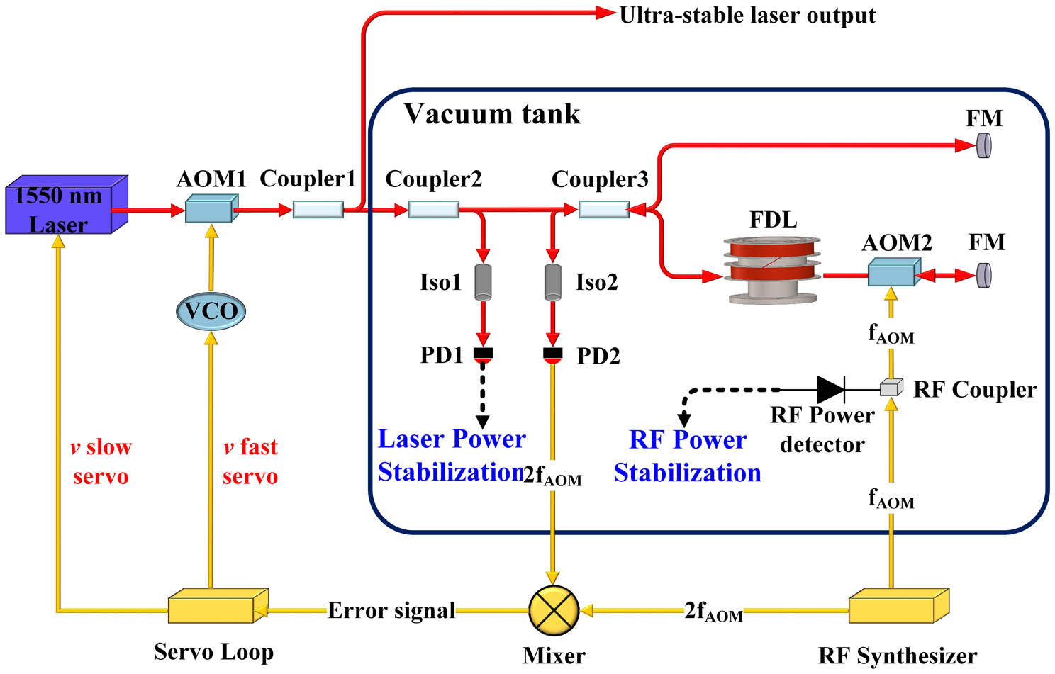
The schematic of the FDL laser frequency stabilization is shown in Fig. 1. Coupler3, FDL, AOM2, and two Faraday mirrors (FMs) construct the heterodyne fiber Michelson interferometer. A 1550 nm single-frequency laser module (Basik-x15, NKT Photonics) is used as the laser source. The laser beam passes through AOM1, and then is split into two parts by Coupler1 with a coupling ratio of 95:5. The large part serves as the ultrastable laser output, while the small part is sent to Coupler2 with a ratio of 50:50. One output of Coupler2 is used to stabilize the optical power, and another is sent to the interferometer for frequency stabilization. In the interferometer, AOM2 is used to produce an RF shift for heterodyne detection. The driving RF signal comes from a frequency synthesizer, and the power is also stabilized. The driving frequency of both AOMs is 80 MHz. The heterodyne signal is detected by the photodetector (PD2) and then demodulated by the frequency-doubled signal of the signal driving the AOM2, which is provided by a home-made tunable synthesizer. A proportional-integral servo circuit then converts this error signal into a laser frequency correction signal that simultaneously acts on a piezo-electric transducer (PZT) stretcher and a voltage-controlled oscillator driving the AOM1.
![]()
Figure 1.Schematic of the FDL laser frequency stabilization. AOM, acousto-optic modulator; Iso, optical isolator; PD, photodetector; FDL, fiber delay line; FM, Faraday mirror; RF, radio frequency; HMI signal, heterodyne Michelson interferometer signal.
3. FEM Simulations
In order to depress the temperature fluctuation, the entire interferometer, including the fiber spool, fiber couplers, and FMs, is enclosed in a vacuum chamber with a five-layer thermal shield, as shown in Fig. 2. The thermal shields can be treated as a series of low-pass filters for reducing temperature fluctuations. Each thermal shield plate has three trapezoidal slots symmetrically distributed on both sides, and a Teflon rod is placed in the slot to isolate the heat from the outer shield. Meanwhile, each layer of the shields is treated by polishing and gold-plating to minimize thermal radiation. The solar absorptivity of the shield surface is about 0.3, and the emissivity is about 0.03. Additionally, a two-stage active thermal controller is used in this system. The first stage temperature stabilization is applied on the vacuum chamber with a temperature fluctuation less than 2.5 mK over a 24 h period. The second stage temperature stabilization is applied on the outer-layer thermal shield using thermoelectric coolers (TECs) mounted between the shield and the chamber, and the temperature fluctuation can be further minimized within 0.5 mK. In addition, the optical power stabilization and RF power stabilization circuits are also mounted inside the vacuum chamber by heat-insulating pads to reduce convective heat exchanges for stabler temperature.
![]()
Figure 2.Schematic of the vacuum chamber.
Using a finite-element-method (FEM) analysis, a simulation is implemented to verify the effect of the thermal shields. We find that the sensitivity of optical fiber inside the thermal shield increases exponentially with the layer of the shield. To achieve a high performance of the FDL-stabilized laser, a five-layer thermal shield is used in this system, as shown in Fig. 3. The calculated time constant of the five-layer thermal shield is about 6 d. For temperature perturbation with a period of 1000 s applied on the outer-layer thermal shield, which is temperature-stabilized by the second stage temperature controller, the sensitivity of the optical fiber inside the five layers of thermal shield is , calculated from Fig. 3(b). In the calculation, the 1000 s varied perturbation simulates the ambient temperature fluctuation, which has a period of about 1000 s and results from the air conditioner in the laboratory. For a perturbation of 0.5 mK, which is the control accuracy of the second stage temperature controller, the optical fiber “feels” a temperature fluctuation of . The induced frequency instability of the FDL-stabilized laser is about , which is better than the thermomechanical noise limit of the optical fiber.
![]()
Figure 3.Temperature distribution nephogram and fluctuations of components inside the vacuum chamber. (a) Temperature nephogram of the five-layer thermal shield, AOM, and fiber spool; (b-1) temperature fluctuation of the first-layer shield; (b-2) simulated temperature fluctuation on the optical fiber; (c-1) temperature fluctuation of the vacuum chamber; (c-2) simulated temperature fluctuation on the optical power and RF power circuits.
Meanwhile, to verify the frequency stabilization ability of optical power and RF power feedback circuits, the frequency noises without and with power feedback are evaluated and compared as follows. As shown in Figs. 4(a) and 4(b), the free-running optical relative power fluctuation is about , while the RF is about , corresponding to a optical power variation for 50 µW injected optical power and 180 µW RF power variation for 200 mW injected RF power. Here, the optical power of 50 µW and the RF power of 200 mW are operating parameters in this system. By introducing a slightly optical power and RF power fluctuation, respectively, the frequency sensitivities to optical power and RF power are measured as and , respectively [Figs. 4(c) and 4(d)]. Multiplying the optical power and RF power variations with the frequency sensitivity, the induced frequency noise is 63 and 56 Hz, respectively, corresponding to fractional frequency variation of and .
![]()
Figure 4.Free-running relative power fluctuation to (a) the optical power injected into the interferometer and (b) the RF power driving the AOM2. FDL-stabilized laser frequency step response to (c) the optical power injected into the interferometer and (d) the RF power driving the AOM2.
For the optical power feedback circuit holding inside the vacuum, the power fluctuation is hard to measure directly. The performance of power stabilization is mainly limited by the temperature sensitivity of the circuits, in which the most temperature-sensitive component is the resistor converting the photocurrent from the photodetector into photovoltage. The thermal coefficient of the resistor is , which is defined as the percent change in power induced by a 1 K temperature change. Similarly, the most temperature-sensitive component of the RF power stabilization circuit is the RF power detector (AD8361, Analog Device Inc.), and its thermal coefficient is . Therefore, a temperature fluctuation of 0.63 mK, as mentioned in Fig. 3(d), will lead to an optical power variation of for 50 µW injected optical power and an RF power variation of for 200 mW injected RF power. Multiplying the frequency sensitivity deduced from Figs. 4(c) and 4(d), the induced frequency noise is and , respectively, corresponding to fractional frequency variation of and . It is clear that power stabilization dramatically depresses the frequency instability induced by the optical power and RF power variations.
4. Results and Discussion
To evaluate the frequency stability of the FDL-stabilized laser, we construct two identical ultrastable laser systems. The FDL is a 5-km SMF-28 fiber spool (). In addition to the thermal treatment mentioned above, a low vibration sensitivity fiber spool is used to reduce the vibration-induced frequency noise over a frequency range of several Hz to hundreds of Hz[24]. The two laser systems are separate and identical; thus, their contributions to the measurements can be considered to be the same. The light beams of the two ultrastabilized lasers are combined by an optical fiber coupler, and the heterodyne beat-note signal is detected by a photodiode afterward. A frequency drift rate of 5 Hz/s occurs in the beat-note signal owing to aging drift of the optical fiber. The drift is compensated for by applying a small frequency offset to the tunable RF synthesizer[15], and the residual drift of the measured beat-note signal is less than 0.1 Hz/s.
To measure the laser linewidth, the beat-note signal is frequency downconverted to an approximately low-frequency signal and is then evaluated by a fast Fourier transform (FFT) spectrum analyzer (SR760, Stanford Research Systems). From a series of eight consecutive measurements, we obtained a typical full width at half-maximum of 0.32 Hz (0.04 Hz, standard deviation) at 0.122 Hz resolution bandwidth (shown in Fig. 5).
![]()
Figure 5.FFT spectrum of the beat-note signal (blue circles) and its Gaussian fit (red line).
To measure the frequency noise and the frequency stability, the beat-note signal is sent to a time interval analyzer (Symmetricom 5125 A) for frequency comparison against a reference signal from an active hydrogen maser (iMaser3000, T4Science). The recorded phase data from the time interval analyzer are then used to calculate the frequency noise and the frequency stability of the two lasers. The measured frequency noise power spectral density (PSD) of the FDL-stabilized laser is shown in Fig. 6. The noise bump in the range between 10 and 100 Hz is mainly due to seismic noise.
![]()
Figure 6.Frequency noise PSD of the FDL-stabilized laser.
The measured frequency stability of single laser system is shown in Fig. 7. It is clear that the frequency fluctuation of this work is almost 1 order of magnitude smaller than in our previous work[17]. The dashed curve at a fractional frequency stability of represents the thermomechanical noise limit of the optical fiber. For one laser, the calculated frequency stability should be divided by . A fractional frequency stability of ultrastable laser system of at 1 s averaging time and at 1000 s averaging time is achieved, which is the best long-term frequency stability of a miniaturized transportable FDL-stabilized laser observed to date. The instability deteriorating between 1 s and 4 s is attributed to high-frequency noise, while the rising ramp at time scales above 10 s may come from the excess temperature fluctuation.
![]()
Figure 7.Fractional frequency instability of the FDL-stabilized laser. The inset displays the FDL-stabilized laser frequency fluctuation to the current work (red line) and our previous work (blue line)[
In Fig. 7, the result is more than 1 order of magnitude higher than the caculated thermal effect. One of the possible reasons may come from the polarization-dependent loss of the optical components used in the optical links for optical power stabilization. The fiber feedthrough and its pigtailed fiber are nonpolarization-maintaining. The polarization state of propagating light will vary with temperature or stress and produce excessive optical loss on optical components, which causes excessive optical power variation. Another possibility may come from the RF modulation and demodulation links. The phase of the RF signal will vary with temperature due to the thermal delay effect of the RF links. This phase variation also causes excess frequency noise of the FDL-stabilized laser.
5. Conclusion
In conclusion, using a 5-km-long optical fiber spool, an all-fiber-based ultrastable laser with a long-term frequency stability of at 1000 s averaging time was demonstrated. To achieve optimized long-term frequency stability, the FDL was placed into a vacuum chamber with a five-layer thermal shield, and a delicate two-stage active temperature stabilization, an optical power stabilization, and an RF power stabilization are applied in the system. Using these delicate thermal stabilized measures, the frequency fluctuation of the FDL-stabilized laser is almost 1 order of magnitude smaller than in our previous work[17]. In future work, several attempts can be taken to further improve the long-term frequency stability of the FDL-stabilized laser: (1) optical fiber with lower thermal coefficient such as photonic crystal fiber can be used to reduce the effect of temperature fluctuation[25,26]; (2) constructing the interferometer with polarization-maintaining fiber and utilizing its strong birefringence effects to measure and compensate for the frequency fluctuation induced by the temperature fluctuation[27].
References
[1] A. D. Ludlow, M. M. Boyd, J. Ye, E. Peik, P. O. Schmidt. Optical atomic clocks. Rev. Mod. Phys., 87, 637(2015).
[2] I. Ushijima, M. Takamoto, M. Das, T. Ohkubo, H. Katori. Cryogenic optical lattice clocks. Nat. Photonics, 9, 185(2015).
[3] N. Huntemann, C. Sanner, B. Lipphardt, C. Tamm, E. Peik. Single-ion atomic clock with 3 × 10-18 systematic uncertainty. Phys. Rev. Lett., 116, 063001(2016).
[4] R. X. Adhikari. Gravitational radiation detection with laser interferometry. Rev. Mod. Phys., 86, 121(2014).
[5] Y. Duan, Y. Huang, Y. Li, Y. Wang, M. Ye, M. Li, Y. Chen, J. Zhou, L. Wang, L. Liu, T. Li. All-fiber-based photonic microwave generation with 10−15 frequency instability. Chin. Opt. Lett., 20, 021406(2022).
[6] S. Herrmann, A. Senger, K. Möhle, M. Nagel, E. V. Kovalchuk, A. Peters. Rotating optical cavity experiment testing Lorentz invariance at the 10-17 level. Phys. Rev. D, 80, 105011(2009).
[7] D. G. Matei, T. Legero, S. Häfner, C. Grebing, R. Weyrich, W. Zhang, L. Sonderhouse, J. M. Robinson, J. Ye, F. Riehle, U. Sterr. 1.5 µm lasers with sub-10 mHz linewidth. Phys. Rev. Lett., 118, 263202(2017).
[8] W. Zhang, J. M. Robinson, L. Sonderhouse, E. Oelker, C. Benko, J. L. Hall, T. Legero, D. G. Matei, F. Riehle, U. Sterr, J. Ye. Ultrastable silicon cavity in a continuously operating closed-cycle cryostat at 4 K. Phys. Rev. Lett., 119, 243601(2017).
[9] L. Jin, Y. Jiang, Y. Yao, H. Yu, Z. Bi, L. Ma. Laser frequency instability of 2 × 10-16 by stabilizing to 30-cm-long Fabry-Pérot cavities at 578 nm. Opt. Express, 26, 18699(2018).
[10] J. Grotti, S. Koller, S. Vogt, S. Häfner, U. Sterr, C. Lisdat, H. Denker, C. Voigt, L. Timmen, A. Rolland, F. N. Baynes, H. S. Margolis, M. Zampaolo, P. Thoumany, M. Pizzocaro, B. Rauf, F. Bregolin, A. Tampellini, P. Barbieri, M. Zucco, G. A. Costanzo, C. Clivati, F. Levi, D. Calonico. Geodesy and metrology with a transportable optical clock. Nat. Phys., 14, 437(2018).
[11] G. Wang, Z. Li, J. Huang, H. Duan, X. Huang, H. Liu, Q. Liu, S. Yang, L. Tu, H. Yeh. Analysis and suppression of thermal effect of an ultra-stable laser interferometer for space-based gravitational waves detection. Chin. Opt. Lett., 20, 011203(2022).
[12] J. Luo, L.-S. Chen, H.-Z. Duan, Y.-G. Gong, S. Hu, J. Ji, Q. Liu, J. Mei, V. Milyukov, M. Sazhin, C.-G. Shao, V. T. Toth, H.-B. Tu, Y. Wang, Y. Wang, H.-C. Yeh, M.-S. Zhan, Y. Zhang, V. Zharov, Z.-B. Zhou. TianQin: a space-borne gravitational wave detector. Class. Quantum Grav., 33, 035010(2016).
[13] O. Lopez, A. Haboucha, F. Kéfélian, H. Jiang, B. Chanteau, V. Roncin, C. Chardonnet, A. Amy-Klein, G. Santarelli. Cascaded multiplexed optical link on a telecommunication network for frequency dissemination. Opt. Express, 18, 16849(2010).
[14] F. Kéfélian, H. Jiang, P. Lemonde, G. Santarelli. Ultralow-frequency-noise stabilization of a laser by locking to an optical fiber-delay line. Opt. Lett., 34, 914(2009).
[15] H. Jiang, F. Kéfélian, P. Lemonde, A. Clairon, G. Santarelli. An agile laser with ultra-low frequency noise and high sweep linearity. Opt. Express, 18, 3284(2010).
[16] J. Dong, Y. Hu, J. Huang, M. Ye, Q. Qu, T. Li, L. Liu. Subhertz linewidth laser by locking to a fiber delay line. Appl. Opt., 54, 1152(2015).
[17] J. Huang, L. Wang, Y. Duan, Y. Huang, M. Ye, L. Liu, T. Li. All-fiber-based laser with 200 mHz linewidth. Chin. Opt. Lett., 17, 071407(2019).
[18] J. Hough, S. Rowan. Laser interferometry for the detection of gravitational waves. J. Opt. A, 7, S257(2005).
[19] V. Lavielle, I. Lorgeré, J.-L. Le Gouët, S. Tonda, D. Dolfi. Wideband versatile radio-frequency spectrum analyzer. Opt. Lett., 28, 384(2003).
[20] M. Harris, G. N. Pearson, J. M. Vaughan, D. Letalick, C. Karlsson. The role of laser coherence length in continuous-wave coherent laser radar. J. Mod. Opt., 45, 1567(1998).
[21] N. Yang, Q. Qiu, J. Su, S. Shi. Research on the temperature characteristics of optical fiber refractive index. Optik, 125, 5813(2014).
[22] J. Leng, A. Asundi. Structural health monitoring of smart composite materials by using EFPI and FBG sensors. Sens. Actuator. A Phys., 103, 330(2003).
[23] K. E. Hrdina, C. A. Duran. ULE ® glass with improved thermal properties for EUVL masks and projection optics substrates. Int. J. Appl. Glass Sci., 5, 82(2014).
[24] J. Huang, L. Wang, Y. Duan, Y. Huang, M. Ye, L. Li, L. Liu, T. Li. Vibration-insensitive fiber spool for laser stabilization. Chin. Opt. Lett., 17, 081403(2019).
[25] W. Zhu, E. R. Numkam Fokoua, A. A. Taranta, Y. Chen, T. Bradley, M. N. Petrovich, F. Poletti, M. Zhao, D. J. Richardson, R. Slavik. The thermal phase sensitivity of both coated and uncoated standard and hollow core fibers down to cryogenic temperatures. J. Light. Technol., 38, 2477(2020).
[26] E. N. Fokoua, M. N. Petrovich, T. Bradley, F. Poletti, D. J. Richardson, R. Slavík. How to make the propagation time through an optical fiber fully insensitive to temperature variations. Optica, 4, 659(2017).
[27] T. Yoshino, T. Hashimoto, M. Nara, K. Kurosawa. Common path heterodyne optical fiber sensors. J. Light. Technol., 10, 503(1992).

Set citation alerts for the article
Please enter your email address
© Copyright 2018-2021 | Chinese Laser Press. All Rights Reserved 沪ICP备15018463号-20