
Ji Wu, Li Liang, Kefeng Tu, Kunying Li, Zi Wang, Guoqiang Lü. Serrated periodic electrode for high energy efficiency and large bandwidth acousto-optic modulators[J]. Chinese Optics Letters, 2023, 21(3): 031403
- Chinese Optics Letters
- Vol. 21, Issue 3, 031403 (2023)
Abstract
1. Introduction
The acousto-optic modulator (AOM) is a device that controls the power of a laser beam by means of an electrically driven signal that is based on the acousto-optic effect[1,2]. The acousto-optic effect is generated in acousto-optic crystals. Elastic strain is generated by sound waves through an acousto-optical crystals, causing the refractive index of the medium to change. When the light wave through the medium is disturbed by the sound waves, the diffraction phenomenon will occur. Benefiting from the mechanism of the acousto-optic effect, the AOM has the advantages of small size, low power consumption, and fast rising time, which have been widely applied to the fields of laser communication[3], laser measurement[4], and fiber-optic sensors[5].
In these application areas, power consumption and bandwidth are important indicators of acousto-optic modulation devices. Ultimately, these are closely related to diffraction efficiency. The acoustic beam is an important factor affecting the diffraction efficiency of AOM, which is generated by the electrodes on the transducer through the inverse piezoelectric effect. Nowadays, most of the electrodes on AOM transducers are rectangular. From the spectral analysis, the rectangular electrode produces more sidelobes; this represents a high degree of divergence of the sound beam. This results in lower AOM energy efficiency using rectangular electrodes. In addition, small bandwidth was generated by rectangular electrodes. Olbrish et al. investigated the effect of different geometries of the electrodes on the suppression of the sidelobes of the acousto field[6]. From the spectral analysis, the change of the shape of the electrode can suppress the sidelobes of the acoustic field and concentrate the acoustic beam, which in turn improves the AOM diffraction efficiency. Wachman et al. proposed a side-dithered pseudo-random electrode that can effectively reduce the sidelobes and improve the homogeneity of the sound field[7]. Wu et al. theoretically analyzed the acoustic near-field distribution characteristics of rectangular, diamond, and hexagonal shapes[8]. Hexagonal electrodes have the most uniform sound field distribution for good performance. These efforts are essential to improve the performance of AOM devices.
In this paper, a serrated periodic electrode is proposed. In the direction of vertical light incidence, the acoustic field produced by the serrated periodic electrode is more collimated, which makes less energy escape from the main sound beam and can reduce AOM power consumption. In the direction of light incidence, the divergence angle of the acoustic wave is large due to serrated edge diffraction of serrated periodic electrodes. This makes the AOM bandwidth larger.
Sign up for Chinese Optics Letters TOC. Get the latest issue of Chinese Optics Letters delivered right to you!Sign up now
Simulation and experimental results show that serrated periodic electrodes have the advantages of high energy efficiency and large bandwidth compared to conventional rectangular electrodes. Under certain experimental conditions, the power consumption of AOM with serrated periodic electrodes can be reduced by 40% and the bandwidth increased by 31% compared to the conventional rectangular electrode. This research helps to reduce the power consumption of AOMs and other acousto-optic devices and to increase their bandwidth.
2. Approach
2.1. Analysis of rectangular and conventional apodization electrode
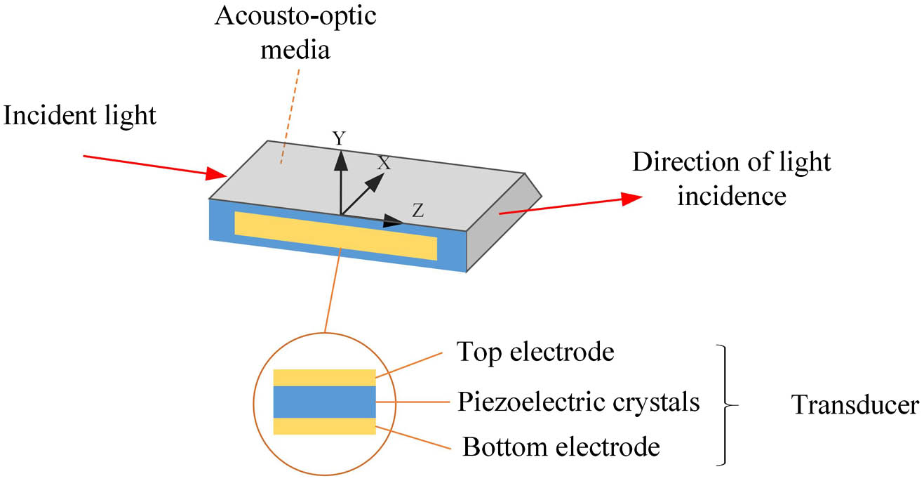
The AOM is an acousto-optic device that converts electrical signals into optical signals based on acousto-optic interactions[9]. It consists of an ultrasonic transducer, an acousto-optic crystal, and an acoustic energy absorption layer, as shown in Fig. 1. The ultrasonic transducer is the component that emits sound waves and consists of three parts: a top electrode, a piezoelectric crystal, and a bottom electrode. Under a high-frequency AC voltage between the top and bottom electrodes, the piezoelectric crystal vibrates at high frequencies to produce ultrasound. The shape and position of the electrodes determine the range of vibration of the piezoelectric crystal and subsequently the distribution of the acoustic field in the acousto-optic crystal.
![]()
Figure 1.The structure of the AOM.
The efficiency of the acousto-optical interaction is mainly limited by the acoustic field in the acousto-optical crystal[8]. The transducer plays a decisive role in the distribution of the acoustic field. The electrodes of the transducer determine the shape of the sound beam. To improve the acoustic field distribution by adjusting the electrode shape, the acoustic field distribution of the conventional rectangular electrode was calculated and analyzed for its deficiencies[10]. A typical AOM is used as the source of the simulation parameters[9]. The length of the electrodes is 29 mm and the height is 1.5 mm. The entire measured acoustic field range is , and the central drive frequency is 80 MHz. The wavelength of the sound wave propagating in the crystal is 71.8 µm. If boundary discretization coarser than is employed, the resulting acoustic field would be distorted because of spatial aliasing[11–13]. For simplicity, we set the sampling spacing to 25 µm. As shown in Fig. 2(a), the sound pressure at each sampling plane along the direction of light incidence ( axis) is superimposed and normalized to obtain the propagation trend of the sound wave along the plane perpendicular to the direction of light incidence. The incident light undergoes Bragg diffraction in the main lobe region of the acoustic wave. However, a portion of the acoustic wave deviates from the main region and does not participate in the acousto-optical interaction, as shown in Fig. 2(b), which reduces the acoustic energy efficiency of the acousto-optical device.
![]()
Figure 2.(a) Rectangular superimposed and normalized sound field distribution; (b) distribution of the acoustical field along the z axis.
Spectrum can be used to analyze the directional distribution of the acoustic beam at rectangular electrodes[14,15]. As shown in Fig. 3(a), according to the angular spectrum theory, the acoustic waves generated by different electrodes can all be expressed as a superposition of plane waves in different directions. And the intensity of the acoustic waves in different directions can be analyzed by analyzing the frequency spectrum of the acoustic waves after Fourier transformation,
![]()
Figure 3.(a) Schematic diagram for analyzing the direction of sound waves using the spectrum; (b) Fourier transform of a rectangular electrode; (c) Fourier transform of a diamond electrode; (d) Fourier transform of a Gaussian electrode.
The rectangular electrode in one dimension can be represented as a rectangular window, whose spectrum is a sinc-squared function. The sinc function has several significant side flaps, which can explain the divergence of the acoustic beam from the rectangular electrode. In the study of acousto-optical devices, apodization electrodes can be used to reduce the acoustic beam in other directions and improve the collimation of the acoustic beam[16–18]. As shown in Figs. 3(c) and 3(d), diamond and Gaussian electrode shapes have a high suppression of sidelobes in the spectrum. However, the AOM based on diamond and Gaussian electrodes does not modulate the incident light uniformly. In an AOM, the width of the incident light is slightly smaller than the width of the main sound beam to ensure that the entire beam is involved in the acousto-optic interaction. Ideally, the length of any part of the beam involved in the acousto-optical interaction should be equal. The area of the acoustic beam is mainly distributed directly above the electrode area. As shown in Fig. 4, the acousto-optical interaction length of marginal incident light is much shorter than that of the center incident light, which results in an uneven intensity of the diffracted beam.
![]()
Figure 4.(a) Acousto-optical interaction length of the diamond electrode; (b) acousto-optical interaction length of the Gaussian electrode.
2.2. Serrated periodic electrode
In conjunction with the analysis of the advantages and disadvantages of rectangular and conventional apodization electrode in Section 2.A, a serrated periodic electrode is proposed. First, the serrated periodic electrode inherits the advantages of the variable trace electrode and improves the collimation of the acoustic wave perpendicular to the direction of light incidence. As shown in Fig. 5(b), the sidelobes are suppressed in the spectrum of the serrated periodic electrodes.
![]()
Figure 5.(a) Simulation size of serrated periodic electrode (in mm); (b) Fourier transform of the serrated periodic electrode.
Second, as shown in Fig. 6, the serrated periodic electrodes extend the acousto-optical interaction length of marginal incident light. In addition, the acoustic waves emitted by this serrated edge fill the acoustic-free area between the serrations along the axis, resulting in a longer acousto-optical interaction area for the marginal incident light.
![]()
Figure 6.Acousto-optical interaction length of the serrated periodic electrode.
Third, the serrated electrode edges increase the divergence angle of the sound waves in the vertical light incidence direction, which enhances the bandwidth of the AOM. As shown in Eq. (2), divergence angle tends to be negatively correlated with the length of the electrode structure,
In addition, the serrated periodic electrode has a greater impedance than a rectangular shape of the same size due to the smaller area. As a result, the serrated electrode has a larger AC voltage at the same input power.
3. Simulation
Simulation results are presented to verify that the acoustic beam emitted by the serrated periodic electrode is collimated in the direction perpendicular to the incidence of light and has a large divergence angle in the direction of light incidence. To clearly demonstrate the effect, we have changed the internal width of the serrated periodic electrodes, as shown in Fig. 7. The calculated acoustic field distribution is superimposed along the axis, and the phase distribution is taken out. The simulation results show that the waveform of the acoustic wave gradually changes from a plane wave to a wavy waveform as decreases. The advantage of a wavy waveform is that it produces a large angle of divergence of the acoustic wave compared to a plane wave, which facilitates the increase in bandwidth.
![]()
Figure 7.(a) Phase distribution at sawtooth period electrode (inner width 0.5 mm); (b) phase distribution at sawtooth period electrode (inner width 0.8 mm); (c) phase distribution at sawtooth period electrode (inner width 1.3 mm); (d) phase distribution at rectangular electrode.
On the other hand, we calculated the amplitude distribution in the direction of vertical light incidence for serrated periodic electrodes with different internal widths. The calculated acoustic field distribution is superimposed along the axis, and its amplitude distribution is taken out. As shown in Fig. 8, as the internal width of the serrated electrode decreases, the sidelobes of the sound field intercept become smaller. This means that the acoustic beam is collimated, and there is no excess escaping energy. This is effective in reducing power consumption when acousto-optical diffraction occurs.
![]()
Figure 8.(a) Amplitude distribution of rectangular electrode; (b) serrated periodic electrode (inner width: 1.3 mm); (c) serrated periodic electrode (inner width: 0.8 mm); (d) serrated periodic electrode (inner width: 0.5 mm).
4. Experiment
4.1. Equipment and materials
We conduct comparative experiment on our AOMs with serrated periodic and rectangular electrodes to verify the effectiveness of the serrated periodic electrode. To obtain AOMs for experiment, 0° X quartz crystal is used as the AO medium, 36° Y is used as the piezoelectric material to excite longitudinal acoustic wave, and 1064 nm antireflective film is plated on the light pass surfaces. The opposite side of the transducer is designed as an inclined plane for multiple reflections to absorb and dissipate heat. The fabricated AOM is shown in Fig. 9, and the effective light incident area is about 3.5 mm away from the transducer. In order to improve the measurement accuracy, the five-dimensional controllable motor scanning platform is used in the test process to avoid the errors caused by human measurement factors (see Fig. 10). The test platform can collect the optical power data in real time and calculate the average value synchronously to reduce the measurement errors. A thermoelectric cooler (TEC) radiator is installed under the AOM fixture to reduce the interference of the temperature gradient field to the supersonic field in AOM.
![]()
Figure 9.Typical AOM configuration with serrated periodic electrode.
![]()
Figure 10.Five-dimensional controllable motor scanning test platform.
As shown in Fig. 11, the length and width of the electrode are 29 mm and 1.5 mm for the AOM. And, three control groups with different inner width are designed for serrated periodic electrodes, including , 0.8 mm, 1.3 mm and . The center frequency of the AOM is 80 MHz, a solid-state 1064 nm laser with a beam diameter of 1.2 mm is used, and the beam divergence angle is about 1 mad.
![]()
Figure 11.Serrated periodic electrodes with different inner widths.
4.2. Experiment and analysis
In order to verify the effectiveness of serrated periodic electrodes, we compare and analyze the samples from three aspects, including sound energy efficiency, acoustic field collimation, and bandwidth.
First, we experimentally compare the sound energy efficiency of serrated periodic electrodes and rectangular electrodes. The sound energy efficiency is measured when the incident light is fixed 1.5 mm away from the transducer. As shown in Fig. 12, under the same experimental conditions, we obtained the diffraction efficiency curves of AOMs with different electrode sizes under varying RF powers. It can be seen from the test efficiency curves that the serrated periodic electrodes can obtain higher efficiency at lower power. The diffraction efficiency peaks of serrated periodic electrodes , 0.8 mm, 1.3 mm appear at 14 W, 16 W, and 20 W, respectively, while the diffraction efficiency peak of the rectangular electrode is 24 W. Under this experimental conditions, the power consumption of AOM with serrated periodic electrodes can be reduced by 40% compared to the conventional rectangular electrode. This is related to the effective sound field width of the AOM. According to the diffraction efficiency relation,
![]()
Figure 12.Diffraction efficiency curves of serrated and rectangular electrodes.
Then, a comparative verification of the acoustic field collimation of the serrated electrode and the rectangular electrode was carried out. A digital holographic interferometer was used to photograph the acoustic field inside the acousto-optical crystal along the direction of the vertical light incidence. As shown in Fig. 13, the serrated periodic electrode has the significant effect of suppressing the acoustic beam outside the main peak.
![]()
Figure 13.(a) Acoustic field distribution inside an acousto-optical crystal with rectangular electrode; (b) acoustic field distribution inside an acousto-optical crystal with serrated periodic electrode (inner width: 0.5 mm).
Also, we measured the diffraction efficiency for different incident light positions along the axis to verify the collimation of the acoustic beam. From the results of the efficiency curve in Fig. 12, the 18 W RF power is selected for testing when both the serrated periodic electrodes and the rectangular electrode have better diffraction efficiency. We scanned along the axis on the scanning test platform. The distance between the tangent of the incident beam parallel to the transducer and the transducer is set as , and the value of is 0–3.5 mm (see Fig. 14). The experimental results of diffracted light efficiency at different sound field propagation depths are shown in Fig. 15. From the comparison of the efficiency curves scanned along the axis, it can be seen that the flatness of the serrated periodic electrodes is better than that of the rectangular electrode while keeping the overall length and width parameters of the electrode unchanged, and as the inner width decreases, the curve becomes smoother. The range of scanning diffraction efficiency of the serrated periodic electrodes at , 0.8 mm, and 1.3 mm is 4.38%, 5.83%, and 8.95%, respectively, while the range of scanning diffraction efficiency of the rectangular electrode is 11.74%. The experimental results are in agreement with the simulation results (see Fig. 8).
![]()
Figure 14.Incident position of the light beam.
![]()
Figure 15.Diffracted light efficiency curves under different incident positions of the beam.
Finally, the comparative verification of the efficiency bandwidth of the serrated periodic electrodes, hexagonal electrodes, and the rectangular electrode is carried out. With a fixed point of action and RF power, the diffraction efficiency of the AOM varies with the RF frequency. The corresponding frequency range from the peak to half is defined as the 3 dB efficiency bandwidth. According to the previous results (see Figs. 12 and 15), a certain propagation depth and RF power when both the serrated periodic electrodes and the rectangular electrode have better diffraction efficiencies are used as the preconditions for the test; that is, the propagation depth is 1.5 mm, and the RF power is 15 W. The efficiency bandwidth tests were performed on sawtooth electrodes and rectangles using the deflector test method; the resulting experimental results are as shown in Fig. 16. The deflector test method shows that the efficiency bandwidths of the serrated periodic electrodes , 0.8 mm, and 1.3 mm are 38 MHz, 34 MHz, and 32 MHz, respectively, while the efficiency bandwidths of hexagonal electrodes and rectangular electrodes are 33 MHz and 29 MHz, respectively. Under these experimental conditions, the bandwidth of the AOM based on serrated periodic electrodes is increased by 31% compared to rectangular electrodes and by 15% compared to hexagonal electrodes. Experimental results proved that, as the inner width of the serrated periodic electrode decreases, the resulting acoustic wave has a greater angle of dispersion in the direction of light propagation, thereby increasing the bandwidth of the device.
![]()
Figure 16.3 dB efficiency bandwidth curves for different electrodes.
5. Conclusion
In this paper, we propose a serrated periodic electrode that is applied to an AOM. The serrated periodic electrode inherits the advantages of the apodization electrode and enhances the collimation of the acoustic beam in the direction of vertical light incidence, and it improves the defect that occurs when the acousto-optical interaction length of the apodization electrode is not uniform. The serrated periodic electrode has a larger bandwidth due to its serrated edge diffraction. The simulation and experimental results demonstrate the high energy efficiency and large bandwidth of the serrated periodic electrode by comparing it with the conventional rectangular electrode. In future work, we will compare the serrated periodic electrodes with other apodization electrodes to refine our study. This research will help to reduce power consumption and increase the bandwidth of AOMs and other acousto-optical devices.
References
[1] C. D. Tran. Acousto-optic devices: optical elements for spectroscopy. Anal. Chem., 64, 971A(1992).
[2] Y. Zhang, H. Fan, T. C. Poon. Optical image processing using acousto-optic modulators as programmable volume holograms: a review. Chin. Opt. Lett., 20, 021101(2022).
[3] V. Nikulin, M. Bouzoubaa, V. A. Skormin, T. E. Busch. Modeling of an acousto-optic laser beam steering system intended for satellite communication. Opt. Eng., 40, 2208(2001).
[4] P. Garland. Fluorescence photobleaching recovery: control of laser intensities with an acousto-optic modulator. Biophys. J., 33, 481(1981).
[5] C. Cuadrado-Laborde, M. Delgado-Pinar, S. Torres-Peiró, A. Díezb, M. V. Andrés. Q-switched all-fibre laser using a fibre-optic resonant acousto-optic modulator. Opt. Commun., 274, 407(2007).
[6] K. D. Olbrish, K. K. Shung. Physical apodization of ultrasonic arrays. Proc. SPIE, 3037, 196(1997).
[7] E. S. Wachman, S. J. Geyer, J. M. Recht, J. Ward, B. Zhang, M. Reed, C. Pannell. Simultaneous imaging of cellular morphology and multiple biomarkers using an acousto-optic tunable filter-based bright field microscope. J. Biomed. Opt., 19, 056006(2014).
[8] J. Wu, Z. Xu, K. Li, G. Lv, X. Li, C. Wang. Analysis of acoustic near field characteristics in acousto-optic modulator. IEEE Photonics Technol. Lett., 33, 201(2021).
[9] A. P. Goutzoulis. Design and Fabrication of Acousto-optic Devices(2021).
[10] B. D. Cook, E. Cavanagh, H. D. Dardy. A numerical procedure for calculating the integrated acoustooptic effect. IEEE Trans. Sonics Ultrason., 27, 202(1980).
[11] O. A. Sapozhnikov, S. A. Tsysar, V. A. Khokhlova, W. Kreider. Acoustic holography as a metrological tool for characterizing medical ultrasound sources and fields. J. Acoust. Soc. Am., 138, 1515(2015).
[12] M. Otani, H. Watabe, T. Tsuchiya, Y. Iwaya. Numerical examination of effects of discretization spacing on accuracy of sound field reproduction. Acoust. Sci. Technol., 36, 362(2015).
[13] D. J. Merthe. A sampling theorem for computational diffraction(2013).
[14] M. Bass, I. C. Chang. Acousto-optic devices and applications. Handbook of Optics, 2, 12.1(1995).
[15] V. B. Voloshinov, G. A. Knyazev. Acoustooptic cells with nonuniform length of light-sound interaction. Tech. Phys., 48, 1475(2003).
[16] J. Xu, R. Stroud. Acousto-optic Devices: Principles, Design, and Applications(1992).
[17] A. Yariv, P. Yeh. Optical Waves in Crystals(1984).
[18] S. N. Antonov. Acousto-optic deflector: a new method to increase the efficiency and bandwidth. Tech. Phys., 61, 1597(2016).

Set citation alerts for the article
Please enter your email address
© Copyright 2018-2021 | Chinese Laser Press. All Rights Reserved 沪ICP备15018463号-20