
Kejun Shang, Ming Lei, Haowei Li, Tianqi Zhang, Xiaozhi Yu, Qiang Xiang, Yonglin Na, Lizhe Zhang. Ultra-small interferometric fiber optic gyroscope with an integrated optical chip[J]. Chinese Optics Letters, 2022, 20(4): 040601
- Chinese Optics Letters
- Vol. 20, Issue 4, 040601 (2022)
Abstract
1. Introduction
Interferometric fiber optic gyroscopes (IFOGs) have existed for more than 40 years. They have attained the ultimate theoretical performance and are widely used in inertial navigation systems (INSs) for a range of applications[
Hemispherical resonant gyroscopes (HRGs)[
Several discrete packaged optical devices are usually used in traditional FOGs to realize the functions of receiving, transmitting, splitting, and modulating optical signals. These independent optical devices are usually over 20 mm in size and cannot satisfy the practical demand for miniaturized, low-cost IFOGs. Moreover, the fabrication process of IFOGs is difficult due to the multiple optical path connection points and coiled fiber processing.
Sign up for Chinese Optics Letters TOC. Get the latest issue of Chinese Optics Letters delivered right to you!Sign up now
Navigation-grade (0.01 deg/h) IFOGs (the most widely used type) have typical dimensions of up to about 90 mm. It is becoming increasingly difficult for the SWaP-C performance of navigation-grade IFOGs to meet the requirements of light, small, and high-precision INSs. In order to significantly reduce the SWaP-C and further improve accuracy while maintaining the IFOGs’ principle advantages, innovative methods are needed.
In the 21st century, tremendous progress has been made in optical integration, electronic integration, and optical fiber technology. Integrated optical chips (IOCs) based on Si, , and have demonstrated potential for application in the field of optical communication. They provide a novel and feasible technical route for the optimization of IFOG SWaP-C. Accordingly, IFOGs based on IOC technology have become a global research hotspot.
IFOGs based on integrated technology (where even the sensitive optical fiber loop is integrated on the chip) have been proposed by Honeywell[
As of 2011, more than 24 discrete optical components had been integrated into a hybrid IOC with a size of by the Gener8 Co. and Centre for Photonics (Ipswich, UK)[
In 2014, an IOC based on a silicon platform was proposed by Bookham Co. for application in miniature IFOGs[
In 2017, Tran presented a chip-scale IOC comprising a light source, three PDs, two phase modulators, and two 3 dB couplers. It was based on integrated photonics technology and had an area of only [
In 2019, KVH Co. integrated a polarizer and two Y branches in an IOC to reduce the cost of open-loop IFOGs. The precision of the integrated IFOG was 0.048 deg/h[
In 2020, a near-navigation-grade IFOG based on IOC (comprising an SLD, PD, and coupler) was proposed, and bias instability as small as 0.018 deg/h was demonstrated[
In this paper, an IOC-based IFOG, application-specific integrated circuit (ASIC), and small-diameter sensing coil are proposed. The integrated IFOG combines the advantages of the small size of IOC technology and the high precision of IFOGs. The overall size of the gyro is only , which is equivalent to the world’s smallest IFOG. However, the accuracy of the integrated IFOG is significantly higher and can satisfy the requirements of near-navigation-grade compact INSs.
2. Schematic Design
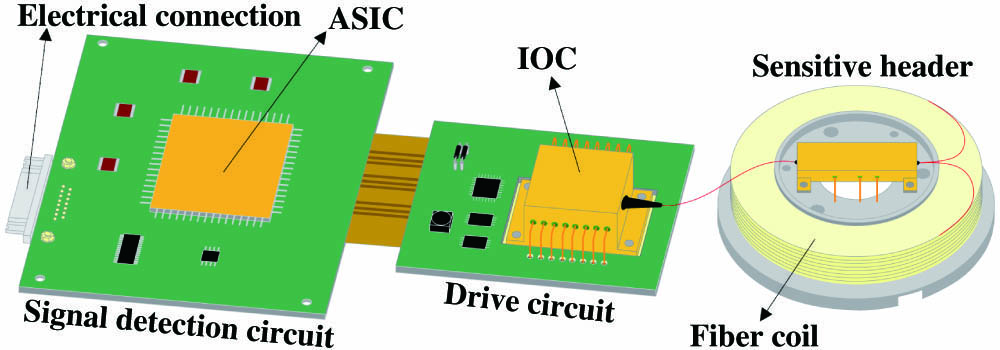
The schematic configuration of the integrated IFOG is shown in Fig. 1. It mainly includes an IOC driven by a drive circuit, a sensitive header (composed of a miniaturized fiber coil, and IOM), and an SDC based on an ASIC. A single-mode fiber is inserted between the IOC and IOM to eliminate the anti-symmetrical mode radiating from the Y-junction and improve the integrated IFOG’s performance. An electrical connection realizes the functions of circuit power supply and data communication.
![]()
Figure 1.Schematic configuration of the integrated IFOG.
Utilization of the IOC and ASIC simplifies the IFOG assembly process, makes it cost-effective, and can accommodate smaller overall sizes than traditional IFOGs. There are only three optical connections: one connection point between the IOC and the input of the IOM, and two connection points between the fiber coil and the output of the IOM. By adopting a modular design scheme, the environmental adaptability (such as temperature, vibration, and overload) of the integrated IFOG can be effectively improved. At the same time, due to the advantages of batch manufacturing of the IOC and ASIC chips, the cost of the IFOG can be reduced and production efficiency improved.
An IOC is the core element of the integrated IFOG, which includes the functions of light emission, detection, and splitting/combining. The gyroscope’s performance is affected by the performance of the IOC. Table 1 gives the key index of the IOC.
| Function | Performance | Required Value |
|---|---|---|
| SLD | Output optical power | |
| Central wavelength | ||
| Spectral width | ||
| Power stability | ||
| Wavelength shift | ||
| PD | Responsibility | |
| 3 dB bandwidth | ||
| Noise voltage | ||
| Dark current | ||
| Coupler | Splitting ratio | <(50 ± 2):(50 ± 2) |
| Insertion loss |
Table 1. Key Index of the IOC
A schematic illustration of the IOC is shown in Fig. 2(a). The Y1 beam splitter chip was manufactured using the optical waveguide integration process. Three separate waveguide chips—the SLD, PD, and beam splitter Y1—were produced in parallel and then integrated into a combined chip by chip-to-chip coupling techniques.
![]()
Figure 2.“Three-in-one” integrated optical chip (a) schematic and (b) photograph.
The SLD is the light-emitting functional unit of the IOC, and its performance directly determines the performance of the IFOG. Using an SLD with high power, a wide spectrum and low-power fluctuation can effectively reduce noise and improve the signal-to-noise ratio (SNR) of an integrated IFOG. The low-temperature drift characteristic of an SLD can effectively improve the scale factor performance of an IFOG over the full temperature range. To expand its bandwidth, we adopted the dual-quantum-well III–V gain medium to expand the bandwidth of the SLD. An optical surface-matching SLD chip was mounted into a planar lightwave circuit (PLC) through chip-to-chip coupling techniques. The main aim is to realize low-loss, high-integration coupling between the SLD chip and Y-branch chip.
As the light-receiving functional unit of the IOC, the PD’s responsivity reflects the sensitivity of the IFOG, while its noise voltage and dark current determine the noise level of the IFOG, and its 3 dB bandwidth determines the response speed of the IFOG. InGaAs was bonded to the substrate by a wafer bonding process with low dark current, high responsivity, and high reliability. The p–n junction in the PIN structure converts light photons into current. The absorbed photons make electron-hole pairs in the depletion region, which is one of the key sub-component technologies required to manufacture etched metalized micro-mirrors that redirect light out of the waveguide and into the surface-mounted PD chip. To improve the absorption coefficient of the material, micro-fabrication processes are optimized. To reduce the dark current, the design of material defects, surface leakage current, and metal-semiconductor contact resistance are optimized.
As the light-splitting/combining functional unit of the IOC, it is necessary to ensure that the beam splitter Y1 has a small insertion loss and precise light-splitting characteristics. A 3 dB passive waveguide coupler is made with doped , which is used to direct 50% of the light propagating in the waveguide into the SLD and PD that are surface mounted on the chip. Through global optimization of the waveguide width, subwavelength structure period, duty cycle, and length of the coupling region, an ultra-small and large-bandwidth beam splitter was obtained.
A “three-in-one” IOC is mounted on a thermal cooler (TEC) to maintain a stable power and wavelength for proper operation. All of these components stand within a metallic package, which is interfaced and wire-bonded to allow electrical contact with electrical pins and a fiber pigtail that isolates the package from external interference. The structure of the IOC package is shown in Fig. 2(b).
A micro high-symmetry fiber coil is the core sensitive element of the integrated IFOG, which has three aspects: (1) its overall dimensions directly limit the final size of the gyroscope, (2) its length/diameter and loss directly limit the ultimate accuracy of the gyroscope, and (3) its symmetry and extinction ratio directly limit the environmental adaptability of the gyroscope (temperature, vibration, magnetic fields). A thin-clad polarization-maintaining fiber with dimensions of 60/100 µm is used to wind the micro-fiber coil to satisfy the miniaturization requirements of the integrated IFOG. The temperature field uniformity of the fiber coil is effectively improved when reducing the size of the fiber coil. For this reason, the temperature sensitivity of the integrated IFOG is reduced. To solve the problems of geometric and stress symmetry in the fabrication of the miniaturized fiber coil, the orthogonal quadrupole symmetry method is used for fiber coil winding, which makes the stress in the coil evenly distributed and controllable. At the same time, to reduce the changes in internal stress introduced by the environmental factors of the coil, a small-sized optical fiber coil is developed using the fine-diameter optical fiber online gluing process (Fig. 3). The geometric parameters are as follows: inner diameter = 10 mm, outer diameter = 26 mm, length = 580 m. According to a calculation of the IFOG’s limit accuracy, the design accuracy of the integrated IFOG is 0.05 deg/h.
![]()
Figure 3.Miniaturized optical fiber coil with coin for scale.
The circuits used in the integrated IFOG mainly include an SDC and a drive control circuit (DCC). The SDC provides digital demodulation, closed-loop control, and data communication. The DCC provides a constant current and temperature to maintain a stable optical power and wavelength throughout the optical path. An ASIC is used to build a miniaturized SDC. The ASIC is a large-scale analogue-to-digital mixed-signal integrated chip integrated with an analogue-digital converter (ADC), digital-analogue converter (DAC), digital signal processor (DSP), low dropout regulator (LDO), and communication interface. An SDC based on ASIC has the advantages of micro-size, high-performance, and anti-interference properties. The schematic diagram and photograph of the ASIC are shown in Figs. 4(a) and 4(b), respectively.
![]()
Figure 4.Miniaturized signal detection circuit (a) schematic and (b) photograph.
The working principle of the ASIC is as follows. The input signal is the analogue voltage signal output by the PD on the IOC. After the voltage signal is regulated to satisfy the input range of the ADC, the on-chip ADC converts the analogue signal into digital signal D1, which is demodulated according to the preset parameters from the electrically erasable programmable read-only memory (EEPROM) into digital signal D2, which is converted into an analogue signal through the on-chip DAC. After being driven by an amplifier, the signal is assigned to the phase modulator to realize closed-loop control of the integrated IFOG.
A clock circuit is used to control the working sequence of the whole system. The on-chip LDO is used to supply power to the ASIC. The communication interface circuit mainly provides the serial communication function of the gyro.
The typical structure of the DCC is shown in Fig. 5(a): the core temperature of the SLD is detected through a Wheatstone bridge. If the actual temperature deviates from the set temperature, the bridge is unbalanced, and the voltage difference is amplified by voltage and power amplification. Then, the TEC is driven to raise or lower the core temperature of the SLD. Through closed-loop control, the temperature bridge is finally dynamically balanced so as to achieve stable temperature control of the IOC. The DCC can satisfy the miniaturization requirements of the integrated IFOG and is shown in Fig. 5(b).
![]()
Figure 5.Miniaturized drive control circuit (a) flowchart and (b) photograph.
3. Experiment and Discussion
Based on the IOC, miniaturized optical fiber coil, DCC, and SDC, a prototype integrated IFOG was successfully fabricated [Fig. 6(a)]. The overall size of the IFOG is only , which is much smaller than that of a traditional IFOG. The static performance of the integrated IFOG prototype was tested at room temperature, with the results shown in Fig. 6(b). For analyzing the limiting factor of the long-term drift, the Allan deviation is obtained. Figure 6(c) further illustrates the nature of the gyro stability, in which the uncertainty in the rotation rate is plotted versus the integration time under a typical data run of 3600 s. The bias stability of the IFOG is very close to the theoretical accuracy limit determined by the fiber coil.
![]()
Figure 6.(a) Prototype, (b) test results, and (c) Allan variance analyses of the integrated IFOG.
Table 2 compares the accuracy and size of the integrated IFOG and a conventional commercial IFOG. The accuracy of the integrated IFOG is significantly higher than that of the world’s smallest IFOG—the Russian VG191. It has the same accuracy as the DSP1750 (a typical miniaturized IFOG with near-navigation-grade performance developed by the KVH company), yet its size is about 50% less. The integrated IFOG has significant accuracy advantages compared with other IFOGs of similar size and has significant size advantages compared with conventional IFOGs of similar accuracy.
| Gyro Type | Accuracy (deg/h) | Size (mm) |
|---|---|---|
| Integrated IFOG (closed loop) | Better than 0.1 | |
| Russian VG191 (open loop) | Better than 1 | |
| USA DSP1750 (open loop) | Better than 0.1 |
Table 2. Comparison between the Integrated IFOG and Traditional IFOG
4. Conclusions
In conclusion, we have proposed and demonstrated a near-navigation-grade integrated IFOG with reduced SWaP-C. However, the encapsulated IOC based on the integration process is still large, making it difficult to satisfy the requirements of multi-axis integrated IFOGs that are further miniaturized.
In the future, the Si-based integration process can be developed to reduce the size of the IOC from the scale to the scale and, accordingly, the overall size and weight of the integrated IFOG. In the process of reducing the IOC size, it is also necessary to solve the problems of electromagnetic crosstalk, temperature imbalance, and anti-symmetrical radiation[
The ultimate goal of the integrated IFOG is to realize on-chip integration of the sensitive coil and integrate the whole gyroscope onto a hybrid chip, which will greatly reduce cost and size. However, the main problem is that the transmission loss of the integrated coil is still too high, and its sensitivity is too low, so accuracy is seriously restricted by the SNR. At present, the reported accuracy is generally in the order of deg/h, and more improvements are needed to achieve engineering-grade accuracy.
References
[1] G. A. Sanders, S. J. Sanders, L. K. Strandjord, T. Qiu, J. Wu, M. Smiciklas, D. Mead, S. Mosor, A. Arrizon, W. Ho, M. Salit. Fiber optic gyro development at Honeywell. Proc. SPIE, 9852, 985207(2019).
[2] G. A. Pavlath. Recent improvements in fiber optic gyros at Northrop Grumman Corporation. Proc. SPIE, 11405, 1140506(2019).
[3] J. J. Bernstein, M. G. Bancu, J. M. Bauer, E. H. Cook, P. Kumar, E. Newton, T. Nyinjee, G. E. Perlin, J. A. Ricker, W. A. Teynor, M. S. Weinberg. High Q diamond hemispherical resonators: fabrication and energy loss mechanisms. J. Micromech. Microeng., 25, 085006(2015).
[4] F. Delhaye. HRG by SAFRAN: the game-changing technology. IEEE International Symposium on Inertial Sensors and Systems (INERTIAL), 1(2018).
[5] A. K. Vershovskii, Y. A. Litmanovich, A. S. Pazgalev, V. G. Peshekhonov. Nuclear magnetic resonance gyro: ultimate parameters. Gyroscopy Navig., 9, 162(2018).
[6] D. Meyer, M. Larsen. Nuclear magnetic resonance gyro for inertial navigation. Gyroscopy Navig., 5, 75(2014).
[7] S. Koenig, S. Rombach, W. Gutmann, A. Jaeckle, C. Weber, M. Ruf, D. Grolle, J. Rende. Towards a navigation grade Si-MEMS gyroscope. DGON Inertial Sensors and Systems (ISS), 1(2019).
[8] S. Singh, A. Darvishian, J. Y. Cho, B. Shiari, K. Najafi. High-Q 3D micro-shell resonator with high shock immunity and low frequency mismatch for MEMS gyroscopes. 32nd International Conference on Micro Electro Mechanical Systems (MEMS), 668(2019).
[9] A. M. Fitzgerald. MEMS Inertial Sensors(2020).
[10] C. Ford, R. Ramberg, K. Johnson, W. Berglund, B. Ellerbusch, R. Schermer, A. Gopinath. Cavity element for resonant micro optical gyroscope. IEEE AES Syst. Magazine, 15, 33(2000).
[11] G. A. Vawter, W. J. Zubrzycki, J. J. Hudgens, G. M. Peake, C. Alford, T. Hargett, B. Salters, R. D. Kinney. Developments in Pursuit of a Micro-Optic Gyroscope(2003).
[12] N. M. Barbour. Inertial Navigation Sensors(2011).
[13] W. K. Bischel, M. A. Kouchnir, M. Bitter, R. Yahalom, E. W. Taylor. Hybrid integration of fiber optic gyroscopes operating in harsh environment. Proc. SPIE, 8164, 81640Q(2011).
[14] A. Rickman. The commercialization of silicon photonics. Nat. Photonics, 8, 579(2014).
[15] M. A. Tran, T. Komljenovic, J. C. Hulme, M. J. Kennedy, D. J. Blumenthal, J. E. Bowers. Integrated optical driver for interferometric optical gyroscopes. Opt. Express, 25, 3826(2017).
[16] L. Wang, D. R. Halstead, T. D. Monte, J. A. Khan, J. Brunner, M. A. K. van Heyningen. Low-cost, high-end tactical-grade fiber optic gyroscope based on photonic integrated circuit. IEEE International Symposium on Inertial Sensors and Systems (INERTIAL), 1(2019).
[17] K. Shang, M. Lei, Q. Xiang, Y. Na, L. Zhang, H. Yu. Near-navigation-grade interferometric fiber optic gyroscope with an integrated optical chip. Chin. Opt. Lett., 18, 120601(2020).
[18] K. Shang, M. Lei, Q. Xiang, Y. Na, L. Zhang. Tactical-grade interferometric fiber optic gyroscope based on an integrated optical chip. Opt. Commun., 485, 126729(2021).

Set citation alerts for the article
Please enter your email address
© Copyright 2018-2021 | Chinese Laser Press. All Rights Reserved 沪ICP备15018463号-20