
Dengfeng Li, Yachao Zhang, Chao Liu, Jiangbo Chen, Dong Sun, Lidai Wang. Review of photoacoustic imaging for microrobots tracking in vivo [Invited][J]. Chinese Optics Letters, 2021, 19(11): 111701
- Chinese Optics Letters
- Vol. 19, Issue 11, 111701 (2021)
Abstract
1. Introduction
Scientists have invented microrobots that can directly reach the site of disease to perform medical tasks. Microrobots-assisted in vivo drug delivery, release, and in situ surgery are therefore seen as very promising medical solutions[
However, in the current stage, one of the biggest challenges in extending microrobots to the clinic is still in vivo tracking. Without real-time and high-resolution tracking as the feedback, it is difficult to achieve effective control and movement of microrobots in the living body. Scientists have used many biomedical imaging methods for in vivo tracking, such as ultrasound (US) imaging[
Photoacoustic imaging (PAI) is showing outstanding advantages in the imaging of microrobots in vivo. PAI combines the contrast of optical absorption with the spatial resolution of US for deep imaging in tissue. The resolution of PAI ranges from several to 100 µm for imaging in the millimeter- to centimeter-depth tissue. Briefly, the greatest advantage of PAI is its ability of label-free imaging across scales, from nanometers to hundreds of microns, from microscopic to macroscopic, from cell nuclei to human organs. Different from tissue and body fluids, microrobots are often covered with metallic materials, which have strong absorption of light and produce a strong photoacoustic (PA) signal for high-contrast, high-resolution imaging, which provides a solid basis for in vivo PA tracking of the microrobots[
Sign up for Chinese Optics Letters TOC. Get the latest issue of Chinese Optics Letters delivered right to you!Sign up now
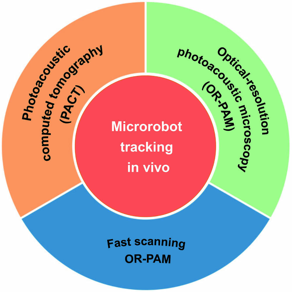
In this review, we systematically summarize the PAI principles, techniques, systems, and biomedical applications in microrobots tracking and navigation. As summarized in Fig. 1, the PAI systems including PA computed tomography (PACT), optical-resolution PA microscopy (OR-PAM), and fast scanning OR-PAM are highlighted and demonstrated from the perspective of microrobots tracking. In the future, further system integration and upgrades will continue to be necessary to enable the real PAI clinical applications.
![]()
Figure 1.Schematic summary of microrobots tracking in vivo based on PAI.
2. Photoacoustic Imaging
PAI is a new hybrid imaging technique arising from the PA effect, which is based on the target’s intrinsic absorption property[
PAI combines the advantages of pure optical and ultrasonic imaging methods, making it a unique inherently background-free detector for label-free multiscale high-resolution imaging of biological structures, ranging in size from organelles to an organism[
![]()
Figure 2.In vivo PAI from organelles to organism. (a) A typical tubular-shaped mitochondrion in mouse embryonic fibroblasts[
Based on a unique absorption spectrum, a different target can be classified by PAI via different wavelengths, making it a distinctive imaging technique for multi-contrast and multi-parameter sensing including the hemoglobin concentration (CHb)[
![]()
Figure 3.Multi-contrast and multi-parameter PAI. (a) Labeled tumor and surrounding vascular vessels[
Based on these properties, by choosing a suitable wavelength, PAI can be used to induce the simultaneous imaging of endogenous contrast agents (blood vessels) and an exogenous contrast agent (microrobots). As shown in Fig. 4, in an in vivo environment, the microrobots are actuated by a variety of external fields, such as magnetic fields, and then perform therapeutic operations at the disease site. When the microrobots start to work, PAI can be used to track the microrobots and, at the same time, image and record the feedbacks of molecules (may reflect changes of functionality) in vivo. PAI can provide high-resolution and high-contrast multiscale information of structure, morphology, function, and metabolism for biological application, which has broad application prospects in the field of biomolecular imaging.
![]()
Figure 4.PAI-trackable magnetic microswimmers. Reproduced with permission from Ref. [
Nowadays, the main research branches of PAI include PACT[
3. Photoacoustic Computed Tomography Guiding Microrobots in vivo
PACT is a reconstruction-based imaging method in PAI fields. Different from the configuration scheme of laser excitation and acoustic detection in PAM imaging[
Benefitting from the advantages of the wider FOV, video-rate imaging speed, and deeper imaging depth, PACT has demonstrated enormous potential in tumor diagnosis and therapy[
As shown in Fig. 5, our laboratory further tries to integrate plane-wave US imaging and single-shot PA imaging and has developed a video-rate dual-modal imaging system using a ring-array-based US transducer[
![]()
Figure 5.In vivo US/PACT imaging of the liver and kidney. (a) US image, bipolar PA image, and unipolar PA image at the cross section of the liver (P1) and kidney (P2); arrow 1 denotes the tracked and recorded artery blood vessel position. (b) Respiration motion time interval estimation according to the correlation coefficient calculation. (c) PA amplitude changing as a function of time at the position marked by an arrow [P1 in (a)] and its corresponding spectral analysis. Reproduced with permission from Ref. [
Besides the above-mentioned excellent imaging performance, PACT is also spectrum sensitive and free from ionizing radiation and electromagnetic interference. Therefore, PACT can be a better choice for microrobots guidance to execute specific tasks within hard-to-reach regions in vivo, such as thrombus removal, drug delivery, and tumor therapy.
The first, to the best of our knowledge, reported integration platform of the microrobotic system and PACT imaging system for investigation in vivo is from Wang’s group[
![]()
Figure 6.Microrobotic system guided by PACT in vivo. (a) Microrobots in the mouse with PA excitation and generation. (b) PACT imaging setup. (c) Enteric coating protection in the stomach. (d) CW NIR laser irradiation for micromotor release in the intestine. (e) Microrobots propulsion to the therapy region. (f) Dynamics evaluation of PACT-guided microrobots movement in the intestine. (g) Movement displacement caused by the microrobots migration. (h) Movement displacement caused by respiration. (i) Speed comparison of microrobots migration and the respiration-induced movement. Reproduced with permission from Ref. [
Precise delivery of therapeutic cells loaded by the microrobots to the targeted tumor region through the vascular region is promising in precision medicine. This therapy method can respond to cancer dynamically with few side effects and will not cause excessive immune response[
![]()
Figure 7.Microrobots imaging and navigation using developed PACT/US dual-modal system. (a) Comparison of PA signal amplitude in the left lateral lobe with and without injection microrobots clusters. The microrobots were injected through the portal vein, and the PA images were overlayed on the US images. (b) PA/US imaging guiding microrobots in the inferior vena cava of the mouse. Reproduced with permission from Ref. [
Because of the remarkable imaging performance and compatibility features, PACT imaging is attracting more and more attention in the areas of microrobot characterization, drug delivery, and tumor therapy since 2019[
4. High-Resolution Tracking by Optical-Resolution Photoacoustic Microscopy
With the PACT system, the images of the microrobots or swarm are often bright spots. Its isotropic spatial resolution of over 100 µm is not enough to see the clear shape of the microrobots around the 100 µm size. As a result, the movement of the microrobots tracked by the PACT system is shown as a few moving bright spots. Therefore, high-resolution PAI is still required to observe the shape and position of a single microrobot, especially for those with sizes less than 100 µm.
Compared with other biomedical imaging technologies that can only look at the microrobots’ trajectory, distribution, and features gathered on the tissue in a macroscopic view, OR-PAM can realize both subcellular multifunctional and robotic imaging, providing a microscopic view of microrobotic research.
Last year, our laboratory demonstrated the PAI of a single microrobot in blood, as shown in Fig. 7. The OR-PAM system in Fig. 8(a) shows that the optical excitation and ultrasonic detection in OR-PAM are aligned confocally, enabling it a micron-scale lateral resolution, which enables sub-cellular-scale features to be resolved.
![]()
Figure 8.PAI of a single microrobot in blood. (a) Optical resolution PA system. (b) High-resolution PA tracking of a single micro-rocket in the blood vessel model. Reproduced with permission from Ref. [
The main task for the microrobots is to reach the disease site within the organs. The blood vessel is the best channel for this, as the blood is circulated throughout the body. Therefore, precise tracking of a microrobot in the bloodstream is quite essential. As demonstrated in Fig. 8(b), the ∼50 µm micro-rocket robot is successfully tracked at a 3.2 µm resolution with the OR-PAM system in blood. When the micro-rocket moved in the blood vessel model, the OR-PAM acquired multiple images at different positions with clear information of the structure and depth of the single micro-rocket.
For the current system in Fig. 8(a), the real-time tracking of microrobots remains difficult to achieve due to its slow imaging speed. In vessels with high flows, only real-time tracking enables effective control for the microrobots. Therefore, developing the faster OR-PAM system will be significant to advance high-resolution PA tracking in vivo.
5. Fast Scanning OR-PAM
A single microrobot can be tracked with high resolution by employing OR-PAM. To track the moving microrobots in the vessel, we need to use a fast scanning OR-PAM with a high C-scan rate over a large FOV.
There are mainly three approaches that have been proposed to achieve a high imaging speed. Firstly, due to object inertia, a fiber-based OR-PAM system has a higher scanning speed compared to a fixed free-space OR-PAM system, because the PA probe has a smaller mass than the sample platform and easily achieves fast translation[
The galvanometer can effectively improve the scanning speed, while it cannot work in water and has a serious contradiction between FOV and sensitivity[
The water-immersible MEMS scanner and water-immersible galvanometer occupy the workspace, resulting in a smaller acoustic lens numerical aperture (NA). The voice-coil scanner is a high-speed motion platform that can achieve fast scanning without sacrificing sensitivity. It has been successfully used as the fast axis of OR-PAM, as shown in Fig. 9(a)[
![]()
Figure 9.Voice-coil-driven fast-scanning OR-PAM. (a) Schematic of the system. (b) Snapshots of single RBCs releasing oxygen in a mouse brain. (c) sO2 images without continuous visual stimulation. (d) sO2 images with 1 Hz continuous optical flashing stimulations on the left mouse eye. Reproduced with permission from Ref. [
To further improve the scanning speed and FOV, our laboratory developed a polygon scanner OR-PAM, as demonstrated in Fig. 10[
![]()
Figure 10.Polygon-scanning fast OR-PAM. (a) Schematic of the system. (b) sO2 image of the mouse ear; C-scan time is ∼5 s. (c) Flowing iron particle tracking. Reproduced with permission from Ref. [
![]()
Figure 11.Single-breath-hold PACT system for breast cancer diagnosis and screening. (a) Perspective cut-away view of patient bed and optical components of the system. (b) Data acquisition components of the system. Four sets of 128-channel data acquisition systems were mapping a custom-built 512-element ring-array transducer. Reproduced with permission from Ref. [
Finally, we summarized some typical fast scanning OR-PAMs’ imaging speed and scanning range in Table 1, offering alternative methods for high-resolution tracking of microrobots in vivo.
| Methods | B-scan Rate (Hz) | B-scan Range (mm) |
|---|---|---|
| Galvanometer[ | 1800/100 | 0.1/6 |
| Water-immersible galvanometer[ | 500 | >2.4 |
| Voice-coil[ | 40 | ∼5 |
| Single-axis water-immersible MEMS[ | 400 | >3 |
| Dual-axis water-immersible MEMS[ | 5 | 9 |
| Polygon mirror[ | ∼500 | ∼12 |
Table 1. Scanning Speed and Range of Fast-Scanning PAM Systems
The water-immersible galvanometer, water-immersible MEMS scanner, and polygon scanner have higher scanning speeds compared with other reported scanners. It is possible for them to achieve real-time tracking of microrobots. Among them, polygon-scanning fast OR-PAM shows outstanding advantages in the FOV. For example, with the same B-scan rate of 500 Hz, the B-scan range of the water-immersible galvanometer and MEMS scanner only reaches ∼4 mm, while the polygon mirror scanner reaches as high as 12 mm. To achieve a 12 mm × 12 mm FOV, the water-immersible galvanometer and MEMS-scanning OR-PAM have to adopt an imaging stitching method due to the limited B-scan range, three times that of polygon-scanning OR-PAM to achieve the same FOV. Therefore, the polygon scanner is a potential tool for broadening the application of OR-PAM in microrobots tracking.
Overall, this review details the biomedical applications of PAI for microrobots tracking in terms of the different PAI systems and techniques. To compare these imaging systems more clearly and to identify their range of applications, Table 2 is presented to summarize the three types of highlighted PAI systems, including SIP-PACT, OR-PAM, and polygon-scanning fast OR-PAM. For PACT, its advantages are the large imaging penetration depth and the real-time imaging capability, which can be used for whole-body dynamics and function imaging for small animals. Therefore, for real-time microrobots tracking in the deep tissue of the living body, PACT would be the best option. However, the limited resolution makes it difficult to track an individual microrobot less than 100 µm. At this point, the OR-PAM compensates well for this deficiency, as its resolution can reach below 10 µm. For the high-resolution microrobots tracking in epidermal blood vessels or tissue, OR-PAM could be used as a priority. Moreover, the polygon-scanning fast OR-PAM also demonstrates fast imaging capabilities, providing an excellent option for high-resolution real-time imaging for microrobots tracking.
| PAI System & Techniques | Resolution | Imaging Depth | Advantages | Applications |
|---|---|---|---|---|
| SIP-PACT[ | 125 µm | 48 mm | Whole-body dynamics and function imaging for small animals | Real-time tracking of microrobots in vivo |
| OR-PAM[ | 3.2 µm | 1 mm | High-resolution imaging | High-resolution microrobots tracking in epidermal blood vessels or tissue |
| Polygon-scanning fast OR-PAM[ | ∼6.3 µm | 0.97 mm | Fast and high-resolution imaging | Real-time and high-resolution microrobots tracking in the epidermis |
Table 2. Summary of PAI Systems in the Review for Microrobots Tracking
Currently, all microrobots tracking using PAI is limited to in vitro or small animal bodies. More time is needed for the real application of microrobots tracking to the human body. PA technology for whole-body imaging of the human body is not yet mature enough, given its limited penetration depth. Therefore, PAI techniques and systems need breakthroughs first. Then, the integration of the microrobots control equipment and imaging systems will be the next step towards in vivo clinical application of microrobots.
6. Perspectives on Future Clinical Applications
At the current stage, PAI has not been applied to clinical tests and imaging. In contrast, US, X-ray, and MRI imaging techniques have all developed into sophisticated equipment and are used in major hospitals. Despite many current technical challenges, experts in the field of PAI have never stopped pursuing the commercialization of PAI technology. For example, in 2018, Wang’s group designed the single-breath-hold PACT system for breast cancer diagnosis, as shown in Fig. 11[
To further promote clinical applications of PACT imaging, the following areas could be highlighted for research: developing new image reconstruction algorithms to improve the quality of images; integrating with different imaging modalities, such as US imaging, fluorescence imaging, and optical coherence tomography, to provide complementary information; developing new scanning systems for large area real-time imaging; and introducing novel PA excitation modes and systems to improve imaging resolution.
For the OR-PAM system, high resolution is an inherent advantage in superficial tissue imaging. However, its disadvantages of non-real-time imaging cannot be ignored. Therefore, fast OR-PAM imaging would be of great interest for clinical applications. In addition, increasing the imaging depth of the OR-PAM system is necessary and extremely challenging.
For in vivo tracking, microrobots within deep tissues such as human organs would be better suited to a PACT system guided robotic navigation for in situ drug transport and therapy. For microrobots in subcutaneous vessels or tissues, OR-PAM would be the superior choice, due to the improved high resolution. For the time being, the most efficient way of driving robots in the living body is magnetic actuation. The integration of a robotic magnetic actuation system with the PAI system will take the future of robotic clinical applications to new heights.
In conclusion, PAI provides a comprehensive and superior biomedical imaging modality for microrobots navigation in living bodies. Future advances in PAI technology and the use of PAI in clinical applications will greatly facilitate the realization of robot-assisted medicine.
References
[1] J. Li, B. E.-F. de Ávila, W. Gao, L. Zhang, J. Wang. Micro/nanorobots for biomedicine: delivery, surgery, sensing, and detoxification. Sci. Robot., 2, eaam6431(2017).
[2] B. E.-F. de Ávila, P. Angsantikul, J. Li, M. Angel Lopez-Ramirez, D. E. Ramírez-Herrera, S. Thamphiwatana, C. Chen, J. Delezuk, R. Samakapiruk, V. Ramez, L. Zhang, J. Wang. Micromotor-enabled active drug delivery for in vivo treatment of stomach infection. Nat. Commun., 8, 272(2017).
[3] J. Li, X. Li, T. Luo, R. Wang, C. Liu, S. Chen, D. Li, J. Yue, S. H. Cheng, D. Sun. Development of a magnetic microrobot for carrying and delivering targeted cells. Sci. Robot., 3, eaat8829(2018).
[4] X. Z. Chen, B. Jang, D. Ahmed, C. Hu, C. De Marco, M. Hoop, F. Mushtaq, B. J. Nelson, S. Pané. Small-scale machines driven by external power sources. Adv. Mater., 30, 1705061(2018).
[5] Y. Wu, T. Si, J. Shao, Z. Wu, Q. He. Near-infrared light-driven Janus capsule motors: fabrication, propulsion, and simulation. Nano Res., 9, 3747(2016).
[6] H. Zeng, P. Wasylczyk, C. Parmeggiani, D. Martella, M. Burresi, D. S. Wiersma. Light-fueled microscopic walkers. Adv. Mater., 27, 3883(2015).
[7] S. Tottori, L. Zhang, F. Qiu, K. K. Krawczyk, A. Franco-Obregón, B. J. Nelson. Magnetic helical micromachines: fabrication, controlled swimming, and cargo transport. Adv. Mater., 24, 811(2012).
[8] C. Peters, M. Hoop, S. Pané, B. J. Nelson, C. Hierold. Degradable magnetic composites for minimally invasive interventions: device fabrication, targeted drug delivery, and cytotoxicity tests. Adv. Mater., 28, 533(2016).
[9] W. Gao, R. Dong, S. Thamphiwatana, J. Li, W. Gao, L. Zhang, J. Wang. Artificial micromotors in the mouse’s stomach: a step toward in vivo use of synthetic motors. ACS Nano., 9, 117(2015).
[10] D. Li, Y. Liu, Y. Yang, Y. Shen. A fast and powerful swimming microrobot with a serrated tail enhanced propulsion interface. Nanoscale, 10, 19673(2018).
[11] V. Magdanz, S. Sanchez, O. G. Schmidt. Development of a sperm-flagella driven micro-bio-robot. Adv. Mater., 25, 6581(2013).
[12] B. Esteban-Fernández de Ávila, P. Angsantikul, J. Li, W. Gao, L. Zhang, J. Wang. Micromotors go in vivo: from test tubes to live animals. Adv. Funct. Mater., 28, 1705640(2018).
[13] X. Yan, Q. Zhou, M. Vincent, Y. Deng, J. Yu, J. Xu, T. Xu, T. Tang, L. Bian, Y. X. J. Wang, K. Kostarelos, L. Zhang. Multifunctional biohybrid magnetite microrobots for imaging-guided therapy. Sci. Robot., 2, eaaq1155(2017).
[14] B. Wang, K. F. Chan, K. Yuan, Q. Wang, X. Xia, L. Yang, H. Ko, Y. J. Wang, J. Jao, Y. Sung, P. Wai, Y. Chiu, L. Zhang. Endoscopy-assisted magnetic navigation of biohybrid soft microrobots with rapid endoluminal delivery and imaging. Sci. Robot., 6, eabd2813(2021).
[15] Q. Wang, K. F. Chan, K. Schweizer, X. Du, D. Jin, S. C. H. Yu, B. J. Nelson, L. Zhang. Ultrasound Doppler-guided real-time navigation of a magnetic microswarm for active endovascular delivery. Sci. Adv., 7, eabe5914(2021).
[16] Q. Wang, L. Zhang. External power-driven microrobotic swarm: from fundamental understanding to imaging-guided delivery. ACS Nano., 15, 149(2021).
[17] Q. Wang, L. Zhang. Ultrasound imaging and tracking of micro/nanorobots: from individual to collectives. IEEE Open J. Nanotechnol., 1, 6(2020).
[18] Q. Wang, L. Yang, J. Yu, P. W. Y. Chiu, Y. P. Zheng, L. Zhang. Real-time magnetic navigation of a rotating colloidal microswarm under ultrasound guidance. IEEE Trans. Biomed. Eng., 67, 3403(2020).
[19] S. Jeong, H. Choi, C. Lee, G. Go, D. S. Sim, K. S. Lim, M. H. Jeong, S. Y. Ko, J. Park, S. Park. Therapeutic intravascular microrobot through compensation of resistance and mutual inductance in electromagnetic actuation system. Int. J. Control. Autom. Syst., 13, 1465(2015).
[20] S. Pané, J. Puigmartí-Luis, C. Bergeles, X.-Z. Chen, E. Pellicer, J. Sort, V. Počepcová, A. Ferreira, B. J. Nelson. Imaging technologies for biomedical micro- and nanoswimmers. Adv. Mater. Technol., 4, 1800575(2019).
[21] M. Medina-Sánchez, O. G. Schmidt. Medical microbots need better imaging and control. Nature, 545, 406(2017).
[22] D. Li, C. Liu, Y. Yang, L. Wang, Y. Shen. Micro-rocket robot with all-optic actuating and tracking in blood. Light Sci. Appl., 9, 84(2020).
[23] T. Wei, J. Liu, D. Li, S. Chen, Y. Zhang, J. Li, L. Fan, Z. Guan, C. Lo, L. Wang, K. Man, D. Sun. Development of magnet-driven and image-guided degradable microrobots for the precise delivery of engineered stem cells for cancer therapy. Small, 16, 1906908(2020).
[24] L. V. Wang, J. Yao. A practical guide to photoacoustic tomography in the life sciences. Nat. Methods, 13, 627(2016).
[25] S. Manohar, D. Razansky. Photoacoustics: a historical review. Adv. Opt. Photon., 8, 586(2016).
[26] M. Xu, L. V. Wang. Photoacoustic imaging in biomedicine. Rev. Sci. Instrum., 77, 041101(2006).
[27] T. Feng, Y. Zhu, Y. Xie, D. Ta, J. Yuan, Q. Cheng. Feasibility study for bone health assessment based on photoacoustic imaging method. Chin. Opt. Lett., 18, 121704(2020).
[28] A. Danielli, K. I. Maslov, A. Garcia-Uribe, A. M. Winkler, C. Li, L. Wang, Y. Chen, G. W. Dorn, L. V. Wang. Label-free photoacoustic nanoscopy. J. Biomed. Opt., 19, 086006(2014).
[29] C. Liu, Y. Liang, L. Wang. Optical-resolution photoacoustic microscopy of oxygen saturation with nonlinear compensation. Biomed. Opt. Express, 10, 3061(2019).
[30] L. Lin, P. Hu, J. Shi, C. M. Appleton, K. Maslov, L. Li, R. Zhang, L. V. Wang. Single-breath-hold photoacoustic computed tomography of the breast. Nat. Commun., 9, 2352(2018).
[31] Y. Matsumoto, Y. Asao, A. Yoshikawa, H. Sekiguchi, M. Takada, M. Furu, S. Saito, M. Kataoka, H. Abe, T. Yagi, K. Togashi, M. Toi. Label-free photoacoustic imaging of human palmar vessels: a structural morphological analysis. Sci. Rep., 8, 786(2018).
[32] A. P. Jathoul, J. Laufer, O. Ogunlade, B. Treeby, B. Cox, E. Zhang, P. Johnson, A. R. Pizzey, B. Philip, T. Marafioti, M. F. Lythgoe, R. B. Pedley, M. A. Pule, P. Beard. Deep in vivo photoacoustic imaging of mammalian tissues using a tyrosinase-based genetic reporter. Nat. Photon., 9, 239(2015).
[33] J. Chen, Y. Zhang, X. Li, J. Zhu, D. Li, S. Li, C.-S. Lee, L. Wang. Confocal visible/NIR photoacoustic microscopy of tumors with structural, functional, and nanoprobe contrasts. Photon. Res., 8, 1875(2020).
[34] C. Liu, Y. Liang, L. Wang. Single-shot photoacoustic microscopy of hemoglobin concentration, oxygen saturation, and blood flow in sub-microseconds. Photoacoustics, 17, 100156(2020).
[35] C. Liu, J. Chen, Y. Zhang, J. Zhu, L. Wang. Five-wavelength optical-resolution photoacoustic microscopy of blood and lymphatic vessels. Adv. Photon., 3, 016002(2021).
[36] L. Lin, J. Yao, L. Li, L. V. Wang. In vivo photoacoustic tomography of myoglobin oxygen saturation. J. Biomed. Opt., 21, 061002(2015).
[37] B. Wang, J. L. Su, J. Amirian, S. H. Litovsky, R. Smalling, S. Emelianov. Detection of lipid in atherosclerotic vessels using ultrasound-guided spectroscopic intravascular photoacoustic imaging. Opt. Express, 18, 4889(2010).
[38] C. Yin, G. Wen, C. Liu, B. Yang, S. Lin, J. Huang, P. Zhao, S. H. D. Wong, K. Zhang, X. Chen, G. Li, X. Jiang, J. Huang, K. Pu, L. Wang, L. Bian. Organic semiconducting polymer nanoparticles for photoacoustic labeling and tracking of stem cells in the second near-infrared window. ACS Nano., 12, 12201(2018).
[39] Y. Dai, X. Yu, J. Wei, F. Zeng, Y. Li, X. Yang, Q. Luo, Z. Zhang. Metastatic status of sentinel lymph nodes in breast cancer determined with photoacoustic microscopy via dual-targeting nanoparticles. Light Sci. Appl., 9, 164(2020).
[40] H. Fang, K. Maslov, L. V. Wang. Photoacoustic Doppler effect from flowing small light-absorbing particles. Phys. Rev. Lett., 99, 184501(2007).
[41] J. Yao, K. I. Maslov, Y. Shi, L. A. Taber, L. V. Wang. In vivo photoacoustic imaging of transverse blood flow by using Doppler broadening of bandwidth. Opt. Lett., 35, 1419(2010).
[42] L. Xie, X. Pang, X. Yan, Q. Dai, H. Lin, J. Ye, Y. Cheng, Q. Zhao, X. Ma, X. Zhang, G. Liu, X. Chen. Photoacoustic imaging-trackable magnetic microswimmers for pathogenic bacterial infection treatment. ACS Nano., 14, 2880(2020).
[43] L. Li, L. Zhu, C. Ma, L. Lin, J. Yao, L. Wang, K. Maslov, R. Zhang, W. Chen, J. Shi, L. V. Wang. Single-impulse panoramic photoacoustic computed tomography of small-animal whole-body dynamics at high spatiotemporal resolution. Nat. Biomed. Eng., 1, 0071(2017).
[44] P. Zhang, L. Li, L. Lin, J. Shi, L. V. Wang. In vivo superresolution photoacoustic computed tomography by localization of single dyed droplets. Light Sci. Appl., 8, 36(2019).
[45] W. Choi, C. Kim. Toward in vivo translation of super-resolution localization photoacoustic computed tomography using liquid-state dyed droplets. Light Sci. Appl., 8, 57(2019).
[46] J. Yao, L. Wang, J. M. Yang, K. I. Maslov, T. T. W. Wong, L. Li, C. H. Huang, J. Zou, L. V. Wang. High-speed label-free functional photoacoustic microscopy of mouse brain in action. Nat. Methods, 12, 407(2015).
[47] Y. Li, T. T. W. Wong, J. Shi, H. C. Hsu, L. V. Wang. Multifocal photoacoustic microscopy using a single-element ultrasonic transducer through an ergodic relay. Light Sci. Appl., 9, 135(2020).
[48] M. Chen, H. J. Knox, Y. Tang, W. Liu, L. Nie, J. Chan, J. Yao. Simultaneous photoacoustic imaging of intravascular and tissue oxygenation. Opt. Lett., 44, 3773(2019).
[49] Y. Liang, L. Jin, B.-O. Guan, L. Wang. 2 MHz multi-wavelength pulsed laser for functional photoacoustic microscopy. Opt. Lett., 42, 1452(2017).
[50] J. Kim, J. Y. Kim, S. Jeon, J. W. Baik, S. H. Cho, C. Kim. Super-resolution localization photoacoustic microscopy using intrinsic red blood cells as contrast absorbers. Light Sci. Appl., 8, 103(2019).
[51] E. Vienneau, W. Liu, J. Yao. Dual-view acoustic-resolution photoacoustic microscopy with enhanced resolution isotropy. Opt. Lett., 43, 4413(2018).
[52] P. K. Upputuri, M. Pramanik. Recent advances toward preclinical and clinical translation of photoacoustic tomography: a review. J. Biomed. Opt., 22, 041006(2016).
[53] L. V. Wang, S. Hu. Photoacoustic tomography: in vivo imaging from organelles to organs. Science, 335, 1458(2012).
[54] J. Yao, A. A. Kaberniuk, L. Li, D. M. Shcherbakova, R. Zhang, L. Wang, G. Li, V. V. Verkhusha, L. V. Wang. Multiscale photoacoustic tomography using reversibly switchable bacterial phytochrome as a near-infrared photochromic probe. Nat. Methods, 13, 67(2015).
[55] X. Wang, S. Yang. Imaging of human wrist joint by a flexible-transducer-based morphological-adaptive photoacoustic tomography: a feasibility study. Chin. Opt. Lett., 17, 091701(2019).
[56] G. Li, L. Li, L. Zhu, J. Xia, L. V. Wang. Multiview Hilbert transformation for full-view photoacoustic computed tomography using a linear array. J. Biomed. Opt., 20, 066010(2015).
[57] L. Wang, G. Li, J. Xia, L. V. Wang. Ultrasonic-heating-encoded photoacoustic tomography with virtually augmented detection view. Optica, 2, 307(2015).
[58] L. Lin, P. Hu, X. Tong, S. Na, R. Cao, X. Yuan, D. C. Garrett, J. Shi, K. Maslov, L. V. Wang. High-speed three-dimensional photoacoustic computed tomography for preclinical research and clinical translation. Nat. Commun., 12, 882(2021).
[59] K. Huda, C. Wu, J. G. Sider, C. L. Bayer. Spherical-view photoacoustic tomography for monitoring in vivo placental function. Photoacoustics, 20, 100209(2020).
[60] Y. Zhang, L. Wang. Video-rate ring-array ultrasound and photoacoustic tomography. IEEE Trans. Med. Imaging., 39, 4369(2020).
[61] H. Estrada, A. Ozbek, J. Robin, S. Shoham, D. Razansky. Spherical array system for high-precision transcranial ultrasound stimulation and optoacoustic imaging in rodents. IEEE Trans. Ultrason. Ferroelectr. Freq. Control., 68, 107(2021).
[62] M. Heijblom, W. Steenbergen, S. Manohar. Clinical photoacoustic breast imaging: the Twente experience. IEEE Pulse, 6, 42(2015).
[63] F. Zheng, X. Zhang, C. T. Chiu, B. L. Zhou, K. K. Shung, H. F. Zhang, S. Jiao. Laser-scanning photoacoustic microscopy with ultrasonic phased array transducer. Biomed. Opt. Express, 3, 2694(2012).
[64] S. Li, Q. Deng, Y. Zhang, X. Li, G. Wen, X. Cui, Y. Wan, Y. Huang, J. Chen, Z. Liu, L. Wang, C. S. Lee. Rational design of conjugated small molecules for superior photothermal theranostics in the NIR-II biowindow. Adv. Mater., 32, 2001146(2020).
[65] G. Wen, X. Li, Y. Zhang, X. Han, X. Xu, C. Liu, K. W. Y. Chan, C. S. Lee, C. Yin, L. Bian, L. Wang. Effective phototheranostics of brain tumor assisted by near-infrared-II light-responsive semiconducting polymer nanoparticles. ACS Appl. Mater. Interfaces., 12, 33492(2020).
[66] M. Zha, X. Lin, J. S. Ni, Y. Li, Y. Zhang, X. Zhang, L. Wang, K. Li. An ester-substituted semiconducting polymer with efficient nonradiative decay enhances NIR-II photoacoustic performance for monitoring of tumor growth. Angew. Chemie–Int. Ed., 59, 23268(2020).
[67] J. Zhang, G. Wen, W. Wang, K. Cheng, Q. Guo, S. Tian, C. Liu, H. Hu, Y. Zhang, H. Zhang, L. Wang, H. Sun. Controllable cleavage of C–N bond-based fluorescent and photoacoustic dual-modal probes for the detection of H2S in living mice. ACS Appl. Bio Mater., 4, 2020(2021).
[68] J. Xia, C. Kim, J. F. Lovell. Opportunities for photoacoustic-guided drug delivery. Curr. Drug Targets., 16, 571(2015).
[69] N. Gandhi, M. Allard, S. Kim, P. Kazanzides, M. A. L. Bell. Photoacoustic-based approach to surgical guidance performed with and without a da Vinci robot. J. Biomed. Opt., 22, 121606(2017).
[70] Z. Wu, L. Li, Y. Yang, P. Hu, Y. Li, S. Y. Yang, L. V. Wang, W. Gao. A microrobotic system guided by photoacoustic computed tomography for targeted navigation in intestines in vivo. Sci. Robot, 4, eaax0613(2019).
[71] L. Labanieh, R. G. Majzner, C. L. Mackall. Programming CAR-T cells to kill cancer. Nat. Biomed. Eng., 2, 377(2018).
[72] A. Aziz, M. Medina-Sánchez, J. Claussen, O. G. Schmidt. Real-time optoacoustic tracking of single moving micro-objects in deep phantom and ex vivo tissues. Nano Lett., 19, 6612(2019).
[73] Y. Yan, W. Jing, M. Mehrmohammadi. Photoacoustic imaging to track magnetic-manipulated micro-robots in deep tissue. Sensors, 20, 2816(2020).
[74] G. S. Jeng, M. L. Li, M. W. Kim, S. J. Yoon, J. J. Pitre, D. S. Li, I. Pelivanov, M. O’Donnell. Real-time interleaved spectroscopic photoacoustic and ultrasound (PAUS) scanning with simultaneous fluence compensation and motion correction. Nat. Commun., 12, 716(2021).
[75] H. Su. Optical-resolution photoacoutic microscopy(2010).
[76] K. Maslov, H. F. Zhang, S. Hu, L. V. Wang. Optical-resolution photoacoustic microscopy for in vivo imaging of single capillaries. Opt. Lett., 33, 929(2008).
[77] S. Hu, K. Maslov, L. V. Wang. Second-generation optical-resolution photoacoustic microscopy with improved sensitivity and speed. Opt. Lett., 36, 1134(2011).
[78] Y. Liang, J.-W. Liu, L. Jin, B.-O. Guan, L. Wang. Fast-scanning photoacoustic microscopy with a side-looking fiber optic ultrasound sensor. Biomed. Opt. Express, 9, 5809(2018).
[79] B. Rao, K. Maslov, A. Danielli, R. Chen, K. K. Shung, Q. Zhou, L. V. Wang. Real-time four-dimensional optical-resolution photoacoustic microscopy with Au nanoparticle-assisted subdiffraction-limit resolution. Opt. Lett., 36, 1137(2011).
[80] W. Qin, T. Jin, H. Guo, L. Xi. Large-field-of-view optical resolution photoacoustic microscopy. Opt. Express, 26, 4271(2018).
[81] C. Zhang, H. Zhao, S. Xu, N. Chen, K. Li, X. Jiang, L. Liu, Z. Liu, L. Wang, K. K. Y. Wong, J. Zou, C. Liu, L. Song. Multiscale high-speed photoacoustic microscopy based on free-space light transmission and a MEMS scanning mirror. Opt. Lett., 45, 4312(2020).
[82] J. Lee, S. Han, D. Seong, J. Lee, S. Park, R. Eranga Wijesinghe, M. Jeon, J. Kim. Fully waterproof two-axis galvanometer scanner for enhanced wide-field optical-resolution photoacoustic microscopy. Opt. Lett., 45, 865(2020).
[83] L. Wang, K. Maslov, L. V. Wang. Single-cell label-free photoacoustic flowoxigraphy in vivo. Proc. Natl. Acad. Sci. U. S. A., 110, 5759(2013).
[84] L. Wang, K. Maslov, J. Yao, B. Rao, L. V. Wang. Fast voice-coil scanning optical-resolution photoacoustic microscopy. Opt. Lett., 36, 139(2011).
[85] J. Chen, Y. Zhang, L. He, Y. Liang, L. Wang. Wide-field polygon-scanning photoacoustic microscopy of oxygen saturation at 1-MHz A-line rate. Photoacoustics., 20, 100195(2020).
[86] J. Y. Kim, C. Lee, K. Park, S. Han, C. Kim. High-speed and high-SNR photoacoustic microscopy based on a galvanometer mirror in non-conducting liquid. Nat. Publ. Gr., 6, 34803(2016).
[87] J. Y. Kim, C. Lee, K. Park, G. Lim, C. Kim. Fast optical-resolution photoacoustic microscopy using a 2-axis water-proofing MEMS scanner. Sci. Rep., 5, 7932(2015).
[88] B. Lan, W. Liu, Y. Wang, J. Shi, Y. Li, S. Xu, H. Sheng, Q. Zhou, J. Zou, U. Hoffmann, W. Yang, J. Yao. High-speed widefield photoacoustic microscopy of small-animal hemodynamics. Biomed. Opt. Express, 9, 4689(2018).

Set citation alerts for the article
Please enter your email address
© Copyright 2018-2021 | Chinese Laser Press. All Rights Reserved 沪ICP备15018463号-20