
Pengpeng Ding, Yunhua Yao, Dalong Qi, Chengshuai Yang, Fengyan Cao, Yilin He, Jiali Yao, Chengzhi Jin, Zhengqi Huang, Li Deng, Lianzhong Deng, Tianqing Jia, Jinyang Liang, Zhenrong Sun, Shian Zhang. Single-shot spectral-volumetric compressed ultrafast photography[J]. Advanced Photonics, 2021, 3(4): 045001
- Advanced Photonics
- Vol. 3, Issue 4, 045001 (2021)
Abstract
Keywords
1 Introduction
Acquiring the spatial , temporal (), and spectral () information of an object is very important in natural science exploration. Multi-dimensional optical imaging, as a visualization method, can provide information covering the space, time, and spectrum.1 So far, multi-dimensional optical imaging has played an irreplaceable role in exploring the unknown world and decrypting natural mysteries such as light–matter interactions,2 light scattering in tissues,3 and physical or biochemical reactions.4
To break the detection limitation of the existing snapshot multi-dimensional optical imaging in the whole spatial, temporal, and spectral dimensions, we develop a spectral-volumetric compressed ultrafast photography (SV-CUP) technique to realize the spatial–temporal–spectral 5D imaging of the dynamic scenes. Here SV-CUP combines our previous HCUP and ToF-CUP.21 HCUP captures the spatial–temporal–spectral 4D information of the dynamic scenes, and ToF-CUP extracts the spatial 3D information of the dynamic scenes. The 3D information in ToF-CUP is coupled to the 4D information in HCUP and forms 5D information by image processing. Using SV-CUP, we experimentally demonstrate the spectrally resolved photoluminescent dynamics of a 3D mannequin coated with CdSe quantum dots, which confirms the reliability of SV-CUP.
2 SV-CUP’s Configuration and Principle
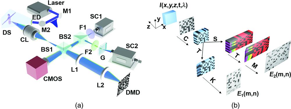
A schematic diagram of SV-CUP is shown in Fig. 1(a). A laser pulse (400-nm central wavelength, 50-fs pulse duration) transmits through an engineered diffuser (Thorlabs, ED1-S20-MD) and then irradiates on a 3D object. The laser pulse excites the matter on the surface of the 3D object, and the laser-induced optical signal (such as fluorescence) is collected by a camera lens (Nikon, AF Nikkor 35 mm), together with the backscattered optical signal of the laser pulse from the surface of the 3D object. Here the laser-induced optical signal is used to study the dynamic behavior of the laser–matter interaction, and the backscattered optical signal is used to obtain the spatial structure of the 3D object. Both optical signals are divided into two components by a beam splitter (BS1). One is reflected to an external CMOS camera (Andor, ZYLA 4.2), and the other is imaged onto a digital micromirror device (DMD, Texas Instruments, DLP Light Crafter 3000) through a imaging system. The two optical signals are encoded with a static pseudorandom binary pattern on the DMD and then retroreflected through the same imaging system. The two encoded optical signals are divided into two components by another beam splitter (BS2) again, one goes into an HCUP subsystem,18 and the other enters a ToF-CUP subsystem.21 In ToF-CUP, the laser-induced optical signal is filtered by a bandpass filter, and only the backscattered optical signal is sent into a streak camera SC1 (XIOPM, 5200). In HCUP, the backscattered optical signal is filtered, and the laser-induced optical signal is sent to a grating (Thorlabs, GT25-03) for horizontal deflection and then to another streak camera SC2 (Hamamatsu, C7700) for vertical deflection and integral imaging. The external CMOS camera and the two streak cameras are precisely synchronized by a digital delay generator (Stanford Research Systems, DG645). In this experiment, the unencoded and undeflected image measured by the external CMOS camera is used to provide the spatial and intensity threshold constraint in the subsequent image reconstruction.22
Sign up for Advanced Photonics TOC. Get the latest issue of Advanced Photonics delivered right to you!Sign up now
![]()
Figure 1.SV-CUP’s configuration and principle. (a) System configuration of SV-CUP: M1 and M2, mirrors; ED, engineered diffuser; DS, dynamic scene; CL, camera lens; BS1 and BS2, beam splitters (reflection/transmission: 50/50); F1 and F2, filters; G, diffraction grating; L1 and L2, lenses; DMD, digital micromirror device; CMOS, complementary metal-oxide semiconductor camera; and SC1 and SC2, streak cameras. (b) Working principle of SV-CUP: C, spatial encoding operator; T, temporal shearing operator; K, spatial-temporal integration operator; S, spectral shearing operator; and M, spatial–temporal–spectral integration operator.
Mathematically, the SV-CUP system contains two imaging subsystems, i.e., HCUP and ToF-CUP. As can be seen in Fig. 1(b), the original 5D dynamic scene , involving spatial 3D, temporal 1D, and spectral 1D information, is first encoded and then divided into two components for imaging: ToF-CUP is used to capture the spatial 3D information21 and HCUP is used to record the spatial–temporal–spectral 4D information.18
In ToF-CUP, the backscattered optical signal is sheared in the temporal domain. According to the time of received photons and the intensity reflectivity of the 3D object, the backscattered optical signal can be described as
To recover the spatial 3D information, i.e., , an augmented Lagrangian (AL) algorithm based on compressed sensing is employed to solve the minimization problem,18 and it is given by
In HCUP, the laser-induced optical signal (such as fluorescence) is sheared in both the temporal and spectral domains. Similarly, the compressed image recorded by HCUP can be written as
To retrieve the spatial–temporal–spectral 4D information, i.e., , the AL algorithm is also used to solve the inverse problem of Eq. (4) and it is given by
Based on Eqs. (3) and (5), in ToF-CUP and in HCUP can be individually reconstructed; here the penalty parameters are 0.25 and 0.001 in Eqs. (3) and (5), respectively. By coupling to , the spatial–temporal–spectral 5D information, i.e., , can be extracted by image processing. According to the time relation between ToF-CUP and HCUP, the coupling operation can be expressed as
3 SV-CUP’s Depth Resolution Characterization
SV-CUP is composed of ToF-CUP and HCUP, thus the technical index of SV-CUP is determined by ToF-CUP and HCUP. Only HCUP provides the temporal and spectral information, and therefore determines the temporal and spectral frame intervals of SV-CUP. The spatial resolutions in the and directions are related to both ToF-CUP and HCUP, but HCUP has the lower spatial resolutions due to a higher data compressed ratio compared to ToF-CUP, thus the spatial resolutions in the and directions of SV-CUP are also decided by HCUP. However, the spatial resolution in the direction is only related to ToF-CUP, and thus ToF-CUP determines the spatial resolution in the direction of SV-CUP. In our previous work, the related technical parameters of HCUP have been characterized.18 The spatial resolutions in the and directions are, respectively, 0.39 and 0.35 mm with an field of view (FOV), corresponding to 1.26 and 1.41 line pairs per millimeter (lp/mm) in our previous report. The temporal frame interval is 2 ps, and the spectral frame interval is 1.72 nm. However, the spatial resolution in the direction (i.e., depth resolution) of ToF-CUP needs to be characterized here.
The experimental arrangement for characterizing the depth resolution of SV-CUP is shown in Fig. 2(a). A ladder-structured model is used as the measured object, and an ultrashort laser pulse irradiates this ladder-structured model. The backscattered optical signal from these ladders at different heights is collected by SV-CUP. The size of the ladder-structured model is shown in Fig. 2(b). Based on these sizes, the temporal intervals on these ladders can be calculated as, respectively, 10, 20, 30, and 40 ps, and the total time window is 100 ps. Three representative reconstructed images are shown in Fig. 2(c). As can be seen, the first two ladders are simultaneously observed at the time of 8 ps, which are indistinguishable. However, at the time of 32 ps, the first two ladders completely disappear, and only the third ladder is observed. Similarly, only the fifth ladder appears at the time of 104 ps. By these experimental observations, the height difference of 3 mm between the second and third ladders can be determined as the depth resolution of SV-CUP. The reconstructed 3D ladder-structured model is given in Fig. 2(d), which is consistent with the actual object in the size. Here the zero position in the direction refers to the green dashed line in Fig. 2(b), and the height difference of the first two ladders cannot be perfectly retrieved, which is due to the limitation of depth resolution.
![]()
Figure 2.SV-CUP’s depth resolution characterization: (a) schematic diagram of the experimental setup; (b) the actual size of the ladder-structured model along the
4 SV-CUP’s 5D Imaging
To demonstrate the excellent performance of SV-CUP in spatial–temporal–spectral 5D imaging, we used SV-CUP to measure the photoluminescent dynamics of a 3D mannequin coated with CdSe quantum dots, and the experimental arrangement is shown in Fig. 3(a). A strong optical absorbance of CdSe is at the wavelength of 400 nm,23,24 which corresponds to the laser central wavelength. The reconstructed data cube of the 3D mannequin is shown in Fig. 3(b). One can see that the reconstructed mannequin is the same as the real mannequin in the spatial distribution. Figure 3(c) shows the reconstructed images of the 3D mannequin at some representative times and wavelengths. Obviously, the fluorescence intensity evolutions in both the temporal and spectral dimensions can be clearly observed. In the spectral dimension, the central wavelength of the fluorescence spectrum is 532 nm, and the whole spectral range is about 64 nm. In the temporal dimension, the right hand, body, and left hand of the 3D mannequin appear in turn due to the difference in the spatial depth, and the whole mannequin is observed at the time of 480 ps. All the fluorescence intensities at these different wavelengths almost reach the maximal values after excitation for about 8 ns, and the duration of the whole photoluminescent process is about 50 ns. To verify the reconstruction accuracy in the temporal and spectral dimensions, we calculate the fluorescence intensities in the temporal and spectral domains from Fig. 3(c) and compare them with the experimental results by other measurement methods. Here the fluorescence intensity in the temporal domain (i.e., photoluminescent dynamics) is measured by a streak camera, and the fluorescence intensity in the spectral domain (i.e., fluorescence spectrum) is measured by a spectrometer. Both the calculated and experimental results are shown in Figs. 3(d) and 3(e) for comparison. Obviously, the reconstruction results are in good agreement with the experimental measurements. Additionally, we also extract the time-resolved fluorescence spectroscopy from Fig. 3(c), and the calculated result is shown in Fig. 3(f). All the fluorescence spectral components have the same temporal evolution behavior, which shows a fast increase and then a slow decrease in intensity. For intuitive observation, we calculate the fluorescence lifetimes at some selected spectral components from Fig. 3(f), as shown in Fig. 3(g). It can be seen that these fluorescence spectral components have similar lifetimes, which well illustrates that all the fluorescence spectral components come from the relaxation of the same excited states in CdSe quantum dots.
![]()
Figure 3.SV-CUP’s 5D imaging: (a) experimental arrangement for imaging the photoluminescent dynamics of a 3D mannequin coated with CdSe quantum dots; (b) reconstructed data cube of the 3D mannequin; (c) selected reconstructed images of the 3D mannequin at some representative times and wavelengths; (d) photoluminescent dynamics calculated from (c) (blue line) and measured by a streak camera (red line); (e) fluorescence spectrum calculated from (c) (blue line) and measured by a spectrometer (red line); (f) time-resolved spectroscopy extracted from (c); and (g) calculated fluorescence lifetimes at some selected spectral components (
As shown in Fig. 3, SV-CUP demonstrates a powerful capability in detecting the fluorescence lifetime. Therefore, an important application for SV-CUP is fluorescence lifetime imaging (FLI).25,26 Different from traditional FLI that can only display the spatial plane 2D information, SV-CUP can further provide the depth (i.e., ) information,27 which may contribute to the higher discrimination for the different materials on the 3D object. Similarly, considering the 5D imaging capability, SV-CUP is very suitable for biomedical imaging.28
5 Discussion and Conclusions
In SV-CUP, the spatial resolutions in the and directions depend on the camera lens in the imaging system. Once the high numerical aperture (NA) objective lens is used, both the horizontal spatial resolutions can be further improved, but they cannot break through the optical diffraction limit. The spatial resolution in the direction is limited by the temporal resolution of the streak camera. If the cutting-edge femtosecond streak camera (Hamamatsu, C6138) is employed, the vertical spatial resolution can reach the submillimeter scale. The temporal frame interval is also limited by the temporal resolution of the streak camera. Similarly, the femtosecond streak camera is utilized, and the temporal frame interval with a few hundred femtoseconds can be experimentally achieved. The spectral frame interval is determined by the grating groove. The more grating grooves there are, the smaller the spectral frame interval is. Usually, the spectral frame interval with several hundred wavenumbers is available according to our experimental experience. In future studies, SV-CUP’s system parameters in the spatial, temporal, and spectral dimensions can be greatly improved by optimizing the streak camera, grating, and camera lens.
As shown above, SV-CUP provides a well-established tool to capture the spatial–temporal–spectral 5D information of the dynamic scenes. However, SV-CUP has a technical limitation in practical applications that cannot measure the rapid change of the 3D spatial structure of the dynamic scenes because the 3D spatial information of the object is obtained by coupling ToF-CUP and HCUP, and ToF-CUP can only give the fixed spatial structure of the 3D object. One solution is to employ the multiple exposure strategy, but the temporal resolution is limited by the refresh rate of the streak camera, which is usually on the order of a submillisecond. The other solution is to integrate a standard stereoscope20,32 into HCUP; this configuration only needs one set of HCUP system and one streak camera, but there is lower spatial resolution in the depth direction, because HCUP has a higher data compression ratio than CUP, and the streak camera needs to be divided into two imaging regions to detect.
To summarize, we have developed an SV-CUP technique that can simultaneously capture the spatial–temporal–spatial 5D information of the dynamic scenes in a single exposure. This technique empowers the snapshot optical imaging from four to five dimensions. In our SV-CUP, the spatial resolution is 0.39 mm in the direction, 0.35 mm in the direction, and 3 mm in the direction with an FOV. The spectral frame interval is 1.72 nm. The temporal interval frame is 2 ps. Using our SV-CUP, we have successfully captured the spectrally resolved photoluminescent dynamics of a 3D mannequin coated with CdSe quantum dots. Given the 5D imaging capability of SV-CUP, it will exert a significant impact in many related applications.
References
[1] J. Liang, L. V. Wang. Single-shot ultrafast optical imaging. Optica, 5, 1113-1127(2018).
[3] Z. A. Steelman et al. Light scattering methods for tissue diagnosis. Optica, 6, 479-489(2019).
[7] M. El-Desouki et al. CMOS image sensors for high speed applications. Sensors, 9, 430-444(2009).
[15] J. Yao et al. Multichannel-coupled compressed ultrafast photography. J. Opt., 22, 085701(2020).
[25] C. Dysli, S. Wolf, M. S. Zinkernagel. The lowdown on fluorescence lifetime imaging ophthalmoscopy. Retin. Today, 6, 58-60(2017).
[32] M. Grgić, M. Gosta, M. Grgić, J. Božek, S. Grgić. Accomplishments and challenges of computer stereo vision, 57-64(2010).

Set citation alerts for the article
Please enter your email address
© Copyright 2018-2021 | Chinese Laser Press. All Rights Reserved 沪ICP备15018463号-20