
E. L. Clark, A. Grigoriadis, S. Petrakis, I. Tazes, G. Andrianaki, A. Skoulakis, Y. Orphanos, E. Kaselouris, I. Fitilis, J. Chatzakis, E. Bakarezos, V. Dimitriou, E. P. Benis, N. A. Papadogiannis, M. Tatarakis. High-intensity laser-driven secondary radiation sources using the ZEUS 45 TW laser system at the Institute of Plasma Physics and Lasers of the Hellenic Mediterranean University Research Centre[J]. High Power Laser Science and Engineering, 2021, 9(4): 04000e53
- High Power Laser Science and Engineering
- Vol. 9, Issue 4, 04000e53 (2021)
Abstract
1 Introduction
The impact of high-intensity laser technology on science is strong and broad, spanning subjects from the most basic questions of the cosmos to many potential applications[1]. Applications of high-intensity lasers rely on the better understanding of basic science phenomena, without which it would not be possible to develop applications. Chirped pulsed amplification (CPA)[2] has enabled the development of short laser pulses that can be currently focused at intensities up to 1023 W/cm2[3]. At such intensities, even a proton will start to quiver relativistically in the electric field of a laser. These extreme field strengths enable new regimes of high-intensity laser interaction physics and open up the field of relativistic nonlinear optics. Applications of such interactions stem either from direct laser pulses or from the laser-generated secondary sources when the laser interacts with matter[4,5]. CPA laser systems are now commonplace in many university-scale laboratories around the world[6]. Initial interest in the application of high-intensity lasers was derived from laser fusion research and the possibility to ignite a compressed capsule of fuel using a high-energy, high-power laser beam[7,8]. Since then, the diversity of applications has exploded to include laser-accelerated protons and electrons as well as the development of coherent X-ray sources[9–18].
The advances in the high-power laser development have seen progress to high-average-power lasers with record high intensities[19,20] and multi-hertz repetition rates. Today, the most common applications which include laser-driven particle acceleration and short-wavelength radiation sources are motivated by scientific, commercial, medical, and security needs[21]. In the field of biomedical applications, laser-accelerated protons offer a promising field of study[22–26]. Proton sources suitable for oncology applications require collimated, as far as possible monoenergetic beams with energies from a few MeV up to 250 MeV depending on the required penetration depth into the tissue. Several studies have compared laser-accelerated proton beams with conventionally accelerated protons. The experiments include irradiation of living tumour cell cultures for the determination of their ‘killing’ rates, and the comparison with the rates achieved with conventionally accelerated proton beams[21]. Despite the CPA laser technology improvement over the years, laser-driven accelerators will require significant development before they can expect to match conventional accelerator technology[27–29]. Before the advent of CPA, CO2 lasers provided the only route for laser-accelerated protons to MeV energies[30]. The subject of laser-accelerated protons (or ions) gained renewed interest and momentum in the 1990s with the use of the 100 TW Nd:glass VULCAN laser at the Rutherford Appleton Laboratory in the UK[8,9,14,31,32]. Presently, several ion-acceleration mechanisms are known and have been studied extensively. They include: the target normal sheath acceleration (TNSA) mechanism for solid density targets[25,33–35], skin-layer ponderomotive acceleration (SLPA)[36], radiation pressure acceleration (RPA)[37], laser break-out afterburner (BOA)[34,38], collisionless electrostatic shock acceleration (CESA)[39,40], ion solitary wave acceleration (ISWA)[41,42], and Coulomb explosion acceleration (CEA)[43,44]. In a real experiment though, two or even more acceleration mechanisms of those indicated can contribute to the ion-acceleration process which critically depends on both the laser pulse characteristics and the target parameters. As a result, the acceleration mechanisms can be different for different laser–target interaction conditions[33,35,39,45]. Laser-accelerated protons are delivered in short pulses and have the potential for delivering high dose rates. The use of pulsed charged particles in biomedical or ‘hard rack electronics’ applications allows for the delivery of equivalent doses much higher than can be delivered with standard continuous wave (CW) particle beams, and thus higher local control and survival rates (for the case of biomedical applications) can be achieved[46].
Electron acceleration from high-intensity laser–matter interactions also involves impressive basic science as well as innovative applications. The state of the art of electron laser plasma accelerators is the bubble regime[47,48] in a laser wakefield accelerator (LWFA). This scheme is capable of generating quasi-monoenergetic electron beams with high charge and low emittance. In the bubble regime, ultra-short bunches of electrons with superior properties are produced. Large amounts of electrons are self-trapped and accelerated to relativistic energies (γ factors of 100–1000) with high efficiency. In the very first experiments conducted in the bubble regime, monoenergetic electron beams in the range from 70 to 170 MeV were measured[11,12,49,50]. These energies have been surpassed and now energies up to 1 GeV are common with a total charge of 0.5 nC, a divergence of a few millirad and approximately 10 fs duration. More recently, it has been demonstrated that by using capillary discharge guiding of sub-petawatt laser pulses a high-quality electron beam with a record-breaking energy of 4.2 GeV (density 7 × 1017 cm–3, charge 50 pC) can be produced[51], thus making the LWFA comparable to the energy of the electrons accelerated in many of today’s large-scale synchrotron facilities.
Sign up for High Power Laser Science and Engineering TOC. Get the latest issue of High Power Laser Science and Engineering delivered right to you!Sign up now
The acceleration of electrons via the LWFA is accompanied with the simultaneous generation of betatron-type X-rays[11,12,50,52] that have novel applications in high-resolution X-ray imaging. The simultaneous study of both the X-rays and the electrons is essential for the understanding of the underlying physics, stimulating the efforts for the further development of these secondary sources as well as their applications[53,54]. Coherent photon sources, on the other hand, based on extreme nonlinear optics using CPA lasers and gas targets have extended the range of spectroscopic tools to the vacuum ultraviolet spectral region. High harmonic generation (HHG), in particular, has become a powerful secondary table-top source of soft X-rays. The utility and full applications of the HHG process have continued to grow at an ever-increasing rate, which now span from electron and spin dynamics in atomic, molecular, and materials systems, and to imaging with temporal resolution to make molecular movies, to high-precision spectroscopy. Furthermore, field ionization followed by field-driven recombination converts some of the laser light into a frequency comb of coherent extreme ultraviolet (XUV) or soft X-ray radiation[55]. The physical mechanism of HHG at the microscopic level is well understood within the so-called three-step model, which describes the release of an electron via tunnel ionization from the atom or molecule in an intense laser field and the subsequent acceleration of the electron by the field, which can finally drive it back to the parent ion[56,57]. HHG has become a well-established table-top laboratory light source that produces coherent radiation at XUV to soft X-ray wavelengths[58–60]. Upon recombination with the ion, the energy is released in the form of high-harmonic radiation. Different approaches and nonlinear media have been employed for HHG up to now. These involve harmonic generation in atomic gases in a jet or a static cell, in plasmas or in solids[61–63]. High harmonics have several interesting properties. They constitute a tuneable table-top source of XUV radiation, synchronized with the driving laser and produced with the same repetition rate. The harmonic cut-off wavelength varies linearly with increasing laser intensity until the saturation intensity, where harmonic generation stops[64]. As the process of HHG strongly depends on the driving laser field, the harmonics produced have similar temporal and spatial coherence properties, a fact that makes this radiation very appealing for various studies and applications[65–70]. The fundamental 800 nm near-infrared (near-IR) laser pulses cannot penetrate plasmas with density higher than around 2 × 10²¹ e/cm3, while, for example, the 11th harmonic penetrates plasmas at two orders of magnitude higher densities. HHG from gases remains the most versatile demonstrated signature for attosecond electron–atom collisions[71] and in recent years the production of bright multi-keV X-ray generation has led to applications for medical imaging, plasma diagnostics, and phase contrast imaging[54,72]. High harmonics can penetrate high-density plasmas and are less sensitive to the beam refraction induced by the sharp density gradients. As a result, their abilities can be used for high-density plasmas characterization such as the measurement of gigagauss-scale magnetic fields generated by interaction of approximately 1020 W/cm2 laser pulses with solid targets[72–75].
2 The ZEUS laser system and the experimental chamber
The Institute of Plasma Physics and Lasers (IPPL) of the Hellenic Mediterranean University Research Centre is a research facility aiming at performing research in the area of laser–matter interaction accompanied by pulsed-power-generated plasmas and applications. IPPL is one of the research access points of the National Research Infrastructure HELLAS-CH (The HiPER, ELI, and LASERLAB Europe Synergy and IPERION-CH.GR) aiming to access improvements of the IPPL infrastructure for the benefit of the academic community and the private sector. The recent installation of the ZEUS 45 TW laser system at IPPL allows both the Hellenic and international research community access to novel secondary plasma-generated radiation sources. The ZEUS laser, developed by Amplitude[76], is shown schematically in Figure 1. It is a CPA titanium:sapphire (Ti:Sa) system which delivers more than 1 J of energy on target after the compressor gratings in a 23 fs pulse, achieving a peak power of 45 TW, at a repetition rate of 10 Hz. The laser pulses can be focused at intensities in excess of 1020 W/cm2. The system consists of the following: (a) the oscillator which provides the seed femtosecond pulses into the system; (b) the booster which improves the pulse contrast ratio by the use of a saturable absorber; (c) the stretcher which produces a chirp pulse of more than 500 ps duration that seeds the regenerative amplifier (RA), thus providing the final pulse for amplification; (d) the three successive amplification stages via which the pulse energy is increased to 1.4 J prior to compression; and (e) the vacuum compressor gratings for the compression of the high-energy pulse to the near Fourier transform limit (FTL) duration.
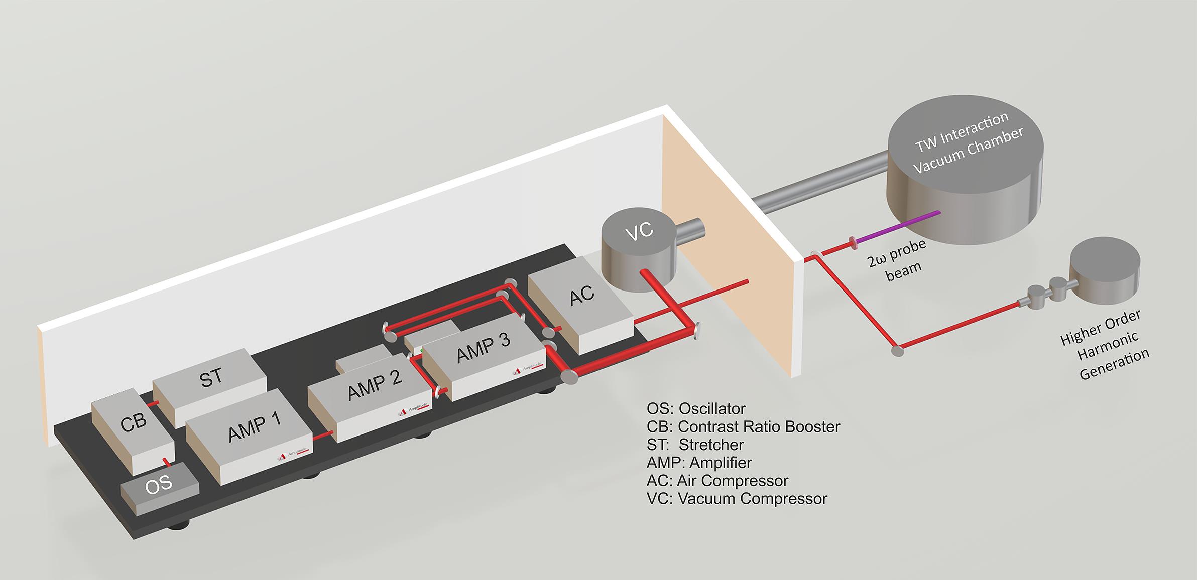
Figure 1.A 3D schematic layout of the ZEUS 45 TW laser system.
Two acousto-optic programmable modulators (AOPMs) are used to provide fine adjustment of both the phase and the amplitude of the laser pulse spectrum for the optimisation of the pulse output. An AOPM placed inside the RA cavity provides a wide flat spectrum at the output of the first amplifier. The wavelength of the spectrum is typically in the region of 800 ± 35 nm. Feedback from optical spectrometer measurements is fed to the programmable controller to adjust the spectrum’s amplitude. The other AOPM after the stretcher allows for further adjustment to flatten the phase over all the spectrum at the output of the compressor, by the single-shot phase diagnostic (Wizzler) providing feedback to the programmable controller. At the exit of the second amplifier, a beam splitter takes 5% of the main beam energy. This portion of the beam is used as an auxiliary interaction or as a diagnostic probe beam. The beam is compressed using dedicated gratings in air and provides pulses of 10 mJ in energy in a 25 fs duration pulse. The temporal contrast of the laser, as measured by a third-order autocorrelator (SEQUOIA) is typically as follows: 1 × 10⁻⁴ at 1 ps, 2 × 10⁻⁷ at 5 ps, 5 × 10⁻⁸ at 10 ps, 8 × 10⁻⁹ at 20 ps, 2 × 10⁻¹⁰ at 100 ps, and 1 × 10⁻⁹ at 400 ps. Figure 2 shows a measurement of ZEUS laser contrast just after the compressor. The energy variation of the system is typically less than 1% root mean square (RMS) in a 30 min period.
![]()
Figure 2.The contrast of the ZEUS laser system as measured by the SEQUOIA third-order autocorrelator.
The 55 mm diameter main laser beam is compressed using a double-pass grating system and is transported under vacuum to the 1.5 m diameter, 0.7 m height cylindrical target chamber that achieves pressures of 10–7 mbar. Separation of the vacuum between the target and the compressor chambers is achieved by a windowed gate valve. Typically, the gate valve is open when the target chamber pressure is less than 10–6 mbar, thus matching the pressure in the compressor chamber. This avoids unnecessary contamination of the compressor gratings. The target chamber shown in Figure 3 has eight ISO 200 ports distributed in the horizontal plane of the laser–target interaction and further four ISO 160 ports on the lid of the chamber.
![]()
Figure 3.A drawing of the ZEUS target interaction chamber for ion-acceleration experiments. Also shown is a typical image of the laser pulse focused with the
Access to the chamber is accomplished by complete removal of the lid of the chamber. The target chamber optics board is not mechanically isolated from the chamber but a pointing system inside the chamber allows the laser to be repointed under vacuum to compensate for the distortion of the pumped chamber. To accommodate the transport of the 55 mm diameter beam in the chamber, 4 inch (101.6 mm) in diameter gold and dielectric mirrors are available for steering the beam, and 3 inch (72.6 mm) in diameter parabolic mirrors are the choice for focusing the beam. The vacuum chamber offers a high degree of flexibility for experimental layouts and is currently configurable with two focusing off-axis parabola optics. One is an f/2, 15 cm focal length, 30° off-axis parabola which allows for the focusing of the beam to a 2.8 μm diameter focal spot. With this optic, a focused intensity exceeding 6 × 10²⁰ W/cm2 can be achieved. This high peak intensity exacerbates the problem of the inherent pre-pulse of the laser system and there is provision in the target chamber for the implementation of a double plasma mirror system[77]. The other focusing optic is an f/13, 100 cm focal length, 8° off-axis parabola, which for the laser’s beam parameters offers a 25 μm diameter focal spot with a Rayleigh length of the order of a millimetre. This configuration is suitable for experiments that require the laser to remain focused over enhanced distances such as for the electron acceleration using a wakefield scheme or for the production of coherent radiation sources from HHG[55] and betatron-type X-ray radiation[78]. There is the option to use either a regular low-density gas for this purpose or a high-density gas jet[79] for the generation of overdense plasmas for the production of energetic ions. Both focusing optics can accommodate the use of multi-shot solid-target configurations to negate the need to break vacuum between shots. To establish the baseline characteristics of the laser’s ability to generate secondary sources a campaign of experiments and simulations was executed to investigate the generation of protons from solid targets and electrons from the interaction of the laser with a gas jet in a non-optimized wakefield scheme. Experiments were also performed to ascertain the extent of the pre-plasma generated by the laser and its impact on the production of secondary particles and photons. A large extended pre-plasma at the front of the solid target is shown in Figure 4. It was observed up to 1 ns before the main pulse arrival at a transversely probed 30 μm aluminium target. The extent of the pre-plasma, which in this case has a scale length of the order of 30 μm, is more than sufficient to supress proton acceleration by defocusing the laser and reducing the accelerating fields at the solid vacuum interface. In addition, for thinner targets, plasma formation was observed to occur at the rear of the target prior to the arrival of the main pulse. The pre-plasma formation can be reduced by the operation of a double plasma mirror setup already installed in the experimental chamber or the use of a saturable absorber after the RA in the laser system. The use of a saturable absorber is advantageous over the plasma mirror since it can operate at high-repetition-rate laser mode. Experiments are ongoing for the suppression of the pre-plasma using both options.
![]()
Figure 4.A shadowgram captured 650 ps before the arrival of the main pulse. The laser is incident from the left to the right onto a 30 μm thick solid aluminium target.
3 Integrated ZEUS laser system experimental chamber commissioning
For the transition to a stage where the facility could be used as an access point for other national and international researchers, basic characterization of the focused laser parameters of the beam inside the experimental chamber had to be established. To achieve this goal, an experimental campaign was executed to exploit the two default experimental chamber configurations: one that uses a long 100 cm focal length parabola and the other a short 15 cm focal length parabola. Experiments to determine the capability of the laser system to accelerate electrons with a long focal length parabola, where a long Rayleigh length is required in a wakefield scheme, and to accelerate protons in a solid target, where a short focal length parabola is required to provide the maximum intensity, were designed and executed. The long focal length parabola has a 25 μm FWHM focal spot that provides a peak intensity in excess of 7 × 10¹⁸ W/cm2 on the target. The short focal length off-axis parabola creates a tight focus of the beam with a focal spot of 2.8 μm FWHM achieving an intensity of approximately 6 × 10²⁰ W/cm2 on target. These intensities are based on a nominal 1 J on target and a 25 fs pulse. In other experiments, the auxiliary probe beam of the laser was directed into an adjacent chamber with a static gas fill for HHG studies.
The experimental layout of the target chamber while using the short focal length parabola is shown in Figure 3. The inset in Figure 3 (bottom left) shows the typical focal spot of the laser pulse focused by the f/2 off-axis parabola. In this case, most of the energy was contained within the first maximum of the focal spot. A faint ring of light surrounding the focal spot contained only a few percent of the laser energy. The beam was propagated into the chamber where a gold-coated mirror guided the beam onto the 30° off-axis, 15 cm focal length parabola. This high degree of focusability was achieved without the need for adaptive optics and indicates a laser system delivering pulses with a flat phase front. The beam was incident at 45° onto the solid target surface so as to reduce damage onto the parabola coating. The probe beam, which passes parallel to the target surface, was synchronized with the main beam using a motorized delay stage enabling the ability to probe and characterize at different times the evolution of plasma from both the front and back of the target. To determine the exact time the main beam and the probe beam were incident at the target surface, a glass target was inserted at the target position, was rotated to reflect the main beam along the probe channel, and was positioned so that the main beam was focused onto it. The precise synchronization of the beams was achieved when an interference pattern was observed on the probe camera indicating that the main beam was hitting the glass surface while the probe beam was simultaneously passing through the glass. A focused shadowgraphy diagnostic was used to image the target and its plasma evolution on an 8-bit CCD camera. The probe beam itself was frequency doubled by a barium borate (BBO) crystal before it entered the vacuum chamber. A 400 nm bandpass filter blocked the infrared scattered light of the main beam and any self-emission from reaching the camera. A second CCD camera recorded the retro reflection of the focal spot on the target, through an imaging lens, to monitor the focus quality and thereby pre-align the target before the shot. A re-entrant tube is also available on the chamber which supports the placement of samples close to the secondary particles emitted from the rear of the solid target while allowing the sample to be maintained at atmospheric pressure.
4 Proton acceleration from solid targets experimental platform
For this experimental campaign, aluminium targets with thicknesses varying from 1.5 to 70 μm were used. The energy of the p-polarized laser beam (800 nm central wavelength) at the target area was in the region of 1 J and was focused to a spot of 2.8 μm FWHM in diameter. The pulse duration was adjusted to be 25, 80, and 150 fs. A stack of 20 pieces of radiochromic films (RCFs; Gafchromic HD-810 or EBT3 depending on the required sensitivity) was used in the first instance to measure the proton emission at the rear of the solid target. RCF detectors were calibrated using a typical 60Co radiation source. The stack of RCF which can measure different types of ionizing radiation emitted from the rear of the target was placed at a distance of 2 cm along the rear target normal. The stack was covered with 13 μm thick aluminium foil to protect the RCF stack from laser irradiation and damage from plasma ejected from the rear surface of the target. Given the thickness of the stack, it was anticipated that this diagnostic was useful for measuring protons up to an energy in the region of 15 MeV. Figure 5 shows the scanned pieces of RCF when the laser irradiated with eight consecutive shots the 10 μm Al thick target. Signal can be clearly seen up to the last piece of RCF and it is likely this signal would have continued to a measurable extent beyond this layer. This signal is from electrons because protons with energy higher than 2.5 MeV are needed to penetrate through the 110 μm thick RCF used. Such energy protons are not produced in these experiments as described in the following. Furthermore, in other similar shots, where a CR39 nuclear track detector was positioned immediately after the first layer of RCF, no proton signal was recorded so the signal recorded on the RCF is attributed to sub-MeV electrons. Although this setup is developed for proton acceleration, for the completion of the discussion here, we present typical results of the electron dose observed in these experiments in the following.
![]()
Figure 5.The scanned irradiated radiochromic films (RCFs), accompanied by the calibrated (bottom) RCFs indicating a falloff in optical density and therefore dose as the electron energy increases. The energies indicated are a guide to the minimum electron energy required to penetrate through to a particular layer. The accumulated dose corresponds to eight laser shots.
Assuming the signal is solely due to electrons and not X-rays, a valid assumption given the poor bremsstrahlung conversion efficiency, a spectrum of the electron fluence on the central region of the RCF stack can be deconvolved[80]. Over the useable range of the diagnostic, in this case up to 1 MeV, the spectrum falls off over a factor of 10 as shown in Figure 6. This is the spectrum along the rear target normal. In this region, assuming an exponential distribution of the form dN/dE ∼ exp(–E/T), where dN/dE is the number of electrons per unit energy interval and T is the characteristic temperature, or the inverse of the gradient in log space, the spectrum can be characterized with an electron temperature of approximately 300 keV. However, this diagnostic does not characterize the higher-energy electrons present which extend well beyond 1 MeV. It is likely that the spectrum of electrons recorded at the rear of the solid target is enhanced by the substantial pre-pulse of the laser pre-exploding the target.
![]()
Figure 6.Electron spectrum as recorded in the central region of the radiochromic film.
As mentioned, a re-entrant tube was attached to the chamber that terminated at a distance of 4 cm from the rear of the solid target. This allowed the possibility for placing biological samples close to the secondary radiation source while keeping them at atmospheric pressure. A typical electron dose profile under atmospheric pressure, accumulating the dose of 20 shots on an RCF placed inside the re-entrant tube, is shown in Figure 7. The result shows an excellent dose profile of electrons of high repeatability and stability. The dose recorded on the RCF is apertured by a ring that holds a 150 μm plastic window that forms the barrier between atmospheric pressure and the vacuum inside the chamber.
![]()
Figure 7.Electron dose profile and iso-dose lines of the radiochromic films (EBT3) irradiated by 20 shots inside the re-entrant tube (left). On the right, a line out of the dose as a function of distance is shown.
To measure the proton energy and to ascertain whether it was possible that MeV protons had been accelerated and passed at least the 13 μm thick aluminium protective layer on the RCF placed inside the chamber behind the solid target, a multilayer aluminium mask was attached to the front surface of a single piece of CR39. The mask was divided into 8 sectors, each of them having increasing layers of 13 μm thick aluminium foil, resulting thus in a single piece of CR39 filtered with aluminium ranging in thicknesses from 13 to 108 μm. Each consecutive sector filters protons of increasingly higher energy. Protons with enough energy to just pass through a particular thickness which coincides with the Bragg peak, damage the surface of the CR39. By etching the CR39 in 6 mol/L NaOH solution for 6 hours, the maximum proton energy can be determined by inspecting the pits etched on the CR39 surface. Figure 8 presents a typical sample of data recorded with the filtered CR39. Protons in excess of 1 MeV for all combinations of target thicknesses and pulse durations were measured by this diagnostic. Figure 8(a) presents data of a 70 μm thick aluminium target irradiated by 25 fs pulses at 1020 W/cm2 intensity on target. Protons in two sectors of the CR39 were observed (Figure 8(a)), corresponding to maximum proton energies in the range of 1.5–1.9 MeV. Figure 8(b) shows data for a 30 μm thick aluminium target irradiated by 80 fs pulses under the same focusing conditions as in Figure 8(a). Protons in three sectors corresponding to maximum proton energies in the range of 1.5–2.3 MeV were detected. When the laser pulse duration was increased to 150 fs, a maximum energy of 1.9 MeV was observed for a 30 μm thick aluminium target, as shown in Figure 8(c). In these experiments, the optimal target thickness was in the region of some tens of micrometres producing a maximum proton energy up to 2.3 MeV.
![]()
Figure 8.A series of scanned images of a filtered CR39. (a) Protons produced by the irradiation of 70 μm thick Al target with the 25 fs laser pulse. (b) Protons produced by the irradiation of 30 μm thick Al target with the 80 fs laser pulse. (c) Protons produced by the irradiation of 30 μm thick Al target with the 150 fs laser pulse. (d) Schematic representation indicating the thickness of the Al foil filtering on each sector of the diagnostic. The maximum proton energy producing and generating a crater on the surface of the CR39 nuclear track detector is in the range of 1.5–2.3 MeV which corresponds to image (b). Higher proton energies if they existed would have appeared on the 52 μm and the other Al filtered sectors which lack signal for all cases examined.
It was expected that thin targets would favour a higher proton energy in these experiments given the short pulse of the laser, but the inherent pre-pulse of the laser forms a large pre-plasma on the front and in some cases the rear of the target that inhibits proton acceleration. In general, a clean solid–vacuum interface enhances proton acceleration at both the front and rear of a solid target. In these experiments it is likely that targets a few micrometres thick were effectively destroyed by the pre-pulse of the laser. Therefore, it was observed that targets of the order of 30 μm thick were the only ones capable of producing any recordable proton signal. The density of protons recorded on the CR39 indicated in Figure 8 was sufficiently unsaturated so that a spectrum could be reduced from counting the observed pits. The spectrum is shown later in Figure 18 where the measured proton spectrum is compared with particle-in-cell (PIC) simulations. However, it must be noted that this spectrum represents the tail end of the spectrum that was measured and not the bulk of the protons that were accelerated.
5 Electron acceleration from gas jet targets experimental platform
For this part of the experimental campaign, the 100 cm focal length f/13 parabola was configured to point along a major axis of the chamber as shown in Figure 9.
![]()
Figure 9.A drawing of the ZEUS target interaction chamber configured for a long focal length parabola for electron acceleration in a laser wakefield scheme.
An electromagnetic gas solenoid valve coupled either to a 3 mm diameter plastic conical nozzle or to a 0.8 mm metallic cylindrical nozzle was positioned at the laser pulse focus. This gas jet target typically produces an atomic density of approximately 5 × 1018 cm–3 with a typical backing pressure between 35 and 45 bar of helium gas for the conical nozzle making it suitable for electron acceleration in a wakefield scheme. For the cylindrical nozzle the typical operating backing pressure was at 12 bar producing narrower atomic density profiles of maximum atomic density 1 × 1019 cm–3. Other gases such as nitrogen, neon, or argon were also used for multi-parametric studies[52]. The density profile of the gas jet was not absolutely uniform, but was sufficiently within the optimized electron density for accelerating electrons to high energy. In these experiments, the laser focal spot of the 25 fs laser pulse achieved by the f/13 parabolic mirror was measured to be 25 μm at FWHM providing a peak intensity of approximately 7 × 10¹⁸ W/cm2. To characterize the interaction region of the laser with the gas jet, the optical probe beam was passed perpendicularly to the interaction region and the shadowgram was recorded on an optical CCD camera outside the target chamber. To characterize the accelerated electrons, a magnetic spectrometer, consisting of two parallel opposed 0.4 T magnets deflecting the electron onto a Lanex scintillation screen, was used. The magnetic field was mapped with a Hall probe and the electron dispersion onto the Lanex detector plane was determined by numerical calculation. The screen was imaged with an optical CCD camera and the diagnostic was calibrated[81] to ascertain the energy and absolute number of electrons that were accelerated.
The position of the focused laser relative to the gas jet, together with the helium gas jet backing pressure was adjusted until consistency in the pointing of the electron beam and the energy was achieved. As in the case of other wakefield acceleration experiments, a highly collimated quasi-monoenergetic beam of electrons was produced. Two typical raw images from the Lanex screen are shown in Figure 10. The top image is recorded using the cylindrical nozzle at a backing pressure of 12 bar of He gas whereas the bottom is taken using the conical nozzle at a backing pressure of 40 bar also of He gas. Typical quasi-monoenergetic spectrum using the cylindrical nozzle is indicated in Figure 11. The divergence was typically of the order of few millirad and the total charge of the order of 1 nC. The maximum electron energy but of broader spectrum achieved in these experiments was in excess of 200 MeV as shown in the bottom image of Figure 10 with the use of the conical nozzle.
![]()
Figure 10.Relativistic electron spectral images as recorded by a CCD camera that is imaging the Lanex screen.
![]()
Figure 11.Typical quasi-monοenergetic electron spectra produced in the laser wakefield interaction and at the corresponding total charge.
The laser was operated at a maximum repetition rate of 0.1 Hz when a gas jet target was used, in order to keep a high vacuum in the compressor vacuum chamber. A plan to mitigate the large pressure excursion when the gas jet is operated will require differential pumping or the future use of a gas cell. The stability of the electron beam was found to be very good. In around 3000 consequent shots, only minor shot-to-shot fluctuations of the energy and pointing of the beam were observed. The placement of a Schott RG850 saturable absorber after the RA in the laser system was observed to reduce pre-plasma formation in the gas jet target and enhance the reproducibility and stability of the observed electron beam, an effect which is under further investigation.
6 A betatron-type X-ray source platform
An experimental setup offering the capabilities for performing detailed studies related to the generation of betatron-type X-rays and their use in sub-micrometre imaging applications has been developed. Such secondary X-ray sources have a spatial coherence of the order of a few micrometres (point-like source), thus fulfilling the requirements for a coherent X-ray source appropriate for imaging applications in the micro-scale. The setup is illustrated in Figure 12. The laser beam was focused onto a pulsed gas jet target by the 100 cm focal length f/13 off-axis parabolic mirror, resulting in a laser peak intensity in the range of 1018–1019 W/cm2. In these conditions the gas target is highly ionized during the leading edge of the laser pulse. The ponderomotive force of the laser expels electrons away from the focal spot creating an electron cavitated region, the so-called bubble, as illustrated in the inset of Figure 12. Electrons can enter the plasma bubble according to various mechanisms (self-injection, direct ionization injection, etc.) where they can be trapped in a forward accelerating region of electric field while performing betatron-type oscillations[82]. Electrons are accelerated to relativistic energies while betatron-type X-rays are generated. The setup allowed for the simultaneous recording of both the relativistic electrons and the emitted X-rays. This experimental layout allowed for a more comprehensive study of the generated X-rays and how they were related to the corresponding relativistic electrons. The experimental setup was equipped with a femtosecond laser shadowgraphy diagnostic (not shown in Figure 12) for monitoring the plasma channel formation, necessary for the effective electron acceleration and betatron-type X-ray generation. A Nomarski-type interferometer (also not shown in Figure 12) was used for determining the gas density profiles, necessary for the electron density determination.
![]()
Figure 12.The betatron-type X-ray source setup. (1) Off-axis parabolic mirror with 1 m focal length (
These studies focused on the identification of the betatron-type X-rays and their correlation with the observed directional relativistic quasi-monoenergetic electrons from the interaction of high-power laser pulses with helium gas targets as reported in Ref. [83]. Having achieved this decisive initial step, attention was focused on the role of the multi-electron gas targets in the LWFA mechanism and the production efficiency of the corresponding betatron-type X-ray radiation. In a recent publication[52] we investigated the role of the multi-electron targets (He, N2, Ne, and Ar) in the bubble formation dynamics and ionization injection features, mapped in the generated X-rays and electron spectra. We showed in a proof-of-principle study that by using a multi-electron gas target and appropriately adjusting the pumping laser intensity, the efficiency of the betatron-type X-rays can be improved. Figure 13 shows a typical relativistic electron spectral image along with the corresponding betatron-type X-ray image as well as a shadowgram of the plasma channel, all recorded simultaneously in a single laser shot. Typical total electron charge of a few nanocoulombs per laser shot has been determined experimentally in the bubble LWFA acceleration regime. According to the study presented in Ref. [52], X-ray photon numbers as high as 109 per laser shot have been demonstrated with a typical beam divergence in the range of 12–16 mrad. Currently, our studies are oriented towards the improvement of the efficiency and control of the betatron-type radiation characteristics via experimental parameters such as the laser pulse structure, the gas target types, and the pulsed-jet nozzle geometries. In the near future, the experimental platform will be equipped with an extra vacuum chamber that will host an X-ray spectrometer for an on-line determination of the X-ray spectrum, the current X-ray CCD camera, and a sample holder for sample imaging in sub-micrometre scale.
7 HHG secondary source platform
An experimental platform which delivers coherent XUV radiation within the bandwidth of λ = 22–124 nm has recently been developed. The complementary low energy laser beam of the ZEUS laser system was focused using a 38 cm focal length, 5 cm diameter optical plano-convex BK7 lens close to the exit of a semi-infinite static gas cell reaching peak intensities of the order 1014–1015 W/cm2. At these intensities, the outer electrons of the atoms undergo tunnel ionization[84], and under the force of the alternating strong laser electric field can follow closed trajectories that direct them to recollide with the parent ion and, thus, emit XUV radiation[55,56]. Upon a macroscopic coherent addition of the generated XUV radiation, based on quasi-phase-matching conditions[61,69,85–87], a secondary coherent XUV beam is formed, which propagates along with the laser beam, as shown in Figure 14. The laser beam was filtered by two Si wafers, placed at the Brewster angle for the laser beam, resulting in an XUV beam, which was spectrally analysed by a grazing-incidence flat-field diffraction grating (Hitachi 001-0639). The whole HHG XUV spectra were recorded in scanning mode with the use of the movable micro-channel plate (MCP) detector (not shown in Figure 15), while a portion of the spectrum, covering five harmonics in the bandwidth of 35–58 nm, was recorded in shot-to-shot mode with the XUV CCD camera (Raptor Photonics, Eagle XO).
![]()
Figure 13.Typical relativistic electron spectral image (top), corresponding betatron-type X-ray image (middle), and corresponding shadowgram of the plasma channel (bottom) all recorded simultaneously from the interaction of the main laser pulse with the gas jet.
![]()
Figure 14.The secondary coherent XUV source setup based on HHG. The red colour beam corresponds to the IR laser beam whereas the blue colour beam corresponds to the generated at the gas cell HHG XUV radiation, which is subsequently spectrally analysed by the diffraction grating and detected by the XUV CCD camera.
![]()
Figure 15.Typical XUV spectra generated in 80 mbar argon gas by 1 mJ laser pulses. They were obtained in scanning mode with the movable MCP detector and in shot-to-shot mode obtained with the XUV CCD camera shown in the inset.
The setup consisted of three connected vacuum chambers. The first chamber was a semi-infinite static cell that hosts the gas in pressures ranging typically from 25 to 130 mbar. The second chamber in line was a differentially pumped chamber, which was necessary for separating the first high-pressure chamber from the third low-pressure chamber, where the filtering and detection of the harmonics are completed. The detection chamber is operated at a pressure in the region of 10–6 mbar.
Figure 15 presents typical HHG XUV spectra generated in 80 mbar argon gas by 1 mJ ZEUS laser pulses, reaching peak intensities of 1.0 × 10¹⁴ W/cm2. The secondary XUV source was studied systematically by investigating the HHG production quality and characteristics by varying (i) the laser beam intensity, (ii) the laser beam aperture size, (iii) the location of the focal area with respect to the exit of the semi-infinite cell, (iv) the laser pulse temporal characteristics, (v) the generating gas type including mixes of gases, and (vi) the generating gas pressure. Certain favourable conditions were identified for generating high-quality HHG XUV secondary beams that will be detailed in a forthcoming publication.
This secondary HHG XUV source is being developed in the framework of the research program entitled ‘Development of a coherent X-ray multispectral microscopy system’ supported by the action ‘Research–Create–Innovate’[88]. The final goal of this research action is to develop a system for multi-spectral microscopy in the region of ‘soft’ X-rays. The presented setup will be further developed to include, in addition to the current spectral measurement option, a multi-spectral filtering device, based on specific reflective optical components, that will select the necessary XUV wavelength. The selected wavelength beam will be guided to a fourth chamber, attached in line to the third, for performing coherent diffraction imaging (CDI) measurements[89,90]. The fourth chamber will be equipped with a controllable target holder and second XUV CCD camera for recording the CDI images. The final system will be of very high added value and extremely useful for the fast imaging with coherent light of surface micro-structures[89,90], which until today is impossible to achieve using the existing conventional laser sources.
8 Pulsed power plasma devices platforms
It is not within the scope of this article to extend on the pulsed power plasma generators developed at IPPL, however, they are mentioned here for completion purposes to inform the community about their existence and their possible use for dense plasma diagnostics. The devices are loaded as Z-pinch, X-pinch, multi-wire or plasma focus configurations. The X-pinch, for example, is an excellent diagnostic device for high-spatial-resolution point X-ray backlighting plasma radiography including laser-generated plasmas. In addition to their use for the generation of XUV radiation for dense plasma diagnosis, they are excellent devices for basic plasma physics studies such as the growth of plasma instabilities. The technical parameters and specifications of these devices can be found in Refs. [91–95]. Upon request the devices can be offered to users either as hard X/XUV radiography diagnostics synchronized to the ZEUS laser or as individual plasma sources for experiments.
9 Simulations platform
To support the needs of designating the experimental campaigns at IPPL as well as to contribute to the better understanding of the experimental results, computational studies have been developed for advanced numerical models and simulation schemes. The simulations follow the experimental specifications described in the previous sections based on the laser systems operating at IPPL. The experiments for proton and electron acceleration were initially simulated in 2D and they were extended where necessary to 3D models to simulate the experiments more accurately. The demanding simulations are performed on the high-performance computer for Advanced Research Information System (ARIS) of the Hellenic National Infrastructure for research and technology[96]. A series of 2D and 3D simulations have been performed up to date. The codes EPOCH[97] and PIConGPU[98] are used for the PIC simulations. In a recent publication[99], we investigated case studies of proton and electron acceleration experiments which follow the laser specification of the 45 TW ZEUS laser system at IPPL and the Extreme Light Infrastructure (ELI-Romania) on the scalability and the performance of PIC simulations on CPU and GPU architectures. Figure 16 shows results on proton charge densities generated by the simulation after the interaction of a 25 fs laser pulse with a 50 nm hydrogen contamination layer on 13 μm thick Al target. In Figure 16(a) the target is free of pre-plasma whereas in Figure 16(b) a pre-plasma exists with a scale length of 3.5 and 0.35 μm at the front and rear of the target, respectively. The aim of the simulation was to predict the effect of the pre-plasma generated by the pre-pulse of the ZEUS laser on the TNSA mechanism for proton acceleration.
![]()
Figure 16.Proton charge density at 250 fs of the simulation for (a) the high-contrast, free of pre-plasma case and (b) the case where intense pre-pulses generate pre-plasmas before the main pulse arrives.
Both images show that protons are accelerated in the critical surface at the front of the target. In the case where there is no pre-plasma at the front and rear of the target, the front side accelerated protons have higher momentum. The phase space of the protons, at 250 fs of the interaction, is shown in Figure 17 where accelerated protons from the front and rear surfaces are exposed. At the front of the target the critical plasma density surface is pushed forward by the radiation pressure and in association with the hole boring establishes the front surface acceleration spectrum of the protons by the co-existence of the ambipolar fields and the shock acceleration mechanisms[39,100–102]. At the rear of the target, the strong charge separation of the TNSA, accelerates the protons. In addition, protons are accelerated in the opposite direction by plasma expansion.
![]()
Figure 17.Proton phase space at 250 fs of the simulation for (a) the high-contrast, free of pre-plasma case and (b) the case where intense pre-pulses generate pre-plasmas before the main pulse arrives.
The maximum proton energy is close to 8 MeV for the case that there is no plasma expansion due to the laser pre-pulse. Results for the case where there is plasma formation at the front and the rear of the target caused by the pre-pulse of the laser reduce the maximum energy down to 3.8 MeV. The pre-plasma formed at the front and rear of the target reduces the effectiveness of the proton acceleration at both the front and rear of the target where a sharp density profile is favourable for proton acceleration[103,104].
Figure 18 presents the proton spectrum as a function of the proton kinetic energy in MeV. Plotted here are the spectra for the cases where there is (red line) and there is
![]()
Figure 18.Proton spectrum as a function of the energy for the case where there is no pre-plasma (blue line) at the front and rear of the target and for the case where there is pre-plasma (red line) at the front with 3.5 μm scale length and at the rear with 0.35 μm scale length.
no (blue line) pre-plasma at the front and rear of the target. Although the pre-plasma scale length used in the simulations was shorter than that measured experimentally, in order to relax the high computational demands, the results prove the damaging role of the pre-plasma effect. Experiments and simulations suggest that the mitigation of the pre-plasma is a necessity for the proton energy to be increased in the range from 5 to 10 MeV and fully take advantage of the ZEUS laser very good overall shot-to-shot stability.
10 Conclusions
The ZEUS 45 TW laser system is capable of accelerating electrons to a maximum energy of 200 MeV in a laser wakefield configuration and has the potential to accelerate protons up to 10 MeV with the elimination of the pre-plasma using a double plasma mirror system or a saturable absorber in the laser system. Currently, the laser pre-pulse and the subsequent pre-plasma on solid targets limit the maximum proton energy observed to just over 2 MeV. The ZEUS laser is also capable of generating coherent XUV sources such as betatron-type X-rays and HHG. The ZEUS laser system offers a flexible target interaction chamber that can be configured for both long and short focal length focusing systems for solid and gas target interactions. The laser and the facility at IPPL form part of national infrastructure that offers external users the opportunity to use laser-generated secondary sources with a pool of diagnostics tools including the use of pulsed power plasma devices. To complement the laser, high-energy particle detectors have been developed to allow the characterisation of the sources and are available as a diagnostic suite for external users. The 10 Hz laser system is currently limited to 0.1 Hz for use with gas jet targets in the main interaction chamber and it is limited to single-shot operation for solid targets. The auxiliary probe beam, that has been used for HHG in a separate static gas fill chamber, allows for coherent XUV production at 10 Hz.
References
[1] G. Mourou. Rev. Mod. Phys., 91, 030501(2019).
[2] D. Strickland, G. Mourou. Opt. Commun., 85, 219(1985).
[3] J. W. Yoon, Y. G. Kim, I. W. Choi, J. H. Sung, H. W. Lee, S. K. Lee, C. H. Nam. Optica, 8, 630(2021).
[4] P. Zhang, S. S. Bulanov, D. Seipt, A. V. Arefiev, A. G. R. Thomas. Phys. Plasmas, 27, 050601(2020).
[5] F. Albert, M. E. Couprie, A. Debus, M. C. Downer, J. Faure, A. Flacco, L. A. Gizzi, T. Grismayer, A. Huebl, C. Joshi, M. Labat, W. P. Leemans, A. R. Maier, S. P. D. Mangles, P. Mason, F. Mathieu, P. Muggli, M. Nishiuchi, J. Osterhoff, P. P. Rajeev, U. Schramm, J. Schreiber, A. G. R. Thomas, J. Vay, M. Vranic, K. Zeil. New J. Phys., 23, 031101(2021).
[6] C. N. Danson, C. Haefner, J. Bromage, T. Butcher, J. F. Chanteloup, E. A. Chowdhury, A. Galvanauskas, L. A. Gizzi, J. Hein, D. I. Hillier, N. W. Hopps, Y. Kato, E. A. Khazanov, R. Kodama, G. Korn, R. Li, Y. Li, J. Limpert, J. Ma, C. H. Nam, D. Neely, D. Papadopoulos, R. R. Penman, L. Qian, J. J. Rocca, A. A. Shaykin, C. W. Siders, C. Spindloe, S. Szatmári, R. M. G. M. Trines, J. Zhu, P. Zhu, J. D. Zuegel. High Power Laser Sci. Eng., 7, e54(2019).
[7] M. Tabak, J. Hammer, M. E. Glinsky, W. L. Kruer, S. C. Wilks, J. Woodworth, E. M. Campbell, M. D. Perry. Phys. Plasmas, 1, 1626(1994).
[8] M. Tatarakis, J. R. Davies, P. Lee, P. A. Norreys, N. G. Kassapakis, F. N. Beg, A. R. Bell, M. G. Haines, A. E. Dangor. Phys. Rev. Lett., 81, 999(1998).
[9] E. L. Clark, K. Krushelnick, J. R. Davies, M. Zepf, M. Tatarakis, F. N. Beg, A. Machacek, P. A. Norreys, M. I. K. Santala, I. Watts, A. E. Dangor. Phys. Rev. Lett., 84, 670(2000).
[10] E. Esarey, C. B. Schroeder, W. P. Leemans. Rev. Mod. Phys., 81, 1229(2009).
[11] C. G. R. Geddes, C. Toth, J. van Tilborg, E. Esarey, C. B. Schroeder, D. Bruhwiler, C. Nieter, J. Cary, W. P. Leemans. Nature, 431, 538(2004).
[12] J. Faure, Y. Glinec, A. Pukhov, S. Kiselev, S. Gordienko, E. Lefebvre, J.-P. Rousseau, F. Burgy, V. Malka. Nature, 431, 541(2004).
[13] S. P. D. Mangles, G. Genoud, M. S. Bloom, M. Burza, Z. Najmudin, A. Persson, K. Svensson, A. G. R. Thomas, C.-G. Wahlstrom. Phys. Rev. ST Accel. Beams, 15, 011302(2012).
[14] M. Tatarakis, F. Beg, E. Clark, A. Dangor, R. Edwards, R. Evans, T. Goldsack, K. Ledingham, P. Norreys, M. Sinclair. Phys. Rev. Lett., 90, 175001(2003).
[15] A. Lapucci, A. Pirri, D. Giulietti, F. Rossi, G. Gatti, G. Grittani, G. Toci, J. Hostaša, L. Esposito, L. Labate, L. A. Gizzi, M. Ciofini, M. Kando, M. Krus, M. Vannini, M. P. Anania, P. Ferrara, T. Levato, Y. Oishi, L. A. Gizzi, L. A. Gizzi, M. P. Anania, M. Ciofini, L. Esposito, P. Ferrara, G. Gatti, D. Giulietti. Proceedings of Conference on Lasers and Electro-Optics Pacific Rim (CLEO-PR)(2013).
[16] K. F. Kakolee, D. Doria, M. Borghesi. Proceedings of Conference on Lasers and Electro-Optics Pacific Rim (CLEO-PR)(2015).
[17] C. Spielmann. Frontiers in Optics 2015(2015).
[18] S. Kneip, C. McGuffey, J. L. Martins, S. F. Martins, C. Bellei, V. Chvykov, F. Dollar, R. Fonseca, C. Huntington, G. Kalintchenko, A. Maksimchuk, S. P. D. Mangles, T. Matsuoka, S. R. Nagel, C. A. J. Palmer, J. Schreiber, K. T. Phuoc, A. G. R. Thomas, V. Yanovsky, L. O. Silva, K. Krushelnick, Z. Najmudin. Nat. Phys., 7, 737(2011).
[20] https://eli-laser.eu. https://eli-laser.eu
[21] . Opportunities in Intense Ultrafast Lasers: Reaching for the Brightest Light(2018).
[22] W. P. Levin, H. Kooy, J. S. Loeffler, T. F. DeLaney. Br. J. Cancer, 93, 849(2005).
[23] M. Murakami, Y. Hishikawa, S. Miyajima, Y. Okazaki, K. L. Sutherland, M. Abe, S. V. Bulanov, H. Daido, T. Z. Esirkepov, J. Koga, M. Yamagiwa, T. Tajima. AIP Conf. Proc., 1024, 275(2008).
[24] U. Masood, M. Bussmann, T. E. Cowan, W. Enghardt, L. Karsch, F. Kroll, U. Schramm, J. Pawelke. Appl. Phys. B., 117, 41(2014).
[25] H. Daido, M. Nishiuchi, A. S. Pirozhkov. Rep. Prog. Phys., 75, 056401(2012).
[26] L. Labate, D. Palla, D. Panetta, F. Avella, F. Baffigi, F. Brandi, F. D. Martino, L. Fulgentini, A. Giulietti, P. Köster, D. Terzani, P. Tomassini, C. Traino, L. A. Gizzi. Sci. Rep., 10, 17307(2020).
[27] M. Borghesi, S. Kar, R. Prasad, F. K. Kakolee, K. Quinn, H. Ahmed, G. Sarri, B. Ramakrishna, B. Qiao, M. Geissler, S. Ter-Avetisyan, M. Zepf, G. Schettino, B. Stevens, M. Tolley, J. Green, P. F. Foster, C. Spindloe, P. Gallegos, A. L. Robinson, D. Neely, D. C. Carroll, O. Tresca, X. Yuan, M. Quinn, P. McKenna, N. Dover, C. Palmer, J. Schreiber, Z. Najmudin, I. Sari, M. Kraft, M. Merchant, J. C. Jeynes, K. Kirkby, F. Fiorini, D. Kirby, S. Green. Proc. SPIE, 8079(2011).
[28] F. Hanton, D. Doria, K. F. Kakolee, S. Kar, S. K. Litt, F. Fiorini, H. Ahmed, S. Green, J. C. G. Jeynes, J. Kavanagh, D. Kirby, K. J. Kirkby, C. L. Lewis, M. J. Merchant, G. Nersisyan, R. Prasad, K. Prise, G. Schettino, M. Zpef, M. Borghesi. Proc. SPIE, 8779(2013).
[29] S. Raschke, S. Spickermann, T. Toncian, M. Swantusch, J. Boeker, U. Giesen, G. Iliakis, O. Willi, F. Boege. Sci. Rep., 6, 32441(2016).
[30] S. Gitomer, R. D. Jones, F. Begay, A. W. Ehler, J. F. Kephart, R. Kristal. Phys. Fluids, 29, 2679(1986).
[31] E. L. Clark, K. Krushelnick, M. Zepf, F. N. Beg, M. Tatarakis, A. Machacek, M. I. K. Santala, I. Watts, P. A. Norreys, A. E. Dangor. Phys. Rev. Lett., 85, 1654(2000).
[32] J. Badziak. J. Phys. Conf. Ser., 959, 012001(2018).
[33] S. P. Hatchett, C. G. Brown, T. E. Cowan, E. A. Henry, J. S. Johnson, M. H. Key, J. A. Koch, A. B. Langdon, B. F. Lasinski, R. W. Lee, A. J. Mackinnon, D. M. Pennington, M. D. Perry, T. W. Phillips, M. Roth, T. C. Sangster, M. S. Singh, R. A. Snavely, M. A. Stoyer, S. C. Wilks, K. Yasuike. Phys. Plasmas, 7, 2076(2000).
[34] A. Macchi, M. Borghesi, M. Passoni. Rev. Mod. Phys., 85, 751(2013).
[35] S. C. Wilks, A. B. Langdon, T. E. Cowan, M. Roth, M. Singh, S. Hatchett, M. H. Key, D. Pennington, A. MacKinnon, R. A. Snavely. Phys. Plasmas, 8, 542(2001).
[36] J. Badziak, G. Mishra, N. K. Gupta, A. R. Holkundkar. Phys. Plasmas, 18, 053108(2011).
[37] M. Grech, S. Skupin, A. Diaw, T. Schlegel, V. T. Tikhonchuk. New J. Phys., 13, 123003(2011).
[38] J. C. Fernández, B. J. Albright, F. N. Beg, M. E. Foord, B. M. Hegelich, J. J. Honrubia, M. Roth, R. B. Stephens, L. Yin. Nucl. Fusion, 54, 054006(2014).
[39] L. O. Silva, M. Marti, J. R. Davies, R. A. Fonseca, C. Ren, F. S. Tsung, W. B. Mori. Phys. Rev. Lett., 92, 015002(2004).
[40] J. Denavit. Phys. Rev. Lett., 69, 3052(1992).
[41] D. Jung, L. Yin, B. J. Albright, D. C. Gautier, R. Hörlein, D. Kiefer, A. Henig, R. Johnson, S. Letzring, S. Palaniyappan, R. Shah, T. Shimada, X. Q. Yan, K. J. Bowers, T. Tajima, J. C. Fernández, D. Habs, B. M. Hegelich. Phys. Rev. Lett., 107, 115002(2011).
[42] L. Yin, B. J. Albright, D. Jung, R. C. Shah, S. Palaniyappan, K. J. Bowers, A. Henig, J. C. Fernandez, B. M. Hegelich. Phys. Plasmas, 18, 063103(2011).
[43] T. Esirkepov, R. Bingham, S. Bulanov, T. Honda, K. Nishihara, F. Pegoraro. Laser Part. Beams, 18, 503(2000).
[44] V. Y. Bychenkov, V. F. Kovalev. Plasma Phys. Rep., 31, 178(2005).
[45] K. Krushelnick, E. L. Clark, Z. Najmudin, M. Salvati, M. I. K. Santala, M. Tatarakis, A. E. Dangor, V. Malka, D. Neely, R. Allott, C. Danson. Phys. Rev. Lett., 83, 737(1999).
[46] J. R. Castro, D. H. Char, P. L. Petti, I. K. Daftari, J. M. Quivey, R. P. Singh, E. A. Blakely, T. L. Phillips. Int. J. Radiat. Oncol. Biol. Phys., 39, 989(1997).
[47] A. Pukhov, J. Meyer-ter-Vehn. Appl. Phys. B, 74, 355(2002).
[48] I. Kostyukov, E. Nerush, A. Pukhov, V. Seredov. New J. Phys., 12, 045009(2010).
[49] V. Malka, S. Fritzler, E. Lefebvre, M. M. Aleonard, F. Burgy, J. P. Chambaret, J. F. Chemin, K. Krushelnick, G. Malka, S. P. Mangles, Z. Najmudin, M. Pittman, J. P. Rousseau, J. N. Scheurer, B. Walton, A. E. Dangor. Science, 298, 1596(2002).
[50] S. P. D. Mangles, C. D. Murphy, Z. Najmudin, A. G. Thomas, J. L. Collier, A. E. Dangor, E. J. Divall, P. S. Foster, J. G. Gallacher, C. J. Hooker, D. A. Jaroszynski, A. J. Langley, W. B. Mori, P. A. Norreys, F. S. Tsung, R. Viskup, B. R. Walton, K. Krushelnick. Nature, 431, 535(2004).
[51] W. Leemans, A. Gonsalves, H. Mao, K. Nakamura, C. Benedetti, C. Schroeder, C. Tóth, J. Daniels, D. Mittelberger, S. Bulanov, J. Vay, C. Geddes, E. Esarey. Phys. Rev. Lett., 113, 245002(2014).
[52] A. Grigoriadis, G. Andrianaki, M. Tatarakis, E. P. Benis, N. A. Papadogiannis. Appl. Phys. Lett., 118, 131110(2021).
[53] J. C. Wood, D. J. Chapman, K. Poder, N. C. Lopes, M. E. Rutherford, T. G. White, F. Albert, K. T. Behm, N. Booth, J. S. J. Bryant, P. S. Foster, S. Glenzer, E. Hill, K. Krushelnick, Z. Najmudin, B. B. Pollock, S. Rose, W. Schumaker, R. H. H. Scott, M. Sherlock, A. G. R. Thomas, Z. Zhao, D. E. Eakins, S. P. D. Mangles. Sci. Rep., 8, 11010(2018).
[54] A. E. Hussein, N. Senabulya, Y. Ma, M. J. V. Streeter, B. Kettle, S. J. D. Dann, F. Albert, N. Bourgeois, S. Cipiccia, J. M. Cole, O. Finlay, E. Gerstmayr, I. G. González, A. Higginbotham, D. A. Jaroszynski, K. Falk, K. Krushelnick, N. Lemos, N. C. Lopes, C. Lumsdon, O. Lundh, S. P. D. Mangles, Z. Najmudin, P. P. Rajeev, C. M. Schlepütz, M. Shahzad, M. Smid, R. Spesyvtsev, D. R. Symes, G. Vieux, L. Willingale, J. C. Wood, A. J. Shahani, A. G. R. Thomas. Sci. Rep., 9, 3249(2019).
[55] M. Lewenstein, P. Balcou, M. Y. Ivanov, A. L’Huillier, P. B. Corkum. Phys. Rev. A, 49, 2117(1994).
[56] P. B. Corkum. Phys. Rev. Lett., 71, 1994(1993).
[57] K. J. Schafer, B. Yang, L. F. DiMauro, K. C. Kulander. Phys. Rev. Lett., 70, 1599(1993).
[58] P. Agostini, L. F. DiMauro. Rep. Prog. Phys., 67, 813(2004).
[59] P. B. Corkum, F. Krausz. Nat. Phys., 3, 381(2007).
[60] M. B. Gaarde, J. L. Tate, K. J. Schafer. J. Phys. B, 41, 132001(2008).
[61] N. A. Papadogiannis, C. Kalpouzos, E. Goulielmakis, G. Nersisyan, D. Charalambidis, F. Augé, F. Weihe, P. Balcou. Appl. Phys. B, 73, 687(2001).
[62] N. Kortsalioudakis, M. Tatarakis, N. Vakakis, S. Moustaizis, M. Franco, B. Prade, A. Mysyrowicz, N. Papadogiannis, A. Couairon, S. Tzortzakis. Appl. Phys. B, 80, 211(2005).
[63] B. Dromey, M. Zepf, A. Gopal, K. Lancaster, M. S. Wei, K. Krushelnick, M. Tatarakis, N. Vakakis, S. Moustaizis, R. Kodama, M. Tampo, C. Stoeckl, R. Clarke, H. Habara, D. Neely, S. Karsch, P. Norreys. Nat. Phys., 2, 456(2006).
[64] T. Brabec, F. Krausz. Rev. Mod. Phys., 72, 545(2000).
[65] R. Bartels, S. Backus, E. Zeek, L. Misoguti, G. Vdovin, I. P. Christov, M. M. Murnane, H. C. Kapteyn. Nature, 406, 164(2000).
[66] N. A. Papadogiannis, D. Charalambidis. Eur. Phys. J. D, 26, 123(2003).
[67] E. Goulielmakis, G. Nersisyan, N. A. Papadogiannis, D. Charalambidis, G. D. Tsakiris, K. Witte. Appl. Phys. B., 74, 197(2002).
[68] N. A. Papadogiannis, C. Kalpouzos, B. Witzel, C. Fotakis, D. Charalambidis. J. Phys. B, 33, L79(2000).
[69] A. Willner, F. Tavella, M. Yeung, T. Dzelzainis, C. Kamperidis, M. Bakarezos, D. Adams, M. Schulz, R. Riedel, M. Hoffmann, W. Hu, J. Rossbach, M. Drescher, N. Papadogiannis, M. Tatarakis, B. Dromey, M. Zepf. Phys. Rev. Lett., 107, 175002(2011).
[70] M. M. Mang, D. T. Lloyd, P. N. Anderson, D. Treacher, A. S. Wyatt, S. M. Hooker, I. A. Walmsley, K. O’Keeffe. Opt. Lett., 43, 5275(2018).
[71] N. A. Papadogiannis, B. Witzel, C. Kalpouzos, D. Charalambidis. Phys. Rev. Lett., 83, 4289(1999).
[72] M. Tatarakis, I. Watts, F. N. Beg, E. L. Clark, A. E. Dangor, A. Gopal, M. G. Haines, P. A. Norreys, U. Wagner, M. Wei, M. Zepf, K. Krushelnick. Nature, 415, 280(2002).
[73] M. Tatarakis, A. Gopal, I. Watts, F. N. Beg, A. E. Dangor, K. Krushelnick, U. Wagner, P. A. Norreys, E. L. Clark, M. Zepf, R. G. Evans. Phys. Plasmas, 9, 2244(2002).
[74] U. Wagner, M. Tatarakis, A. Gopal, F. N. Beg, E. L. Clark, A. E. Dangor, R. G. Evans, M. G. Haines, S. P. D. Mangles, P. A. Norreys, M. Wei, M. Zepf, K. Krushelnick. Phys. Rev. E, 70, 026401(2004).
[75] A. Gopal, M. Tatarakis, F. Beg, E. Clark, A. Dangor, R. Evans, P. Norreys, M. Wei, M. Zepf, K. Krushelnick. Phys. Plasmas, 15, 122701(2008).
[76] https://amplitude-laser.com. https://amplitude-laser.com
[77] A. Lévy, T. Ceccotti, P. D'Oliveira, F. Réau, M. Perdrix, F. Quéré, P. Monot, M. Bougeard, H. Lagadec, P. Martin, J. Geindre, P. Audebert. Opt. Lett, 32, 310(2007).
[78] F. Albert, N. Lemos, J. L. Shaw, P. M. King, B. B. Pollock, C. Goyon, W. Schumaker, A. M. Saunders, K. A. Marsh, A. Pak, J. E. Ralph, J. L. Martins, L. D. Amorim, R. W. Falcone, S. H. Glenzer, J. D. Moody, C. Joshi. Phys. Plasmas, 25, 056706(2018).
[79] S. N. Chen, M. Vranic, T. Gangolf, E. Boella, P. Antici, M. Bailly-Grandvaux, P. Loiseau, H. Pépin, G. Revet, J. J. Santos, A. M. Schroer, M. Starodubtsev, O. Willi, L. O. Silva, E. d’Humières, J. Fuchs. Sci. Rep., 7, 13505(2017).
[80] S. G. Gorbics, N. R. Pereira. Rev. Sci. Instrum., 64, 1835(1993).
[81] A. Buck, K. Zeil, A. Popp, K. Schmid, A. Jochmann, S. D. Kraft, B. Hidding, T. Kudyakov, C. M. S. Sears, L. Veisz, S. Karsch, J. Pawelke, R. Sauerbrey, T. Cowan, F. Krausz, U. Schramm. Rev. Sci. Instrum., 81, 033301(2010).
[82] S. Corde, K. T. Phuoc, R. Fitour, J. Faure, A. Tafzi, J. P. Goddet, V. Malka, A. Rousse. Phys. Rev. Lett., 107, 255003(2011).
[83] G. Andrianaki, A. Grigoriadis, E. P. Benis, N. A. Papadogiannis22nd International Conference on Ultrafast Phenomena. , , , and , in (Optical Society of America, 2020), paper Tu4A.12..
[84] M. V. Ammosov, N. B. Delone, V. P. Krainov. Proc. SPIE, 0664, 1191(1986).
[85] P. Salieres, A. L'Huillier, M. Lewenstein. Phys. Rev. Lett., 74, 3776(1995).
[86] P. Balcou, P. Salieres, A. L'Huillier, M. Lewenstein. Phys. Rev. A, 55, 3204(1997).
[87] A. Willner, F. Tavella, M. Yeung, T. Dzelzainis, C. Kamperidis, M. Bakarezos, D. Adams, R. Riedel, M. Schulz, M. C. Hoffmann, W. Hu, J. Rossbach, M. Drescher, V. S. Yakovlev, N. A. Papadogiannis, M. Tatarakis, B. Dromey, M. Zepf. New J. Phys., 13, 113001(2011).
[88] This research has been co‐financed by the European Regional Development Fund of the European Union and Greek national funds through the Operational Program Competitiveness, Entrepreneurship and Innovation, under the call RESEARCH – CREATE – INNOVATE (project code: T1EDK-04549, project title: Development of a coherent X-ray multispectral microscopy system)..
[89] J. Miao, T. Ishikawa, I. K. Robinson, M. M. Murnane. Science, 348, 530(2015).
[90] D. F. Gardner, M. Tanksalvala, E. R. Shanblatt. Nature Photon., 11, 259(2017).
[91] E. Kaselouris, V. Dimitriou, I. Fitilis, A. Skoulakis, G. Koundourakis, E. L. Clark, J. Chatzakis, M. Bakarezos, I. K. Nikolos, N. A. Papadogiannis, M. Tatarakis. Plasma Phys. Control. Fusion, 60, 014031(2018).
[92] G. Koundourakis, A. Skoulakis, E. Kaselouris, I. Fitilis, E. L. Clark, J. Chatzakis, M. Bakarezos, N. Vlahakis, N. A. Papadogiannis, V. Dimitriou, M. Tatarakis. Plasma Phys. Control. Fusion, 62, 125012(2020).
[93] E. Kaselouris, G. Tamiolakis, V. Dimitriou, M. Tatarakis. J. Phys. Conf. Ser., 012092(2021).
[94] E. Kaselouris, G. Tamiolakis, I. Fitilis, A. Skoulakis, V. M. Dimitriou, M. Tatarakis. Plasma Phys. Control. Fusion, 63, 085010(2021).
[95] E. Kaselouris, V. Dimitriou, I. Fitilis, A. Skoulakis, G. Koundourakis, E. L. Clark, M. Bakarezos, I. K. Nikolos, N. A. Papadogiannis, M. Tatarakis. Nature Commun., 8, 1713(2017).
[96] http://doc.aris.grnet.gr/system/hardware/. http://doc.aris.grnet.gr/system/hardware/
[97] T. D. Arber, K. Bennett, C. S. Brady, A. Lawrence-Douglas, M. G. Ramsay, N. J. Sircombe, P. Gillies, R. G. Evans, H. Schmitz, A. R. Bell, C. P. Ridgers. Plasma Phys. Control. Fusion, 57, 113001(2015).
[98] H. Burau, R. Widera, W. Honig, G. Juckeland, A. Debus, T. Kluge, U. Schramm, T. E. Cowan, R. Sauerbrey, M. Bussmann. IEEE Trans. Plasma Sci., 38, 2831(2010).
[99] I. Tazes, J. F. Ong, O. Tesileanu, K. A. Tanaka, N. A. Papadogiannis, M. Tatarakis, V. Dimitriou. Plasma Phys. Control. Fusion, 62, 094005(2020).
[100] J. Fuchs, Y. Sentoku, S. Karsch, J. Cobble, P. Audebert, A. Kemp, A. Nikroo, P. Antici, E. Brambrink, A. Blazevic, E. M. Campbell, J. C. Fernández, J. Gauthier, M. Geissel, M. Hegelich, H. Pépin, H. Popescu, N. Renard-LeGalloudec, M. Roth, J. Schreiber, R. Stephens, T. E. Cowan. Phys. Rev. Lett., 94, 045004(2005).
[101] A. P. L. Robinson, R. M. G. M. Trines, N. P. Dover, Z. Najmudin. Plasma Phys. Control. Fusion, 54, 115001(2012).
[102] A. Macchi. , ().(2017). arXiv:1712.06443
[103] D. Batani, R. Jafer, M. Veltcheva, R. Dezulian, O. Lundh, F. Lindau, A. Persson, K. Osvay, C. Wahlström, D. C. Carroll, P. McKenna, A. Flacco, V. Malka. New J. Phys., 12, 045018(2010).
[104] L. Volpe, R. Fedosejevs, G. Gatti, J. A. Pérez-Hernández, C. Méndez, J. Apiñaniz, X. Vaisseau, C. Salgado, M. Huault, S. Malko, G. Zeraouli, V. Ospina, A. Longman, D. De Luis, K. Li, O. Varela, E. García, I. Hernández, J. D. Pisonero, J. García Ajates, J. M. Alvarez, C. García, M. Rico, D. Arana, J. Hernández-Toro, L. Roso. High Power Laser Sci. Eng., 7, e25(2019).

Set citation alerts for the article
Please enter your email address
© Copyright 2018-2021 | Chinese Laser Press. All Rights Reserved 沪ICP备15018463号-20