
Pengcheng Fang, Huanyao Sun, Yan Wang, Yanqi Xu, Qunfeng Chen. Transfer of laser frequency from 729 nm to 1.5 µm with precision at the level of 10−20[J]. Chinese Optics Letters, 2022, 20(8): 081403
- Chinese Optics Letters
- Vol. 20, Issue 8, 081403 (2022)
Abstract
1. Introduction
Transferring of laser frequency from a reference laser to desired wavelengths is a very important technique in metrology and fundamental physics, e.g., for generating ultra-stable clock lasers to improve the stability of the optical clocks from low-thermal-noise Si resonators, which are not transparent at the wavelength of smaller than 1.2 µm[
A direct method to transfer the frequency stability from a source laser to a target laser is realized by transferring the frequency stability of the source laser to the OFC teeth firstly by phase locking their beat signal to a radio frequency (RF) reference and then from the OFC teeth to the target laser by a similar scheme. This method requires that the frequency of the OFC be tuned with high bandwidth and limits the OFC only to be used to transfer frequency from one source laser. Telle et al. introduced a so-called transfer oscillator scheme[
In this work, we converted the frequency of a 729 nm ultra-stable laser for a clock to 1.5 µm by using a self-reference transfer oscillator method[
Sign up for Chinese Optics Letters TOC. Get the latest issue of Chinese Optics Letters delivered right to you!Sign up now
The frequency transferring system was built for the comparison of the optical clocks at the Innovation Academy for Precision Measurement Science and Technology, CAS[
2. Derivation of the RF Processing Scheme
The RF processing scheme of the experiment is derived as follows. When two lasers with frequencies of and beat with an OFC, the beating frequencies and between the lasers and the OFC are
In Eqs. (2) and (3), and are measurable integers, and is a decimal. The instability of is times larger than . Therefore, in frequency ratio measurement or frequency conversion, measuring or phase locking of the instead of directly will reduce the requirement on the processing system times. The numerator and denominator of Eq. (3) are at the level of . They are reduced to a level of to by multiplying with a small coefficient and denoted as and , respectively, i.e.,
Here, the is treated following Yao’s method[
![]()
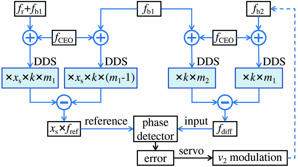
Figure 1.RF signal processing scheme for the optical frequency transfer.
Compared with the previous work on the transfer of laser frequency, in this scheme, the frequency relation between the reference laser and the target laser is decomposed to basic RF processing actions, i.e., adding, subtracting, and scaling of RF frequencies. These functions can be realized by simple RF elements, e.g., mixers combined with filters are used to perform the adding and subtracting of frequency, and DDSs are used to scale the RF frequencies. There is no external reference or synthesizer involved in this scheme, and, therefore, the precision and stability of the generated laser’s frequency do not rely on external reference or synthesizers.
3. Experimental Demonstration of the Scheme
To demonstrate the precision of the frequency transfer scheme, two 1560 nm lasers were phase locked to the same 729 nm ultra-stable laser by using the scheme shown in Fig. 1. The optical setup for the experiment is illustrated in Fig. 2. As shown in the figure, a multi-branch Er-doped fiber-based OFC was used to bridge the three lasers. One branch was used to obtain the signal of and . The second branch was used to beat with the 729 nm laser (). Because the center wavelength of the OFC was at about 1.5 µm, the spectrum for the beating of 729 nm was generated by expanding the spectrum of the OFC to about 1460 nm and then frequency doubling to cover the wavelength of 729 nm. The third branch was used to beat with the two 1560 nm lasers. One of the 1560 nm lasers () was frequency pre-locked to a 10 cm long optical resonator to keep the frequency from drifting away. The second 1560 nm laser () was free running, and the frequency was controlled by monitoring the beat frequency with . The two 1560 nm lasers were combined by using a fiber optic coupler. One output of the coupler was sent to beat with the OFC. The second output was sent to a photo detector for measuring the beat frequency between the two lasers.
![]()
Figure 2.Optical set-up for the frequency transfer. FNC, fiber noise cancellation technique was applied to this fiber link; PPLN, periodically poled lithium niobate, which was used to generate the second harmonic of the OFC; EDFA, erbium-doped optical fiber amplifier, which was used to amplify the power of the OFC; HNLF, highly nonlinear fiber, which was used to expand the spectrum of the comb; PD, photodetector; AOM, acousto-optic modulator, which was used to shift the optical frequency; FC, fiber optic coupler, which was used to combine the two 1560 nm lasers.
The repetition frequency of the OFC was about 200 MHz. The and of the OFC were phase locked to RF signals referred to as H-maser. An about 10 MHz RF signal () was generated from . This signal was used as the reference for the frequency counters for later measuring the beating frequency () between the two 1560 nm lasers. The was generated according to Eq. (4), i.e., the left part of Fig. 1 without multiplying . The numbers used to generate the RF signal were the comb mode number and .
was phase locked to by feeding back to the acousto-optic modulator (AOM1) with . The OFC mode number for beating was 960,542. Therefore, . was tuned about 1.2 GHz lower than and phase locked to by feeding back the fast signal to AOM2 and the slow signal to the laser’s piezoelectric transducer (PZT) with . The corresponding OFC mode number was 960,536. Therefore, . From these numbers, the beating frequency () related to and the ratio () between and were calculated to be
After the two lasers were phase locked, the was measured referred to . Because was at the level of gigahertz (GHz), which exceeded the measuring range of the frequency counter, the frequency of the signal was divided by 64 by using two cascading divide-by-eight static dividers HMC434. Symmetricom 3120A with a measuring bandwidth of 0.5 Hz was used as a high-precision counter to measure . The recorded frequency (noted as ) is shown in Fig. 3(a). The figure shows the frequency difference between and . From the data, the average of was calculated to be
![]()
Figure 3.Measured result of the beating frequency between two 1.5 µm transfer lasers. (a) is the frequency difference between fm and Δν/64, and (b) is the corresponding fractional Allan deviation related to ν2.
From this data, the offset of the measured and theoretical beating frequency was calculated to be , which was related to the beating frequency and related to . The fractional instability of the beat frequency is shown in Fig. 3(b). It shows that fractional Allan deviation was and at the averaging time of 1 s and 10,000 s, respectively.
The frequency ratio between and () was also measured to double check the precision of the transfer scheme. was measured according to Eqs. (2) and (3). The and for and (noted as and ) were generated according to the left and right parts of the scheme shown in Fig. 1 with , respectively. The for the two lasers was obtained by dividing the measured frequency referred to (noted as ) with 10 MHz (noted as ). The recorded is shown in Fig. 4(a). From the figure, the statistic of was calculated to be . Therefore, , and the ratio was
![]()
Figure 4.Frequency ratio of the two transfer lasers measured over the same OFC: (a) the measured value of fdiff2 (fdm), (b) the corresponding Allan deviation of Rm.
Because there was only one OFC available in our laboratory, the measurement of the ratio between the two 1.5 µm lasers was carried out by using the same beating signal as the comb. This result on the ratio demonstrated only the precision and consistency of the RF processing and frequency locking electronics.
In the transfer experiment, two different branches of the OFC were used to beat with the source laser () and the target lasers ( and ). The inter-branch frequency noise introduced by the non-common mode fiber of the OFC might reduce the transfer accuracy and stability. The frequency transfer was expected to be optimized by using a single branch of the OFC or introducing the inter-branch noise cancellation scheme[
4. Conclusion
We transferred the frequency of a clock laser at 729 nm to 1.5 µm in the telecommunication band at an accurate frequency ratio for remote clock comparison. To demonstrate the precision of the frequency transferring process, two 1560 nm lasers were phase locked to the 729 nm laser with slightly different frequency ratios. The relative uncertainty of the frequency difference and frequency ratio between the two transfer lasers were measured to be and in one day’s data acquisition, respectively. This result suggests that the transfer stability and accuracy of our setup are enough for remote frequency comparison of optical clocks at the level of .
References
[1] D. G. Matei, T. Legero, S. Häfner, C. Grebing, R. Weyrich, W. Zhang, L. Sonderhouse, J. M. Robinson, J. Ye, F. Riehle, U. Sterr. 1.5 µm lasers with sub-10 mHz linewidth. Phys. Rev. Lett., 118, 263202(2017).
[2] E. Oelker, R. Hutson, C. Kennedy, L. Sonderhouse, T. Bothwell, A. Goban, D. Kedar, C. Sanner, J. Robinson, G. Marti, D. G. Matei, T. Legero, M. Giunta, R. Holzwarth, F. Riehle, U. Sterr, J. Ye. Demonstration of 4.8 × 10⁻¹⁷ stability at 1 s for two independent optical clocks. Nat. Photonics, 13, 714(2019).
[3] J. M. Robinson, E. Oelker, W. R. Milner, W. Zhang, T. Legero, D. G. Matei, F. Riehle, U. Sterr, J. Ye. Crystalline optical cavity at 4 K with thermal-noise-limited instability and ultralow drift. Optica, 6, 240(2019).
[4] C. Lisdat, G. Grosche, N. Quintin, C. Shi, S. M. F. Raupach, C. Grebing, D. Nicolodi, F. Stefani, A. Al-Masoudi, S. Dörscher, S. Häfner, J.-L. Robyr, N. Chiodo, S. Bilicki, E. Bookjans, A. Koczwara, S. Koke, A. Kuhl, F. Wiotte, F. Meynadier, E. Camisard, M. Abgrall, M. Lours, T. Legero, H. Schnatz, U. Sterr, H. Denker, C. Chardonnet, Y. Le Coq, G. Santarelli, A. Amy-Klein, R. Le Targat, J. Lodewyck, O. Lopez, P.-E. Pottie. A clock network for geodesy and fundamental science. Nat. Commun., 7, 12443(2016).
[5] J. Grotti, S. Koller, S. Vogt, S. Hafner, U. Sterr, C. Lisdat, H. Denker, C. Voigt, L. Timmen, A. Rolland, F. N. Baynes, H. S. Margolis, M. Zampaolo, P. Thoumany, M. Pizzocaro, B. Rauf, F. Bregolin, A. Tampellini, P. Barbieri, M. Zucco, G. A. Costanzo, C. Clivati, F. Levi, D. Calonico. Geodesy and metrology with a transportable optical clock. Nat. Phys., 14, 437(2018).
[6] Frequency ratio measurements at 18-digit accuracy using an optical clock network. Nature, 591, 564(2021).
[7] L.-S. Ma, P. Jungner, J. Ye, J. L. Hall. Delivering the same optical frequency at two places: accurate cancellation of phase noise introduced by an optical fiber or other time-varying path. Opt. Lett., 19, 1777(1994).
[8] K. Predehl, G. Grosche, S. M. F. Raupach, S. Droste, O. Terra, J. Alnis, T. Legero, T. W. Hänsch, T. Udem, R. Holzwarth, H. Schnatz. A 920-kilometer optical fiber link for frequency metrology at the 19th decimal place. Science, 336, 441(2012).
[9] S. Droste, F. Ozimek, T. Udem, K. Predehl, T. W. Hänsch, H. Schnatz, G. Grosche, R. Holzwarth. Optical-frequency transfer over a single-span 1840 km fiber link. Phys. Rev. Lett., 111, 110801(2013).
[10] S. M. Raupach, A. Koczwara, G. Grosche. Brillouin amplification supports 1 × 10⁻²⁰ uncertainty in optical frequency transfer over 1400 km of underground fiber. Phys. Rev. A, 92, 021801(2015).
[11] L.-S. Ma, Z. Bi, A. Bartels, L. Robertsson, M. Zucco, R. S. Windeler, G. Wilpers, C. Oates, L. Hollberg, S. A. Diddams. Optical frequency synthesis and comparison with uncertainty at the 10−19 level. Science, 303, 1843(2004).
[12] H. R. Telle, B. Lipphardt, J. Stenger. Kerr-lens, mode-locked lasers as transfer oscillators for optical frequency measurements. Appl. Phys. B, 74, 1(2002).
[13] D. Nicolodi, B. Argence, W. Zhang, R. Le Targat, G. Santarelli, Y. Le Coq. Spectral purity transfer between optical wavelengths at the 10−18 level. Nat. Photonics, 8, 219(2014).
[14] Y. Yao, Y. Jiang, H. Yu, Z. Bi, L. Ma. Optical frequency divider with division uncertainty at the 10−21 level. Nat. Sci. Rev., 3, 463(2016).
[15] E. Benkler, B. Lipphardt, T. Puppe, R. Wilk, F. Rohde, U. Sterr. End-to-end topology for fiber comb based optical frequency transfer at the 10−21 level. Opt. Express, 27, 36886(2019).
[16] J. Stenger, H. Schnatz, C. Tamm, H. R. Telle. Ultraprecise measurement of optical frequency ratios. Phys. Rev. Lett., 88, 073601(2002).
[17] K. Cui, S. Chao, C. Sun, S. Wang, P. Zhang, Y. Wei, J. Cao, H. Shu, X. Huang. Evaluation of the performance of a 40Ca+ − 27Al+ optical clock(2020).
[18] B. Zhang, Y. Huang, Y. Hao, H. Zhang, M. Zeng, H. Guan, K. Gao. Improvement in the stability of a 40Ca+ ion optical clock using the Ramsey method. J. Appl. Phys., 128, 143105(2020).
[19] Y. Huang, B. Zhang, M. Zeng, Y. Hao, H. Zhang, H. Guan, Z. Chen, M. Wang, K. Gao. A liquid nitrogen-cooled Ca+ optical clock with systematic uncertainty of 3 × 10⁻¹⁸(2021).
[20] J. Zhang, K. Deng, J. Luo, Z. Lu. Direct laser cooling Al+ ion optical clocks. Chin. Phys. Lett., 34, 050601(2017).
[21] K. Kashiwagi, Y. Nakajima, M. Wada, S. Okubo, H. Inaba. Multi-branch fiber comb with relative frequency uncertainty at 10−20 using fiber noise difference cancellation. Opt. Express, 26, 8831(2018).

Set citation alerts for the article
Please enter your email address
© Copyright 2018-2021 | Chinese Laser Press. All Rights Reserved 沪ICP备15018463号-20