
Yu Li, Xinhao Fan, Xuyue Guo, Yi Zhang, Sheng Liu, Bingyan Wei, Dandan Wen, Peng Li, Jianlin Zhao. Metasurface for oscillatory spin splitting along the optical path[J]. Photonics Research, 2022, 10(9): B7
- Photonics Research
- Vol. 10, Issue 9, B7 (2022)
Abstract
1. INTRODUCTION
The control of photon spin as an additional degree of freedom for information transport has generated enormous interest. As a typical phenomenon resulting from photon spin manipulation, the spin splitting of light, namely, spin Hall effect of light [1], which amounts to a coupling between the spin and spatial degrees of freedom [2], has attracted rapidly increasing attention for routing the dynamics of spinning photons [3–15], promising unique applications in optical communications, metrology, and quantum information processing [16,17]. The spin splitting of light was firstly pioneered, to the best of our knowledge, by Onoda for explaining the intriguing phenomenon of the Imbert–Fedorov shift [1] and was experimentally demonstrated by Hosten and Kwiat [18]. Various gradient-index materials referring to spin redirection have been demonstrated to support the spin splitting of light [4,19–25]. However, this spin splitting of light is traditionally tiny because of the exceedingly small photon momentum and spin-orbit coupling (SOC). The exploration of such a weak process relies on the accumulation effect enabled by multiple reflections [26] or ultrasensitive weak measurement method [18].
Metasurfaces made of 2D arrays of anisotropic units [27], by which an abrupt change of the in-plane phase of incident light can be realized, provide dramatically enhanced SOC and sharply changed trajectory of spin photons [28,29]. A wide variety of investigations on manipulating the splitting of spin photons have been carried out based on diverse metasurfaces [30–38]. The advantage of flexibility makes metasurfaces support arbitrary Pancharatnam–Berry (PB) phase [39], as well as the combined effect of PB phase and propagation phase [40], which allows the control of spin splitting of light in multidimensional spaces [41–44]. As the counterpart of the spinning electron, a photon has excellent coherence length, which makes it possible to break the manipulation limitations and dynamics of the spin current. However, the present devices for photon spin manipulation, including optical metasurfaces, can only achieve monotonous routing, that is, the single splitting of spin photons, by some well-known effects such as photonic spin Hall effect or Rashba effect [2]. Most recently, metasurfaces for on-demand polarization transformations along the optical path have evoked the manipulation interest of spin photons in a new spatial dimension [45,46].
Here, we propose a design of dielectric metasurfaces that enable oscillatory spin splitting of light along the optical path. This metasurface consists of two channels, where the photonic spin mode transition introduces modulation phases that actuate two spin modes to focus and generate path-dependent interference, resulting in oscillatory focusing and defocusing behaviors depending on the chiral PB phase shifts within two pathways [47]. Under the normal incidence of a linearly polarized beam, the PB phase shift removes the spin degeneracy in the interference and induces the lateral spin splitting of light with alternately variant transport direction along the propagating path. This scheme is valid, as the oscillatory spin splitting is invariant for the incidences of linearly polarized light beams with different orientations. Our scheme may offer a new route to manipulate spin-orbit interaction related photons.
Sign up for Photonics Research TOC. Get the latest issue of Photonics Research delivered right to you!Sign up now
2. THEORY
In the experimental demonstration of the Aharonov–Bohm (AB) effect [48], the electron beams are diffracted from two pathways and then interfere to produce spatially oscillatory electron density, which spatially shifts under the modulation of AB phase associated with enclosed magnetic flux, with respect to free propagation [47,49]. More relevantly, in photonic systems, e.g., optical waveguide, where the phases of dynamic modulation are considered as effective gauge potentials without magnetic field [50,51], optical AB effects have been observed and used to govern guiding mode coupling and interference, achieving remarkable phenomena such as nonmagnetic optical isolation and temporally oscillatory signals [52–55]. Similarly, another geometric phase, the well-known PB phase, is used here to induce spatially oscillatory spin density that only depends on the enclosed PB phase shift.
Figure 1(a) illustrates a metasurface that serves as an optical interferometer, which consists of two coaxially annular channels. The aperture of channel is , and the inner and outer radii of channel are and , respectively. For the incidence of light beams with spin states, the meta-atoms that are equivalent half-wave plates transform them into opposite spin states. Here, we consider two spin states as two modes in parameter space. Consequently, the right-handed circular polarization (RCP) and left-handed circular polarization (LCP) are denoted by photonic modes and , respectively. Figures 1(b) and 1(c) illustrate such an effective photonic transition taken on the Poincaré sphere. As is shown, the meta-atom converts the incident RCP into LCP, that is, from photonic mode to . Besides the propagation phase (denoted as ) accumulated from the waveguide effect of the meta-atom, the outgoing photons acquire an additional phase, namely, the PB phase, which is denoted as , where is the rotation angle of the birefringent meta-atom [49]. Therefore, the concomitant phase arising from the spin state transition is . Supposing that meta-atoms in two channels have different rotation angles denoted as and , respectively, the PB phase shift between the photons in two pathways is . Otherwise, the PB phase shift of outgoing photons is opposite, i.e., , when the photonic mode is transformed to .
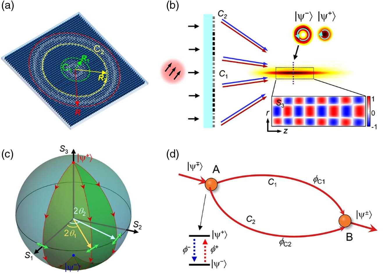
Figure 1.Illustration of metasurface interferometer for oscillatory spin splitting of light. (a) Sketch of the dielectric metasurface with two coaxial channels. (b) Schematic of RCP and LCP transforming and guiding via the metasurface with distinct modulation phases.
For charged particles, phase has been turned out to be a special case of geometric phase and is proportional to the closed magnetic flux of path loop , i.e., , where denotes the vector potential associated with the magnetic field. Likewise, here we can associate an analogous potential for the photonic system. The independent interference manipulations based on analogous potential are depicted in Fig. 1(d). After the spin state transitions at location A, two transmitted fields propagate along separate pathways and under the modulation of global phases and then interfere at location , so the phase difference between these two fields is then
For the metasurface, we are free to choose a gauge. For example, we can define a focusing phase as . For this special case, . The spin density distribution in general depends only on such a line integral of PB phases on the closed path as follows:
Clearly, the spin density distribution is only dependent on the PB shift , indicating that we can address the spin-orbit interaction by manipulating the chiral PB phase shift.
For the incidence of a uniform light beam, whose electric field is denoted as , with and representing the and components, respectively, the separated and transmitted fields from two channels are expressed as , where and represent the transmissions and acquired global phases from two channels, respectively. In the case that is constant and , as well as , fields propagating along two pathways interfere at the same focal plane. Considering the cylindrical symmetry, the interference field can be expressed as the superposition of two zeroth-order Bessel–Gaussian beams with momentum mismatch. Figure 2(a) illustrates their wave vectors in momentum space, where , , and are the transverse and axial wave vector components. The interference field is thus
![]()
Figure 2.Design of the metasurface. (a) Wave vectors of fields in two pathways in the momentum space. (b) Modulation phases
According to Eq. (4), the interference produces oscillatory spin density with a period about , of which the interferogram is modulated by . Note that, due to the conjugate relationship between PB phases of two spin states, once , two spin states present distinct density distribution. For instance, when the RCP produces constructive interference and , the LCP produces destructive interference. Therefore, two spin states produce a bright and a dark spot, respectively, indicating the focusing and defocusing behaviors, as the transverse intensity distribution of two spin states in Fig. 1(b).
After optimizing the parameters, we choose and , so that . In addition, we set , , and , with the focal length and the wavelength. Figure 2(b) shows the modulation phases for two spin states and transmission of the metasurface. Considering the rotational symmetry, here, we plot the distributions along any radius of the metasurface. The solid, dashed, and dotted lines depict the and phases and transmission distributions, respectively.
3. RESULTS
According to the joint effect of PB phase and propagation phase [40], we fabricated and characterized the metasurface. Figure 2(c) schematically shows a meta-atom, which consists of a polycrystalline silicon (Poly-Si) rectangle nanopillar deposited on a glass substrate. The height and period of the nanopillar are and , respectively, and the refractive index is . We selected 16 geometric configurations meeting the combined condition, that is, two linearly polarized eigenstates ( and ) keep phase retardation difference, i.e., , while the propagation phase increases linearly in an interval of , i.e., . Figure 2(d) maps these selected configurations in the transmission amplitude diagram. Figure 2(e) displays the propagation phase and retardation difference , as well as transmission amplitudes of two eigenstates corresponding to these 16 configurations. In addition, for the opaque regions, where and , we picked out a configuration with near-zero transmission amplitude, i.e., . Its geometric parameters are and . Figure 2(f) shows simulated magnetic energy density distributions of this element with periodic boundary conditions and rotation angle , when - and -polarized lights illuminate the element. We fabricated the metasurface with transmission-type configuration by using standard electron-beam lithography and inductively coupled plasma etching.
Figures 3(a) and 3(b) display the optical and scanning electron microscope images of the fabricated sample and its local structures, respectively. The sample is composed of elements with a lattice constant of 400 nm along the and axes. The experimental setup is shown in Fig. 3(c). The light beam from a diode laser with wavelength of normally illuminates the metasurface after passing through a half-wave plate. The focal field and oscillatory spin splitting are then observed by a detecting system, which consists of a magnifying microscope objective, a quarter-wave plate, a linear polarizer, and a CCD camera. In experiments, the metasurface is placed on a linear translation stage to implement the scan. The half-wave plate is used to rotate the orientation of the linearly polarized light beam. The quarter-wave plate and polarizer are used to measure the Stokes parameters. The inset illustrates a scanning electron microscope image of local structures in two channels.
![]()
Figure 3.Sketch of experimental setup. (a) Optical and (b) scanning electron microscope images of the metasurface and its local structure. The sample is composed of
Figure 4(a) shows the measured 3D intensity distribution of the focal field, when the metasurface is illuminated by a horizontally polarized light beam. As shown, the focal field presents a consecutive configuration with the transverse and longitudinal widths (full width at half-maximum) of about 9 μm and 800 μm, respectively. Figure 4(b) displays the transverse intensity patterns in two planes denoted by dashed lines in Fig. 4(a). As expected, two spin states present variant divergence and convergence. Hence, radial spin splitting occurs at these planes with opposite spin transport directions. These slices in Fig. 4(c) illustrate the variation of spin angular momentum density, which is generally characterized by the third Stokes parameter, i.e., , with a proportional relation of . Here, depicts the unit vector in the momentum direction [56]. Red and blue represent the and states, respectively. As is shown, two spin states of light split in the transverse direction, then revert and reversely split along the longitudinal direction alternately. That is, the spin splitting oscillates along the longitudinal direction, with an interval of transport direction depending on the spatial mode mismatch. In such a monitoring range, this radial splitting with opposite transports alternately occurs twice, with a period about 160 μm. It is worth noting that the oscillating period varies slightly with the increasing distance from the focal plane.
![]()
Figure 4.Observation of oscillatory spin splitting of light along the optical path. (a) Measured 3D intensity distribution of the focal field for the incidence of a linearly polarized field. The red dashed lines depict the
To further analyze the invariance of this oscillation, we consider the transformation of modulation phase and design another metasurface, whose propagation phases and PB phases are , , and , . For this transformation, the PB phase shifts of two spin states are 0 and π, respectively. However, the relative PB phase shift is invariant, i.e., . Figures 5(a) and 5(b) display the measured on-axis distributions for the incidences of different linearly polarized light beams, where I and II correspond to two metasurfaces with distinct PB phases, the subscripts , , and A depict the horizontal, vertical, and antidiagonal directions, respectively. These results demonstrate that, under the same PB phase shift, the oscillatory spin splitting of light is independent of the incident polarization. Moreover, when the relationship of spin-dependent PB phase shift is constant, keeps oscillating but with an overall translation of a quarter period along the direction, indicating the robustness of this oscillation phenomenon. Moreover, the invariant property of this spin splitting is independent of the propagation phase. Attributed to the primary effect of PB phase on spin interference, our scheme is applicable to other optical bands and even other kinds of waves. The efficiencies of these two metasurfaces are about 25%.
![]()
Figure 5.Measured on-axis Stokes parameter
4. DISCUSSION
The potential of our approach is not limited to the above discussions. It offers new routes for manipulating photon spin via other types of metasurfaces, as well as other interference systems [2], such as optical waveguides, evanescent interfaces, and high-numerical-aperture focusing lenses, where the spin-orbital interaction of light occurs as an inherent phenomenon. The combination of oscillatory spin splitting with the advantages of extremely reduced spatial scale and enhanced intensity in these systems has promising prospects in applications such as enhanced circular dichroism [57,58].
As the optical trapping commences with distribution of the light field, tailoring the distribution of the field is a direct way to modulate the optical force and trapping results. This metasurface provides multiple polarization-selected focal fields with ingenious intensity and spin angular momentum structures. On the one hand, in the case of LCP or RCP incidence, the focal field presents alternately focusing and defocusing spots along the propagation direction with the RCP or LCP state, namely, optical-cage-type intensity morphology in 3D space. Consequently, the particles with different refractive indices can be trapped in these focusing and defocusing nodes, respectively. Since these nodes are spin-switchable, the trapping of different particles can be selected by steering the incident spin states [59]. On the other hand, in the case of linear polarization incidence, the longitudinally space-varying spin density of the light field empowers the spin-dependent light–matter interaction, allowing the separation substances by their chirality [60,61]. Specially, transverse chiral optical forces induced by elaborate optical helicity gradients have been demonstrated in application of chirality-sensitive sorting [62]. Likewise, here, for the incidence of linearly polarized light, the focal field arising from the metasurface has an axial helicity gradient, which could induce forward and backward chiral optical forces. As shown in Fig. 4, this focal field has stable axial helicity gradients without respect to the incident polarization, which may supply a solution to realize chirality-sensitive optical force along the propagation direction [63].
5. CONCLUSION
In this paper, we presented an optical analogue of the effect via a single-layer dielectric metasurface interferometer to realize oscillatory spin splitting of light. The metasurface was designed by the combination of PB phase and propagation phase, which force two spin states of light to focus and interfere, respectively, with independent PB phase shifts. Under the illumination of a linearly polarized light beam, the metasurface induced radial splitting of two spin states and axially oscillating spin density. Besides its fundamental interest, utilizing this metasurface, distinct focal fields with elaborate intensity and polarization structures, e.g., spin-switchable optical chains, and consecutive focal field with axial helicity gradient can be created, which are expected to explore novel applications of optical trapping and chirality sorting.
Acknowledgment
Acknowledgment. We thank Zhiwei Song of National Center for Nanoscience and Technology for supplying the materials as well as the Analytical and Testing Center of Northwestern Polytechnical University.
References
[1] M. Onoda, S. Murakami, N. Nagaosa. Hall effect of light. Phys. Rev. Lett., 93, 083901(2004).
[2] K. Bliokh, F. Rodríguez-Fortuño, F. Nori, A. V. Zayats. Spin-orbit interactions of light. Nat. Photonics, 9, 796-808(2015).
[3] K. Y. Bliokh, A. Aiello. Goos–Hänchen and Imbert–Fedorov beam shifts: an overview. J. Opt., 15, 014001(2013).
[4] X. Ling, X. Zhou, K. Huang, Y. Liu, C. W. Qiu, H. Luo, S. Wen. Recent advances in the spin Hall effect of light. Rep. Prog. Phys., 80, 066401(2017).
[5] , G. Malpuech, M. Glazov. Optical spin Hall effect. Phys. Rev. Lett., 95, 136601(2005).
[6] K. Y. Bliokh, Y. Gorodetski, V. Kleiner, E. Hasman. Coriolis effect in optics: unified geometric phase and spin-Hall effect. Phys. Rev. Lett., 101, 030404(2008).
[7] H. Luo, S. Wen, W. Shu, D. Fan. Spin Hall effect of light in photon tunneling. Phys. Rev. A, 82, 043825(2010).
[8] E. Kammann, T. C. H. Liew, H. Ohadi, P. Cilibrizzi, P. Tsotsis, Z. Hatzopoulos, P. G. Savvidis, A. V. Kavokin, P. G. Lagoudakis. Nonlinear optical spin Hall effect and long-range spin transport in polariton lasers. Phys. Rev. Lett., 109, 036404(2012).
[9] M. Neugebauer, P. Banzer, T. Bauer, S. Orlov, N. Lindlein, A. Aiello, G. Leuchs. Geometric spin Hall effect of light in tightly focused polarization-tailored light beams. Phys. Rev. A, 89, 013840(2014).
[10] K. Y. Bliokh, D. Smirnova, F. Nori. Quantum spin Hall effect of light. Science, 348, 1448-1451(2015).
[11] Y. Zhang, P. Li, S. Liu, J. Zhao. Unveiling the photonic spin Hall effect of freely propagating fan-shaped cylindrical vector vortex beams. Opt. Lett., 40, 4444-4447(2015).
[12] P. Slobozhanyuk, A. N. Poddubny, I. S. Sinev, A. K. Samusev, Y. F. Yu, A. I. Kuznetsov, A. E. Miroshnichenko, Y. S. Kivshar. Enhanced photonic spin Hall effect with subwavelength topological edge states. Laser Photon. Rev., 10, 656-664(2016).
[13] S. Liu, P. Li, Y. Zhang, X. Gan, M. Wang, J. Zhao. Longitudinal spin separation of light and its performance in three-dimensionally controllable spin-dependent focal shift. Sci. Rep., 6, 20774(2016).
[14] W. J. M. Kort-Kamp. Topological phase transitions in the photonic spin Hall effect. Phys. Rev. Lett., 119, 147401(2017).
[15] S. Fu, C. Guo, G. Liu, Y. Li, H. Yin, Z. Li, Z. Chen. Spin-orbit optical Hall effect. Phys. Rev. Lett., 123, 243904(2019).
[16] X. Zhou, X. Ling, H. Luo, S. Wen. Identifying graphene layers via spin Hall effect of light. Appl. Phys. Lett., 101, 251602(2012).
[17] T. Zhu, Y. Lou, Y. Zhou, J. Zhang, J. Huang, Y. Li, H. Luo, S. Wen, S. Zhu, Q. Gong, M. Qiu, Z. Ruan. Generalized spatial differentiation from the spin Hall effect of light and its application in image processing of edge detection. Phys. Rev. Appl., 11, 034043(2019).
[18] O. Hosten, P. Kwiat. Observation of the spin Hall effect of light via weak measurements. Science, 319, 787-790(2008).
[19] K. Y. Bliokh, Y. P. Bliokh. Conservation of angular momentum, transverse shift, and spin Hall effect in reflection and refraction of an electromagnetic wave packet. Phys. Rev. Lett., 96, 073903(2006).
[20] D. Haefner, S. Sukhov, A. Dogariu. Spin Hall effect of light in spherical geometry. Phys. Rev. Lett., 102, 123903(2009).
[21] N. Hermosa, A. M. Nugrowati, A. Aiello, J. P. Woerdman. Spin Hall effect of light in metallic reflection. Opt. Lett., 36, 3200-3202(2011).
[22] Y. Lv, Z. Wang, Y. Jin, M. Cao, L. Han, P. Zhang, H. Li, H. Gao, F. Li. Spin polarization separation of light reflected at Brewster angle. Opt. Lett., 37, 984-986(2012).
[23] L. J. Kong, X. L. Wang, S. M. Li, Y. Li, J. Chen, B. Gu, H. T. Wang. Spin Hall effect of reflected light from an air-glass interface around the Brewster’s angle. Appl. Phys. Lett., 100, 071109(2012).
[24] J. L. Ren, B. Wang, M. M. Pan, Y. F. Xiao, Q. Gong, Y. Li. Spin separations in the spin Hall effect of light. Phys. Rev. A, 92, 013839(2015).
[25] T. Bardon-brun, D. Delande, N. Cherroret. Spin Hall effect of light in a random medium. Phys. Rev. Lett., 123, 043901(2019).
[26] K. Y. Bliokh, A. Niv, V. Kleiner, E. Hasman. Geometrodynamics of spinning light. Nat. Photonics, 2, 748-753(2008).
[27] H. T. Chen, A. J. Taylor, N. Yu. A review of metasurfaces: physics and applications. Rep. Prog. Phys., 79, 076401(2016).
[28] X. Yin, Z. Ye, J. Rho, Y. Wang, X. Zhang. Photonic spin Hall effect at metasurfaces. Science, 339, 1405-1407(2013).
[29] X. Ling, X. Zhou, X. Yi, W. Shu, Y. Liu, S. Chen, H. Luo, S. Wen, D. Fan. Giant photonic spin Hall effect in momentum space in a structured metamaterial with spatially varying birefringence. Light Sci. Appl., 4, e290(2015).
[30] N. Shitrit, I. Bretner, Y. Gorodetski, V. Kleiner, E. Hasman. Optical spin Hall effects in plasmonic chains. Nano Lett., 11, 2038-2042(2011).
[31] L. Huang, X. Chen, B. Bai, Q. Tan, G. Jin, T. Zentgraf, S. Zhang. Helicity dependent directional surface plasmon polariton excitation using a metasurface with interfacial phase discontinuity. Light Sci. Appl., 2, e70(2013).
[32] N. Shitrit, I. Yulevich, E. Maguid, D. Ozeri, D. Veksler, V. Kleiner, E. Hasman. Spin-optical metamaterial route to spin-controlled photonics. Science, 340, 724-726(2013).
[33] , J. Liu, A. Kildishev, V. Shalaev. Photonic spin Hall effect in gap–plasmon metasurfaces for on-chip chiroptical spectroscopy. Optica, 2, 860-863(2015).
[34] W. Luo, S. Xiao, Q. He, S. Sun, L. Zhou. Photonic spin Hall effect with nearly 100% efficiency. Adv. Opt. Mater., 3, 1102-1108(2015).
[35] Y. Liu, Y. Ke, H. Luo, S. Wen. Photonic spin Hall effect in metasurfaces: a brief review. Nanophotonics, 6, 51-70(2016).
[36] X. G. Luo, M. B. Pu, X. Li, X. L. Ma. Broadband spin Hall effect of light in single nanoapertures. Light Sci. Appl., 6, e16276(2017).
[37] M. Kim, D. Lee, T. H. Kim, Y. Yang, H. J. Park, J. Rho. Observation of enhanced optical spin Hall effect in a vertical hyperbolic metamaterial. ACS Photon., 6, 2530-2536(2019).
[38] K. Chaudhuri, A. Shaltout, D. Shah, U. Guler, A. Dutta, V. M. Shalaev, A. Boltasseva. Photonic spin Hall effect in robust phase gradient metasurfaces utilizing transition metal nitrides. ACS Photon., 6, 99-106(2019).
[39] J. Li, S. Kamin, G. Zheng, F. Neubrech, S. Zhang, N. Liu. Addressable metasurfaces for dynamic holography and optical information encryption. Sci. Adv., 4, eaar6768(2018).
[40] J. P. B. Mueller, N. A. Rubin, R. C. Devlin, B. Groever, F. Capasso. Metasurface polarization optics: independent phase control of arbitrary orthogonal states of polarization. Phys. Rev. Lett., 118, 113901(2017).
[41] J. Zhou, H. Qian, G. Hu, H. Luo, S. Wen, Z. Liu. Broadband photonic spin Hall meta-lens. ACS Nano, 12, 82-88(2018).
[42] Z. Zhang, D. Wen, C. Zhang, M. Chen, W. Wang, S. Chen, X. Chen. Multifunctional light sword metasurface lens. ACS Photon., 5, 1794-1799(2018).
[43] S. Li, X. Li, G. Wang, S. Liu, L. Zhang, C. Zeng, L. Wang, Q. Sun, W. Zhao, W. Zhang. Multidimensional manipulation of photonic spin Hall effect with a single-layer dielectric metasurface. Adv. Opt. Mater., 7, 1801365(2019).
[44] R. Jin, L. Tang, J. Li, J. Wang, Q. Wang, Y. Liu, Z.-G. Dong. Experimental demonstration of multidimensional and multifunctional metalenses based on photonic spin Hall effect. ACS Photon., 7, 512-518(2020).
[45] H. Dorrah, N. A. Rubin, A. Zaidi, M. Tamagnone, F. Capasso. Metasurface optics for on-demand polarization transformations along the optical path. Nat. Photonics, 15, 287-296(2021).
[46] H. Dorrah, N. A. Rubin, M. Tamagnone, A. Zaidi, F. Capasso. Structuring total angular momentum of light along the propagation direction with polarization-controlled meta-optics. Nat. Commun., 12, 6249(2021).
[47] R. G. Chambers. Shift of an electron interference pattern by enclosed magnetic flux. Phys. Rev. Lett., 5, 3-5(1960).
[48] Y. Aharonov, D. Bohm. Significance of electromagnetic potentials in the quantum theory. Phys. Rev., 115, 485(1959).
[49] E. Cohen, H. Larocque, F. Bouchard, F. Nejadsattari, Y. Gefen, E. Karimi. Geometric phase from Aharonov–Bohm to Pancharatnam–Berry and beyond. Nat. Rev. Phys., 1, 437-449(2019).
[50] Y. Lumer, M. A. Bandres, M. Heinrich, L. J. Maczewsky, H. Herzig-Sheinfux, A. Szameit, M. Segev. Light guiding by artificial gauge fields. Nat. Photonics, 13, 339-345(2019).
[51] Y. Chen, R. Y. Zhang, Z. Xiong, Z. Xiong, Z. H. Hang, J. Li, J. Q. Shen, C. T. Chan. Non-Abelian gauge field optics. Nat. Commun., 10, 3125(2019).
[52] K. Fang, Z. Yu, S. Fan. Photonic Aharonov-Bohm effect based on dynamic modulation. Phys. Rev. Lett., 108, 153901(2012).
[53] E. Li, B. J. Eggleton, K. Fang, S. Fan. Photonic Aharonov–Bohm effect in photon–phonon interactions. Nat. Commun., 5, 3225(2014).
[54] F. Liu, J. Li. Gauge field optics with anisotropic media. Phys. Rev. Lett., 114, 103902(2015).
[55] M. Parto, H. Lopez-Aviles, J. E. Antonio-Lopez, M. Khajavikhan, R. Amezcua-Correa, D. N. Christodoulides. Observation of twist-induced geometric phases and inhibition of optical tunneling via Aharonov-Bohm effects. Sci. Adv., 5, eaau8135(2019).
[56] L. Allen, M. W. Beijersbergen, R. J. C. Spreeuw, J. P. Woerdman. Orbital angular momentum of light and the transformation of Laguerre-Gaussian laser modes. Phys. Rev. A, 45, 8185-8189(1992).
[57] H. Hu, Q. Gan, Q. Zhan. Generation of a nondiffracting superchiral optical needle for circular dichroism imaging of sparse subdiffraction objects. Phys. Rev. Lett., 122, 223901(2019).
[58] M. Hentschel, M. Schäferling, X. Duan, H. Giessen, N. Liu. Chiral plasmonics. Sci. Adv., 3, e1602735(2017).
[59] Y. Zhao, Q. Zhan, Y. Zhang, Y. P. Li. Creation of a three-dimensional optical chain for controllable particle delivery. Opt. Lett., 30, 848-850(2005).
[60] M. H. Alizadeh, B. M. Reinhard. Transverse chiral optical forces by chiral surface plasmon polaritons. ACS Photon., 2, 1780-1788(2015).
[61] D. Ayuso, O. Neufeld, A. F. Ordonez, P. Decleva, G. Lerner, O. Cohen, M. Ivanov, O. Smirnova. Synthetic chiral light for efficient control of chiral light–matter interaction. Nat. Photonics, 13, 866-871(2019).
[62] N. Kravets, A. Aleksanyan, E. Brasselet. Chiral optical Stern-Gerlach Newtonian experiment. Phys. Rev. Lett., 122, 024301(2019).
[63] X. Wang, Y. Dai, Y. Zhang, C. Min, X. Yuan. Plasmonic manipulation of targeted metallic particles by polarization-sensitive metalens. ACS Photon., 5, 2945-2950(2018).

Set citation alerts for the article
Please enter your email address
© Copyright 2018-2021 | Chinese Laser Press. All Rights Reserved 沪ICP备15018463号-20