
Angela I. Barreda, Mario Zapata-Herrera, Isabelle M. Palstra, Laura Mercadé, Javier Aizpurua, A. Femius Koenderink, Alejandro Martínez. Hybrid photonic-plasmonic cavities based on the nanoparticle-on-a-mirror configuration[J]. Photonics Research, 2021, 9(12): 2398
- Photonics Research
- Vol. 9, Issue 12, 2398 (2021)
Abstract
1. INTRODUCTION
Optical cavities are structures tailored to localize light in small volumes during long residence times. To quantify light–matter interaction in optical cavities, a key metric is the Purcell factor () [1–3], which is proportional to the ratio between the quality factor (or factor) and the effective volume of the cavity mode, quantifying the local density of optical states (LDOS) at resonance [4,5]
In the last few years, hybrid plasmonic-photonic cavities [10,12–21] have emerged as a promising way of mixing both types of confinement approaches, taking advantage of the idea of placing a plasmonic nanoantenna in a large field confinement region of a dielectric cavity where both modes, plasmonic and photonic, can hybridize. This results in new features not attainable by either plasmonic or photonic cavities when operating individually. Interestingly, such cavities enable engineering the LDOS by properly tailoring the coupling between the plasmonic and photonic modes so that the factor and the normalized mode volume can be tuned [16]. This also allows us to harness the value of the Purcell factor so that it can be suitably chosen for different applications in classical and quantum optics. For the latter, previous works have mainly focused on single-photon sources, low-threshold lasers, strong coupling with quantum emitters, or sensing and vibrational spectroscopy [16,22–25].
Among the different possible implementations of such hybrids, the integration of bow-tie nanoantennas as canonical plasmonic structures on dielectric photonic crystal cavities has a set of advantages [16], such as the low value of the mode volume of the photonic cavity and the possibility of fabrication using conventional lithography methods. Noticeably, such hybrid cavities have not yet witnessed an experimental demonstration, although several experiments have confirmed the integration of bow-tie nanoantennas in dielectric waveguides [26–31]. A main limitation of this hybrid plasmonic-photonic cavity approach is that the bow-tie gap is defined by lithography, which limits its minimum attainable value. Whilst reaching gap widths below 10 nm is attainable [32–34], repeatability is very poor: given a same nominal value, the obtained gap width is extremely dependent on the local conditions and can take different values—or get closed—for different bow-tie nanoantennas, even when fabricated in same lithography step [27,34]. In general, reaching nm and sub-nm plasmonic gaps in a controllable fashion becomes extremely complex and hardly reconcilable with the multistep lithography challenge of integration with photonic cavities.
Sign up for Photonics Research TOC. Get the latest issue of Photonics Research delivered right to you!Sign up now
A much more appealing approach to reach nm- and sub-nm-scale plasmonic gaps in a repeatable way is by vertical deposition. Within this paradigm, nanoparticle-on-a-mirror (NPoM) plasmonic cavities have demonstrated unrivalled performance in extreme spatial field confinement [35–37]. The smallest demonstration of mode volume so far has been in picocavities, where the electromagnetic field is ultimately confined around a single metallic atom [9,38,39]. By using molecular monolayers, or atomically thin layers, so-called nanocavities can be routinely achieved, i.e., mode volumes .
In order to hybridize such gap modes as exist in vertically assembled NPoM structures with a photonic crystal cavity, one would require a confined photonic mode with the main component of the electric field pointing along the vertical direction. This requires a photonic bandgap for transverse magnetic (TM) modes, which can be achieved by drilling holes in a thick nanobeam with a high index of refraction [40,41]. In this work, we introduce a novel class of hybrid cavity resulting from the hybridization between a metallic nanoparticle and a photonic crystal cavity in a high-index nanobeam that supports a highly confined TM mode at . We show that the upper surface of the photonic crystal can act as a low-reflectivity mirror when the metallic nanoparticle is placed on top of it. For nanoparticle-mirror gaps () around 1 nm and through numerical calculations of the LDOS, we observe a strong reduction of the mode volume without a significant impairment of the factor of the photonic cavity. Compared to the Purcell factors acquired with feasible gaps () for hybrid plasmonic-photonic configurations obtained from TE photonic modes, we reach an improvement of 1 order of magnitude. We also discuss the possible experimental design, which would require the use of materials with high index of refraction () and negligible losses at visible and near-infrared spectral ranges, with gallium phosphide as a feasible candidate.
2. DESCRIPTION OF THE HYBRID SYSTEM
The system under study in this work is schematically depicted in the top panel of Fig. 1 [Fig. 1(a)]: a metal nanoparticle is placed on top of a one-dimensional photonic crystal cavity created in a high-index dielectric nanobeam. These two elements are depicted separately in Figs. 1(b) and 1(c). The goal of the hybridization is to improve the quality factor of the plasmonic nanoparticle by suppressing scattering pathways as a result of the photonic bandgap of the dielectric cavity, and to simultaneously decrease the mode volume of the dielectric cavity by squeezing the field with the metal nanoparticle. Note that, unlike in the standard NPoM configuration where the mirror is a metallic surface, in the proposed hybrid structure, it is the upper interface of the photonic crystal that acts as a mirror. This means that a high index of refraction is required to increase the reflectivity of the interface and boost the light confinement in the spacing gap. Moreover, in the current scheme, extreme light confinement will take place for the electric field pointing from the upper interface toward the metal nanoparticle. This means that the dielectric cavity must operate for TM polarization (or odd-parity modes in the context of photonic crystal slabs [42,43]). Obtaining odd-parity photonic bandgaps is not easy in thin semiconductor nanobeams drilled by holes, which usually tend to have bandgaps for transverse-electric (TE) modes [42,44]. However, by using thick substrates made of high-index dielectric materials (such as silicon at telecom wavelengths), the realization of high-Q cavities for odd (or TM) modes by drilling holes becomes feasible [40,41]. Nevertheless, in order to operate at visible or near-infrared wavelengths, where many applications in the contexts of cavity quantum electrodynamics can be found, silicon is not allowed, and there are not so many transparent materials with a large index of refraction. Recently, gallium phosphide has been suggested as an interesting optical material for nonlinear [45] or optomechanical [46] applications. Interestingly, it shows a large refractive index () and is transparent at wavelengths over . For those reasons, this is the material that we have chosen to implement the photonic crystal cavity. In order to evaluate the effects of the dielectric substrate on the optical properties of the metal nanoparticle (when placed in its close proximity), we also consider the intermediate system depicted in Fig. 1(d). The analysis of this structure will allow us to separate the effects induced by the nonstructured dielectric substrate, merely acting as a “bad” mirror, and the whole perforated cavity having a bandgap for TM-polarized light.
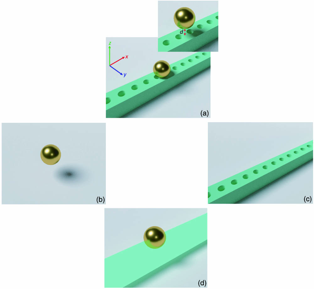
Figure 1.Conceptual scheme of the hybrid system under study. (a) A metallic nanoparticle is placed on top of a dielectric cavity. Both structures are spaced by a tiny gap of thickness
3. METHODS
The results are calculated by means of the finite element method (FEM), implemented in the commercial software COMSOL Multiphysics [47]. Using the Radio Frequency Module in COMSOL, the Maxwell equations together with the boundary conditions are solved in the frequency domain. The optical constants for gold nanoparticles are taken from Ref. [48]. The refractive index for gallium phosphide (GaP) is . To rigorously determine the LDOS, the structure is illuminated by an electric point-dipole source, whose dipole moment is considered along the axis (along the axis connecting the sphere and the cavity). The normalized LDOS is defined as
4. RESULTS
We start by considering the electromagnetic response of an isolated metallic nanosphere, which for small radius exhibits a dipolar plasmonic response at visible wavelengths. In Fig. 2(a), we show the calculated normalized LDOS for a gold nanosphere of radius , which displays a dipolar electric resonance at . In analogy to Ref. [16], LDOS values are normalized to the LDOS in a vacuum at the same wavelength, with LDOS containing radiative as well as nonradiative contributions. It is worth noting that, although in the text we write LDOS, rigorously, this magnitude corresponds to partial LDOS (PLDOS) and not to LDOS, as the emitter is not only sensitive to the intensity of the available modes but also to their polarization. A dipole aligned along the axis will interact most strongly with those modes where the electric field is polarized in the same direction [49]. The optical quality factor (retrieved by means of a Fano line shape fitting; in Appendix C, an explanation is provided of the performed fittings in the work, together with their equations) and the normalized mode volume are shown in the inset. While only LDOS is a rigorous physical quantity, it has become practice in the field to interpret near-Lorentzian LDOS peaks in terms of and , simply by reading of from the line shape and inverting peak LDOS into a volume via Eq. (1). We follow this practice in this work, always quoting LDOS, , and derived together. This practice is adopted only for qualitative practical comparison with other resonators and does not imply any endorsement of the concept of Purcell factor and mode volume for open, lossy, or multimode resonators. The term “mode volume” here is not used as an endorsement of the validity of this concept per se for plasmonics, and the term also does not indicate that we employed a quasi-normal mode formalism. Noticeably, becomes very small; as expected from plasmonic cavities, far smaller than the diffraction limit. The extreme confinement is clearly appreciated in Fig. 2(b), which depicts the near-field map corresponding to the component of the electric field under resonance, with linearly polarized light (along the axis) propagating along the axis. This figure corroborates the dipolar character of the excited mode at resonance in Fig. 2(a).
![]()
Figure 2.Simulation results of the different building blocks of the hybrid cavity. (a) Normalized LDOS,
When the photonic crystal cavity is considered, the versus situation is reversed. Our dielectric cavity consists of a gallium phosphide (GaP with refractive index ) nanobeam of width and thickness drilled with circular holes. To build the cavity, we calculate the parameters to get a TM bandgap around (see Appendix D, where we represent the band diagram for the photonic crystal and the defect), which happens for a period and hole radii of . We choose this wavelength because, as shown in previous works [16], the nanoparticle resonance must be blueshifted regarding that of the photonic cavity to improve the performance of the hybrid cavity with respect to the bare components. Nevertheless, the resonance wavelength could be either red- or blue-shifting by changing the parameters defining the photonic crystals. With the previous dimensions, we form two TM mirrors with 10 holes each at every side of the cavity. The photonic cavity is subsequently formed by adiabatically changing the dimensions of the mirrors when moving toward the cavity center, where the nanoparticle will be placed. In particular, we reduce the period and hole size of the photonic crystal during seven holes at each side of the cavity by means of a quadratic adiabatic transition down to and , respectively [40,41]. This leads to a confined TM mode with a large factor as shown in Fig. 2(c), which depicts the obtained normalized LDOS for the isolated photonic cavity, calculated by considering the illumination of an electric dipole placed 0.5 nm above the cavity. From the fitting of the data to a Lorentzian line shape (see Appendix C for an explanation about the fitting and their equations), the factor and normalized mode volume values are extracted. In this case we obtain a large factor (), which could be further engineered to values even above , and a diffraction-limited normalized volume . Looking at the mode profile of the component of the electric field distribution in the cavity at resonance [see Fig. 2(d)] ( crosscut of the cavity design corresponding to the length-thickness plane at the middle of the beam width), we can observe that it has evanescent tails of on top of the upper interface, which may couple to the evanescent field perpendicular to the nanosphere surface [Fig. 2(b)] and thus give rise to the pursued hybridization of the plasmonic and photonic resonances. The field distribution, calculated by using the COMSOL Multiphysics eigenmode solver, corresponds to the fundamental mode. Henceforth, all the near-field maps shown in this work are obtained using this methodology. The tiny oscillations in Figs. 2(a) and 2(c) are related with internal reflections with the PMLs in the implemented simulation box and correspond to numerical noise. Since the spectral position of the peak and its width as well as convergence are achieved, we assume these numerical artefacts are small enough to be considered in our main results.
In order to estimate the effect of the dielectric layer acting as a low-reflectivity mirror, we also simulate the response of the metallic nanosphere when located on the top of a nonstructured GaP nanobeam (width and thickness ) to determine the influence of the dielectric substrate on the electromagnetic behavior of the gold nanoparticles. In other words, we simulated the same geometry as in the case of the hybrid cavity (below) but without holes. The gap between the metallic sphere and the dielectric slab corresponds to , a value that is kept in all our calculations. For this configuration, the factor () and normalized mode volume () are similar to those obtained for the isolated sphere. This evidences that the GaP substrate behaves as a “bad” mirror as well as the necessity of including the photonic crystal to build up the hybrid system.
To form the hybrid cavity, we place the gold nanosphere on top of the photonic crystal beam [Fig. 1(a)] keeping . In real experiments, this spacer would be filled by a self-assembled monolayer (SAM). To understand how the detuning between the cavity and nanosphere resonant wavelengths affects the results, different radii for the metallic nanosphere are considered, varying from to 70 nm in 10 nm steps. In Figs. 3(a) and 3(b), the normalized LDOS spectra, the factor, and the normalized mode volume values for the different analyzed hybrid systems are shown. In Figs. 17(a) and 17(b) of Appendix E, the same parameters (normalized LDOS, factor, and ) are represented for the isolated gold nanoparticles, i.e., without considering the cavity. Again, the LDOS is obtained by considering the illumination of an electric dipole placed 0.5 nm above the cavity, whose dipole moment is oriented along the axis. The parameters of the hybrid, and , are retrieved through the fitting of the LDOS to a Fano line shape. By comparing the results for the hybrid and the bare systems, it is observed how the hybrid and take intermediate values between those of the photonic cavity and the nanoparticle. This means that, as expected, the hybrid cavity enables small volumes (order ) below the diffraction limit whereas remains relatively high (order ). This is an indicator of the hybridization of the cavity and nanoparticle responses. The hybridization effect is clearly observed in Fig. 3(c), where we represent the mode profile ( crosscut) of the component of the electric field for a nanosphere-based hybrid cavity with . The extreme concentration of the electric field in the gap, mimicking what takes place in standard NPoM systems, is shown in the inset. In Fig. 3(a) we also observe that as the gold nanoparticle radius increases, its resonant wavelength is redshifted, and the detuning between the metallic nanosphere and the nanobeam cavity decreases. As a result, the resonances are broadened, and both the factor and normalized mode volume decrease. In fact, the results for correspond to and , while for , they are and . We also performed simulations for smaller spheres (not shown). In particular, for we get , which means that strong subwavelength spatial confinement arising from the plasmonic response is eventually lost.
![]()
Figure 3.Simulation results of the hybrid cavity as a function of the gold nanosphere radius. (a) Normalized LDOS and (b) quality factor and normalized mode volume for the hybrid system constituted by the cavity beam and a gold nanoparticle of radius varying from
We also consider different shapes of the metallic nanoparticle to be coupled to the photonic crystal cavity: a nanocube and a nanoellipse (see Fig. 4). In Figs. 17(c) and 17(d), we show the results for the LDOS, factor, and corresponding to the bare nanocube and nanoellipse, respectively. Metal nanocubes, which like nanospheres can be easily built by chemical procedures, are also able to play the role of the plasmonic particle in NPoM configurations [37,50]. Remarkably, the results in terms of and are similar to the case of the nanosphere previously presented in Fig. 3. The nanoellipse, which also clearly shows the hybridization between the plasmonic and photonic resonances, is included to mimic the effect of a sharp metallic tip that may be placed near the SAM as in other previous experiments for extreme light–matter interaction in sub-nm gaps [51]. This demonstrates that our proposed design is versatile and capable of functioning as a hybrid for different kinds of metallic nanoparticles.
![]()
Figure 4.Simulation results of alternative configurations for the hybrid cavity. (a) Normalized LDOS, quality factor, and normalized mode volume and (b) mode profile (
To gain further insight into the hybridization of the metallic nanoparticle with the dielectric cavity, in Fig. 5 we plot the mode profile of the amplitude of the electric field () for the crosscut (corresponding to the top surface of the cavity) at the position of the dipole (0.5 nm above the cavity). The analysis is performed for the three different studied geometries (sphere, ellipsoid, and cube). For comparison, the field on the bare cavity is also included. Noticeably, when the metallic particle is considered, a subwavelength hot spot is observed just below the nanoparticle. This hot spot, which closely resembles the standard NPoM case, results from the squeezing of the evanescent vertical field in the photonic cavity by the plasmonic nanoparticle.
![]()
Figure 5.Mode profiles of the electric field amplitude
Besides the Purcell factor, it is also worthwhile to consider the radiative efficiency of the different hybrid modes. In the calculations above, we have considered both radiative as well as nonradiative contributions to the LDOS. In order to ensure an efficient excitation to the environment (bright hybrid mode), it is desirable that the radiative contribution dominates over the nonradiative one. We have performed a rigorous analysis of the quenching emission in Appendix F. In Fig. 18, we have included the contributions of the radiative and nonradiative power to the normalized LDOS for the different nanoparticle-based hybrid cavity configurations analyzed in the manuscript (nanosphere, nanocube, and nanoellipsoid). The radius of the nanosphere corresponds to . It is observed that, at the resonance wavelength, for the nanosphere, the radiative power takes larger values than the nonradiative power, obtaining a ratio of radiative/nonradiative LDOS of 1.5 [see Fig. 18(b)], which is the largest of the three studied geometries. For the case of the ellipsoid, the radiative contribution is also larger than the nonradiative one. In fact, the ratio radiative/nonradiative LDOS takes a value of 1.3 at the resonance wavelength [Fig. 18(f)]. For the cube, the radiative power is small compared to the nonradiative power. The radiative efficiency for this shape is quite low [ratio radiative/nonradiative LDOS is 0.09, Fig. 18(d)]. For that reason, spheres and ellipsoids are more promising structures, as they show high factor and small values, but at the same time preventing of high emission quenching. This behavior can be explained attending to the hybridization of the TM fundamental mode of the cavity with the plasmonic mode excited in the NP. As the particle exhibits a more dipolar character, the hybridization between the modes of the cavity and the NP is larger, increasing the radiative power density with respect to the power loss density. However, it is worth remarking that, still for the cube case, in the current scheme, the hybrid mode could be easily excited using TM guide modes of the dielectric waveguide, as usually done in direct inline coupling of photonic crystal cavities. In Fig. 19, we represent the evolution of the radiative contribution to LDOS and the ratio between the radiative and nonradiative power as a function of the nanosphere radius in a nanosphere-based hybrid cavity. The chosen sizes are the same as in the manuscript (). It is observed that the radiative emitted radiation, and also, the ratio radiative to nonradiative emission increases with the decrease in the radius of the nanosphere. In Fig. 20, we show the LDOS of the hybrid NP-cavity configurations considering only the radiative contribution. Also, in Fig. 20(d), we compare the and values taking into account the total LDOS (), and only the radiative contribution to LDOS for the nanosphere/nanocube/nanoellipsoid-cavity systems. We could conclude that similar and values are obtained. This suggests that our proposed hybrid systems are able to improve the and values with respect to the bare components (nanoparticles and cavities) when only the radiative part is considered. The radiative and nonradiative contributions to LDOS for the bare nanoparticles are shown in Fig. 21. From those plots, it can be observed that the dominant contribution is the nonradiative part, as it was expected for a metallic NP illuminated by a dipole in its proximity (distance from the dipole to the metallic NP ). To understand the influence of the dipole source illumination with respect to that corresponding to a plane wave, we represent in Fig. 22 the absorption, scattering, and extinction cross sections spectra for the bare nanosphere, nanocube, and nanoellipsoid. To understand which modes are responsible for the resonances, we have performed a multipolar decomposition for the nanosphere (), nanocube, and nanoellipsoid. The results are found in Figs. 22(b), 22(d), and 22(f). It is observed that for all the analyzed geometries, the resonance has dipolar electric character. However, contributions of higher-multipolar orders may appear when the NPs are illuminated by an electric dipole, instead of a plane wave (as it is done for attaining the multipolar decomposition). The excitation of the higher-multipolar orders is responsible for the discrepancies observed between the couple harmonic oscillator (CHO) model and the numerical simulations, explained in the next section.
5. COUPLED HARMONIC OSCILLATOR MODEL
Recently, it has been shown in a theoretical work by Doeleman et al. [10] and confirmed in a numerical study in Ref. [16] that the behavior of hybrid plasmonic-photonic resonator systems can be accurately predicted by simple analytical modeling of antenna and cavity as a set of coupled harmonic oscillators, driven by a dipole source that represents an emitter. This CHO model was verified to hold quantitatively for a large class of hybrid plasmonic-photonic resonators and predicts hybrid resonator performance by considering as input exclusively the properties of the bare antenna (scattering properties, LDOS enhancement in absence of the cavity) and cavity (mode volume, ). In particular, the class of systems for which the model was verified includes photonic crystal nanobeams supporting TE confined modes coupled to plasmonic dipolar antennas (such as bow-tie antennas). The physics underlying the model is the assumption that antenna and cavity are weakly coupled, and therefore the analysis of the antenna response can be properly described through its induced dipole moment. Here we verify whether the structures studied in this work, with their extremely small gaps, can be similarly treated.
To recapitulate the modeling approach, the total LDOS () for such hybrid systems can be expressed as [10]
In order to investigate the agreement between our COMSOL simulations and the CHO model, we performed additional simulations on the antennas discussed above, again using COMSOL Multiphysics, to calculate the scattering and extinction cross sections of each antenna in absence of the cavity and by using plane wave excitation. Within the assumption of dipolar scattering, the obtained frequency-dependent scattering and extinction cross sections can be used to obtain the antenna polarizability by inversion of the relations [52]
In Fig. 6 we show the LDOS calculated from the CHO model, evaluating Eq. (3) with parameters for the bare constituents extracted from the COMSOL simulations. We find that the CHO model (blue lines in Fig. 6) predicts Fano line shapes in LDOS for all the hybrids at hand that are qualitatively similar to those calculated with full-wave simulations of LDOS for the full hybrid system (green curves/symbols). Quantitatively, the CHO prediction significantly overestimates the maximum achievable LDOS of the hybrid systems by a factor of 10–50. In addition, the full-wave numerical simulations are shifted significantly less than the CHO model at the resonance wavelength; they feature a different degree of broadening, and they generally have a poorer contrast between peak LDOS and background LDOS (LDOS a few linewidths away from the Fano resonance). This should be contrasted to earlier findings by Palstra et al. [16] wherein the very same procedure gave an excellent quantitative match between the CHO semi-analytical model and full-wave simulations of hybrid LDOS, in the case of TE-cavity modes in photonic nanobeams coupled to dipolar gap antennas.
![]()
Figure 6.Comparison of the LDOS as a function of the wavelength for the three hybrid systems considered. The green line shows the results of the full-wave simulations (labeled FWS) discussed above. The blue curve shows the LDOS as calculated with Eq. (
The discrepancy between the CHO model and the full-wave results points to the fact that the NPoM-cavity hybrids operate in a qualitatively different regime than previously reported hybrid plasmonic-photonic resonators constructed from dipole antennas and photonic crystal nanobeams. At the extremely small gaps considered in this work, the antennas do not respond with only their electric dipole mode as assumed in the CHO model, and instead high multipole orders in their excitation also contribute. Even without examining the hybrid LDOS spectra, the failure of the dipole model is already evident from the anomalously small frequency shift induced in the cavity mode by the antennas. In cavity perturbation theory, a seminal result due originally to Waldron and Bethe is that the complex resonance frequency of the unperturbed cavity , where as before is the FWHM of the unperturbed cavity resonance, will shift by following
6. DISCUSSION
It is useful to provide a perspective on the achievable and values in the proposed NPoM-inspired hybrids. Figure 7 depicts the versus values for the different structures under study in this work. Through this diagram it is possible to compare the hybrid systems and the isolated constituents in correspondence with Ref. [16]. As expected, the hybrid systems are in the intermediate regime, taking and values between those of the photonic cavity and the plasmonic nanoparticle. Dashed diagonal lines show lines of constant Purcell factor. At the very small emitter-particle distances considered in this work, the LDOS values and s for the bare nanoparticles and for the sphere on a nonstructured substrate are quite similar. Our hybrid cavities enable values of above . For these extremely narrow gaps, the LDOS enhancement in terms of achievable peak LDOS is less advantageous than extrapolated from the CHO model. At the same time, the achievable LDOS values are higher than those that have been predicted for hybrids composed of standard TE-polarized photonic crystal nanobeam cavities and bow-tie antennas [16], for bow-tie gaps that are realistically achievable by lithography (limited to circa 15 nm). To attain LDOS values in such TE hybrids based on bow-tie nanoantennas that are as high as we find in this work for NPoM-inspired hybrids would require bow-tie gaps below 5 nm, which are challenging to achieve in a controllable fashion as discussed above.
![]()
Figure 7.Quality factors
7. CONCLUSIONS
In summary, we propose a novel design of hybrid photonic-plasmonic cavities based on the combination of an NPoM plasmonic cavity and a TM dielectric photonic crystal cavity. This nanostructure is suggested as an alternative to previous hybrid cavities, which are realized by means of metallic bow-tie antennas on dielectric cavities. Our proposed hybrid cavity works for different geometries of metallic nanoparticles including spheres, ellipsoids, or cubes. The main advantage of the proposed hybrid is that it enables nm- and sub-nm-scale gaps in a controllable way, which is out of reach in a repetitive way when the gap is defined lithographically. Such nm-scale gaps are required to get extreme small mode volumes, eventually reaching the picoscale as in standard NPoM approaches. We evidence that for a gold nanoparticle separated from a dielectric photonic cavity by a 1 nm gap, normalized mode volumes around are achieved. Furthermore, the factors exhibit high values (around ), which could even be larger by implementation of a more exhaustive design of the photonic cavity. It is the first time, to the best of our knowledge, that a feasible hybrid plasmonic-photonic cavity with high Purcell factors () is proposed. In comparison with the Purcell factors obtained with feasible gaps () for hybrid plasmonic-photonic (TE) configurations, we reach an improvement of 1 order of magnitude. This means that this hybrid configuration is able to combine the best of both configurations: high factors due to the dielectric cavity and extremely small mode volumes (well below the diffraction limit) thanks to the metallic nanoparticle. In addition, as it was demonstrated in previous works based on bow-tie antennas on dielectric cavities operating for TE polarization, changing the detuning between the cavity and the nanoparticle makes it possible to achieve different and values. In our approach, by increasing the radius of the nanosphere from to , and range from , to , . Changing some parameters of the photonic cavity, such as the period or the nanobeam thickness, should also enable a fine tuning of and . As a next step, we plan to study our hybrid in the context of quasi-normal modes, which is becoming a powerful tool to analyze multimode open resonators [63]. This approach allows for obtaining complex volumes of different modes in a rigorous way, which should improve our analysis. Still, our results unveil a new building block in the context of hybrid plasmonic-photonic circuits [64], which should find applications in enhanced Raman scattering, harmonic generation, and molecular optomechanics even in the few-photon regime.
Acknowledgment
Acknowledgment. We thank C. Galland for useful discussions. A. B. acknowledges financial support by the Alexander von Humboldt Foundation. A. M. acknowledges support from the Spanish Ministerio de Ciencia, Innovación y Universidades, and the Generalitat Valenciana.
APPENDIX A: NUMERICAL MODEL
In this section we present a detailed description of the model created in COMSOL to perform the simulations. Figure
![]()
Figure 8.Scheme of the proposed photonic crystal cavity. In (a) and (b), 3D and 2D (
![]()
Figure 9.Scheme of the hybrid cavity: gold NP—in this case, a nanosphere—on a photonic crystal cavity. (a) and (b) A 3D view and a 2D cut (
![]()
Figure 10.
![]()
Figure 11.Detail of the
![]()
Figure 12.Scheme of the geometry used in COMSOL to calculate the radiative power. (a)
![]()
Figure 13.Scheme of the model used to perform the simulations corresponding to the absorption, scattering, and extinction cross sections of bare gold NPs. In (a), the PML and the air medium surrounding the NP can be observed. In (b), we have represented a 2D cut of the 3D view in (a), where the NP is also visible.
APPENDIX B: CONVERGENCE TESTS
In this section we present some tests to demonstrate the convergence and accuracy of our simulations. As a first check, we compare the radiative power emitted by the dipole in the presence of the cavity and the NP when the radius of the air sphere surrounding the dipole is changed from to . It is important to notice that we present the radiative LDOS without normalizing the results to the radiative power emitted by the dipole in vacuum, as our purpose is to prove the convergence of the power flow. The results are shown in Fig. System.Xml.XmlElementSystem.Xml.XmlElement
To examine the convergence of the calculations based on plane wave illumination, in Fig.
![]()
Figure 14.(a) Radiative LDOS for different radii of the sphere surrounding the dipole (
![]()
Figure 15.Absorption and scattering cross sections’ spectra for a nanosphere of radius
APPENDIX C: CURVE FITTINGS
In this section we provide a deeper explanation about the reasons why either Fano or Lorentzian curves were used for the fittings in the main text, depending on the considered system (bare cavity, bare nanoparticle, or hybrid system, constituted by a metallic NP coupled to a dielectric nanobeam cavity). In addition, we clarify how the factor can be retrieved from these fittings. For the case of the bare cavity, the LDOS is fitted by a Lorentzian curve. This fitting is chosen because only the cavity mode is excited, which in our work corresponds to the fundamental TM mode of the cavity. In that case, as expected, the shape of the curve is symmetric [see Fig.
The equations for the Lorentzian and Fano fittings correspond to Eqs. (
From the fitting of the simulation points to the Lorentzian or Fano curves, it is possible to retrieve the -factor values by means of the parameters and . In fact, can be retrieved as follows:
APPENDIX D: PHOTONIC BAND DIAGRAM
Figure
![]()
Figure 16.(a) Photonic band diagram of the mirror unit cell for the TM modes with even and odd
APPENDIX E: ISOLATED NANOSPHERES
Figure
![]()
Figure 17.(a) Normalized LDOS and (b)
APPENDIX F: RADIATIVE AND NONRADIATIVE POWER CONTRIBUTIONS
Figures
![]()
Figure 18.Radiative and nonradiative contributions to the normalized LDOS for the (a) nanosphere-based (
![]()
Figure 19.Radiative contribution to the (a) normalized LDOS and (b) ratio of radiative/nonradiative LDOS for different radii of the nanosphere-based hybrid cavity (
![]()
Figure 20.Normalized LDOS,
![]()
Figure 21.Radiative contribution to the normalized LDOS for the (a) nanosphere (
![]()
Figure 22.Absorption, scattering, and extinction cross sections (CS) for the (a) nanosphere (
Through the comparison of the bare nanoparticles with the hybrid systems, it is clear that the hybridization is responsible for the increase of the radiative part with respect to the nonradiative one.
In Figs.
References
[1] E. M. Purcell. Spontaneous emission probabilities at radio frequencies. Phys. Rev., 69, 681(1946).
[2] A. F. Koenderink. On the use of Purcell factors for plasmon antennas. Opt. Lett., 35, 4208-4210(2010).
[3] X. Zambrana-Puyalto, N. Bonod. Purcell factor of spherical Mie resonators. Phys. Rev. B, 91, 195422(2015).
[4] L. Novotny, B. Hecht. Principles of Nano-Optics(2012).
[5] R. Sprik, B. A. van Tiggelen, A. Lagendijk. Optical emission in periodic dielectrics. Europhys. Lett., 35, 265-270(1996).
[6] T. Asano, Y. Ochi, Y. Takahashi, K. Kishimoto, S. Noda. Photonic crystal nanocavity with a
[7] K. J. Vahala. Optical microcavities. Nature, 424, 839-846(2003).
[8] J. A. Schuller, E. S. Barnard, W. Cai, Y. C. Jun, J. S. White, M. L. Brongersma. Plasmonics for extreme light concentration and manipulation. Nat. Mater., 9, 193-204(2010).
[9] F. Benz, M. K. Schmidt, A. Dreismann, R. Chikkaraddy, Y. Zhang, A. Demetriadou, C. Carnegie, H. Ohadi, B. de Nijs, R. Esteban, J. Aizpurua, J. J. Baumberg. Single-molecule optomechanics in ‘picocavities’. Science, 354, 726-729(2016).
[10] H. M. Doeleman, E. Verhagen, A. F. Koenderink. Antenna–cavity hybrids: matching polar opposites for Purcell enhancements at any linewidth. ACS Photon., 3, 1943-1951(2016).
[11] G. M. Akselrod, C. Argyropoulos, T. B. Hoang, C. Ciracì, C. Fang, J. Huang, D. R. Smith, M. H. Mikkelsen. Probing the mechanisms of large Purcell enhancement in plasmonic nanoantennas. Nat. Photonics, 8, 835-840(2014).
[12] I. Mukherjee, G. Hajisalem, R. Gordon. One-step integration of metal nanoparticle in photonic crystal nanobeam cavity. Opt. Express, 19, 22462-22469(2011).
[13] M. Kamandar Dezfouli, R. Gordon, S. Hughes. Modal theory of modified spontaneous emission of a quantum emitter in a hybrid plasmonic photonic-crystal cavity system. Phys. Rev. A, 95, 013846(2017).
[14] I. Mukherjee, R. Gordon. Analysis of hybrid plasmonic-photonic crystal structures using perturbation theory. Opt. Express, 20, 16992-17000(2012).
[15] M. K. Dezfouli, R. Gordon, S. Hughes. Molecular optomechanics in the anharmonic cavity QED regime using hybrid metal-dielectic cavity modes. ACS Photon., 6, 1400-1408(2019).
[16] I. M. Palstra, H. M. Doeleman, A. F. Koenderink. Hybrid cavity-antenna systems for quantumoptics outside the cryostat?. Nanophotonics, 8, 1513-1531(2019).
[17] H. M. Doeleman, C. D. Dieleman, C. Mennes, B. Ehler, A. F. Koenderink. Observation of cooperative Purcell enhancements in antenna-cavity hybrids. ACS Nano, 14, 12027-12036(2020).
[18] H. Zhang, Y.-C. Liu, C. Wang, N. Zhang, C. Lu. Hybrid photonic-plasmonic nano-cavity with ultra-high
[19] E. Arbabi, S. M. Kamali, S. Arnold, L. L. Goddard. Hybrid whispering gallery mode/plasmonic chain ring resonators for biosensing. Appl. Phys. Lett., 105, 231107(2014).
[20] Y. Hong, W. Ahn, S. V. Boriskina, X. Zhao, B. M. Reinhard. Directed assembly of optoplasmonic hybrid materials with tunable photonic–plasmonic properties. J. Phys. Chem. Lett., 6, 2056-2064(2015).
[21] C. Klusmann, R. N. S. Suryadharma, J. Oppermann, C. Rockstuhl, H. Kalt. Hybridizing whispering gallery modes and plasmonic resonances in a photonic metadevice for biosensing applications. J. Opt. Soc. Am. B, 34, D46-D55(2017).
[22] K. Kneipp, Y. Wang, H. Kneipp, L. T. Perelman, I. Itzkan, R. R. Dasari, M. S. Feld. Single molecule detection using surface-enhanced Raman scattering (SERS). Phys. Rev. Lett., 78, 1667-1670(1997).
[23] M. T. Hill, M. C. Gather. Advances in small lasers. Nat. Photonics, 8, 908-918(2014).
[24] R. Chikkaraddy, B. de Nijs, F. Benz, S. J. Barrow, O. A. Scherman, E. Rosta, A. Demetriadou, P. Fox, O. Hess, J. J. Baumberg. Single-molecule strong coupling at room temperature in plasmonic nanocavities. Nature, 535, 127-130(2016).
[25] S. Franke, M. Richter, J. Ren, A. Knorr, S. Hughes. Quantized quasinormal-mode description of nonlinear cavity-QED effects from coupled resonators with a Fano-like resonance. Phys. Rev. Res., 2, 033456(2020).
[26] F. Peyskens, A. Dhakal, P. V. Dorpe, N. L. Thomas, R. Baets. Surface enhanced Raman spectroscopy using a single mode nanophotonic plasmonic platform. ACS Photon., 3, 102-108(2016).
[27] J. Losada, A. Raza, S. Clemmen, A. Serrano, A. Griol, R. Baets, A. Martínez. SERS detection via individual bowtie nanoantennas integrated in Si3N4 waveguides. IEEE J. Sel. Top. Quantum Electron., 25, 4600806(2019).
[28] Y. Bian, Q. Gong. Bow-tie hybrid plasmonic waveguides. J. Lightwave Technol., 32, 4504-4509(2014).
[29] W.-C. Yue, P.-J. Yao, L.-X. Xu, H. Ming. All-dielectric bowtie waveguide with deep subwavelength mode confinement. Front. Phys., 13, 134207(2018).
[30] I. A. Pita, M. Kumbham, M. Schmidt, M. Gleeson, K. M. Ryan, C. Silien, N. Liu. Surface plasmon propagation enhancement via bowtie antenna incorporation in Au-mica block waveguides. Appl. Opt., 57, E50-E56(2018).
[31] A. Astorino, J. Lægsgaard, K. Rottwitt. The bowtie effect in cylindrical waveguides. J. Lightwave Technol., 36, 3309-3317(2018).
[32] N. A. Hatab, C.-H. Hsueh, A. L. Gaddis, S. T. Retterer, J.-H. Li, G. Eres, Z. Zhang, B. Gu. Free-standing optical gold bowtie nanoantenna with variable gap size for enhanced Raman spectroscopy. Nano Lett., 10, 4952-4955(2010).
[33] W. Zhu, K. B. Crozier. Quantum mechanical limit to plasmonic enhancement as observed by surface-enhanced Raman scattering. Nat. Commun., 5, 5228(2014).
[34] H. Duan, A. I. Fernández-Domínguez, M. Bosman, S. A. Maier, J. K. W. Yang. Nanoplasmonics: classical down to the nanometer scale. Nano Lett., 12, 1683-1689(2012).
[35] G. Lévêque, O. J. F. Martin. Optical interactions in a plasmonic particle coupled to a metallic film. Opt. Express, 14, 9971-9981(2006).
[36] C. Ciracì, R. T. Hill, J. J. Mock, Y. Urzhumov, A. I. Fernández-Domínguez, S. A. Maier, J. B. Pendry, A. Chilkoti, D. R. Smith. Probing the ultimate limits of plasmonic enhancement. Science, 337, 1072-1074(2012).
[37] J. J. Baumberg, J. Aizpurua, M. H. Mikkelsen, D. R. Smith. Extreme nanophotonics from ultrathin metallic gaps. Nat. Mater., 18, 668-678(2019).
[38] C. Carnegie, J. Griffiths, B. de Nijs, C. Readman, R. Chikkaraddy, W. M. Deacon, Y. Zhang, I. Szabó, E. Rosta, J. Aizpurua, J. J. Baumberg. Room-temperature optical picocavities below 1 nm3 accessing single-atom geometries. J. Phys. Chem. Lett., 9, 7146-7151(2018).
[39] M. Barbry, P. Koval, F. Marchesin, R. Esteban, A. G. Borisov, J. Aizpurua, D. Sánchez-Portal. Atomistic near-field nanoplasmonics: reaching atomic-scale resolution in nanooptics. Nano Lett., 15, 3410-3419(2015).
[40] Y. Zhang, M. W. McCutcheon, I. B. Burgess, M. Lončar. Ultra-high-
[41] M. W. McCutcheon, P. B. Deotare, Y. Zhang, M. Lončar. High-
[42] S. G. Johnson, S. Fan, P. R. Villeneuve, J. D. Joannopoulos, L. A. Kolodziejski. Guided modes in photonic crystal slabs. Phys. Rev. B, 60, 5751-5758(1999).
[43] Y. Pennec, B. D. Rouhani, E. H. E. Boudouti, C. Li, Y. E. Hassouani, J. O. Vasseur, N. Papanikolaou, S. Benchabane, V. Laude, A. Martinez. Simultaneous existence of phononic and photonic band gaps in periodic crystal slabs. Opt. Express, 18, 14301-14310(2010).
[44] S.-G. Lee, R. Magnusson. Essential differences between TE and TM band gaps in periodic films at the first Bragg condition. Opt. Lett., 44, 4658-4661(2019).
[45] D. J. Wilson, K. Schneider, S. Hönl, M. Anderson, Y. Baumgartner, L. Czornomaz, T. J. Kippenberg, P. Seidler. Integrated gallium phosphide nonlinear photonics. Nat. Photonics, 14, 57-62(2020).
[46] R. Stockill, M. Forsch, G. Beaudoin, K. Pantzas, I. Sagnes, R. Braive, S. Gröblacher. Gallium phosphide as a piezoelectric platform for quantum optomechanics. Phys. Rev. Lett., 123, 163602(2019).
[48] E. D. Palik. Handbook of Optical Constants of Solids(1998).
[49] W. L. Barnes, S. A. R. Horsley, W. L. Vos. Classical antennas, quantum emitters, and densities of optical states. J. Opt., 22, 073501(2020).
[50] A. Xomalis, R. Chikkaraddy, E. Oksenberg, I. Shlesinger, J. Huang, E. C. Garnett, A. F. Koenderink, J. J. Baumberg. Controlling optically driven atomic migration using crystal-facet control in plasmonic nanocavities. ACS Nano, 14, 10562-10568(2020).
[51] R. Zhang, Y. Zhang, Z. C. Dong, S. Jiang, C. Zhang, L. G. Chen, L. Zhang, Y. Liao, J. Aizpurua, Y. Luo, J. L. Yang, J. G. Hou. Chemical mapping of a single molecule by plasmon-enhanced Raman scattering. Nature, 498, 82-86(2013).
[52] L. Zhao, K. L. Kelly, G. C. Schatz. The extinction spectra of silver nanoparticle arrays: influence of array structure on plasmon resonance wavelength and width. J. Phys. Chem. B, 107, 7343-7350(2003).
[53] R. Waldron. Perturbation theory of resonant cavities. Proc. IEE C, 107, 272-274(1960).
[54] O. Klein, S. Donovan, M. Dressel, G. Grüner. Microwave cavity perturbation technique: Part I: principles. Int. J. Infrared Millim. Waves, 14, 2423-2457(1993).
[55] F. Vollmer, S. Arnold. Whispering-gallery-mode biosensing: label-free detection down to single molecules. Nat. Methods, 5, 591-596(2008).
[56] A. F. Koenderink, M. Kafesaki, B. C. Buchler, V. Sandoghdar. Controlling the resonance of a photonic crystal microcavity by a near-field probe. Phys. Rev. Lett., 95, 153904(2005).
[57] F. Ruesink, H. M. Doeleman, R. Hendrikx, A. F. Koenderink, E. Verhagen. Perturbing open cavities: anomalous resonance frequency shifts in a hybrid cavity-nanoantenna system. Phys. Rev. Lett., 115, 203904(2015).
[58] J. Yang, H. Giessen, P. Lalanne. Simple analytical expression for the peak-frequency shifts of plasmonic resonances for sensing. Nano Lett., 15, 3439-3444(2015).
[59] T. Weiss, M. Mesch, M. Schäferling, H. Giessen, W. Langbein, E. Muljarov. From dark to bright: first-order perturbation theory with analytical mode normalization for plasmonic nanoantenna arrays applied to refractive index sensing. Phys. Rev. Lett., 116, 237401(2016).
[60] K. G. Cognée, H. M. Doeleman, P. Lalanne, A. F. Koenderink. Cooperative interactions between nano-antennas in a high-
[61] H. M. Lai, P. T. Leung, K. Young, P. W. Barber, S. C. Hill. Time-independent perturbation for leaking electromagnetic modes in open systems with application to resonances in microdroplets. Phys. Rev. A, 41, 5187-5198(1990).
[62] P. T. Kristensen, J. R. de Lasson, N. Gregersen. Calculation, normalization, and perturbation of quasinormal modes in coupled cavity-waveguide systems. Opt. Lett., 39, 6359-6362(2014).
[63] P. Lalanne, W. Yan, K. Vynck, C. Sauvan, J.-P. Hugonin. Light interaction with photonic and plasmonic resonances. Laser Photon. Rev., 12, 1700113(2018).
[64] F. J. Rodrguez-Fortuño, A. Espinosa-Soria, A. Martnez. Exploiting metamaterials, plasmonics and nanoantennas concepts in silicon photonics. J. Opt., 18, 123001(2016).
[65] M. Frimmer, A. F. Koenderink. Superemitters in hybrid photonic systems: a simple lumping rule for the local density of optical states and its breakdown at the unitary limit. Phys. Rev. B, 86, 235428(2012).
[66] B. Gurlek, V. Sandoghdar, D. Martín-Cano. Manipulation of quenching in nanoantenna–emitter systems enabled by external detuned cavities: a path to enhance strong-coupling. ACS Photon., 5, 456-461(2018).
[67] M. Barth, S. Schietinger, S. Fischer, J. Becker, N. Nüsse, T. Aichele, B. Löchel, C. Sönnichsen, O. Benson. Nanoassembled plasmonic-photonic hybrid cavity for tailored light-matter coupling. Nano Lett., 10, 891-895(2010).
[68] J. Ho, Y. H. Fu, Z. Dong, R. Paniagua-Dominguez, E. H. H. Koay, Y. F. Yu, V. Valuckas, A. I. Kuznetsov, J. K. W. Yang. Highly directive hybrid metal–dielectric yagi-uda nanoantennas. ACS Nano, 12, 8616-8624(2018).
[69] E. Rusak, I. Staude, M. Decker, J. Sautter, A. E. Miroshnichenko, D. A. Powell, D. N. Neshev, Y. S. Kivshar. Hybrid nanoantennas for directional emission enhancement. Appl. Phys. Lett., 105, 221109(2014).

Set citation alerts for the article
Please enter your email address
© Copyright 2018-2021 | Chinese Laser Press. All Rights Reserved 沪ICP备15018463号-20