
Binhai Yu, Shunming Liang, Fengyi Zhang, Zongtao Li, Bin Liu, Xinrui Ding. Water-stable CsPbBr3 perovskite quantum-dot luminous fibers fabricated by centrifugal spinning for dual white light illumination and communication[J]. Photonics Research, 2021, 9(8): 1559
- Photonics Research
- Vol. 9, Issue 8, 1559 (2021)
Abstract
1. INTRODUCTION
Lead halide perovskites have unique advantages, including narrow emission bandwidth, high quantum yield, and full emission spectrum of visible light [1,2], and, due to their superior luminescence and photoelectric conversion abilities, they have gained much attention in the photoelectric field in recent years. Novel devices such as solar cells [3], light-emitting diodes (LEDs) [4,5], lasers [6], and photodetectors (PDs) [7–11] have been manufactured utilizing these perovskites. Among multifarious perovskites, (, Br, I) perovskites not only show remarkable luminescence performance but also exhibit potential for popularization due to their large-scale fabrication ability. Inorganic perovskites have been widely studied due to their continuously optimized synthesis methods. Protesescu’s group proposed an inexpensive and simple method for all-inorganic perovskite quantum dots (PQDs) synthesis [1]. After that, Tong’s group used an ultrasonic method for synthesis, which is more efficient than other methods [12]. These PQDs have a high photoluminescence quantum yield, tunable spectra over the entire visible light region of 410 to 700 nm, and a relatively short photoluminescence (PL) lifetime, showing great potential in illumination and communication applications [13–18]. However, drawbacks of PQDs, such as instability in water and air [19], toxicity to the environment [20], and complex encapsulation processes [21], hinder their application in solid-state light (SSL) applications.
Traditional film encapsulation of quantum dots (QDs) causes a serious quenching effect, which will decrease the luminous efficiency of QD devices [22,23]. For SSL applications, the general strategy is to encapsulate the PQDs into other materials that are hydrophobic, nondegradable, or mesoporous, such as silicon and polymers. Compounds fabricated by the strategy mentioned above usually have enhanced stability in hostile environments. Li’s group used a superhydrophobic aerogel inorganic matrix (S-AIM) with open structures to encapsulate PQDs to enhance water stability [21]. The PQDs integrated with S-AIM exhibit a relatively high photoluminescence quantum yield compared with nonprocessed PQDs. However, mesoporous materials will inevitably lead to PQDs being partially exposed in ambient environments. To further improve their stability, secondary encapsulation is also needed for PQDs. Wei’s group proposed an efficient strategy called “swelling–shrinking” [24]. PQDs were packaged in polystyrene (PS) microbeads, forming PQD-PS microbeads. These beads not only retained high luminescence but also exhibited superior water-resistant properties. However, this strategy requires vacuum evaporation, temperature conditions, and time-consuming processes. In addition to the methods mentioned above, fiber spinning, especially electrospinning, is one of the most common methods used for PQD encapsulation [25–29]. The luminous fibers fabricated by electrospinning have considerable enhancement in PQD stability. However, the electrospinning process is relatively inefficient and time-consuming. Microfluidic spinning is a novel method used to fabricate ordered fibers, but the devices used for fabrication are complex, and the process is also inefficient [30,31].
Centrifugal spinning is a pure mechanical spinning method used for fiber fabrication. Centrifugal spinning has been used to fabricate nanoscale fibers, such as barium titanate nanofibers [32], nanofibers [33], and polylactic acid nanofibers [34], for structure, filtration, biological, and many other applications [35]. The nanofiber diameters resulting from electrospinning and centrifugal spinning are approximately 50 nm to 2 μm and 25 nm to 3 μm, respectively [35]. The production rate of electrospinning is approximately 10 μL/min, while the rate of centrifugal spinning can reach 1 mL/min [32,36]. The electrospinning process often requires hours, while centrifugal spinning can be performed in a few seconds. Here, we fabricated polystyrene perovskite quantum dot (PQD-PS) luminous fibers by centrifugal spinning for the first time. The fabricated PQD-PS fibers show superior performance in water and air resistance while maintaining a relatively high luminous efficiency, which makes them promising compounds for solid-state light applications. Furthermore, due to the short fluorescence lifetime of perovskite, the visible light communication (VLC) potential of the PQD-PS fibers is also considered [37]. The results show that the PQD-PS fibers present promising performance in both SSL and VLC applications.
Sign up for Photonics Research TOC. Get the latest issue of Photonics Research delivered right to you!Sign up now
2. EXPERIMENT
A. Chemicals
All chemicals used in this study were as follows: lead bromide (, Macklin, AR, 99.0%), cesium carbonate (, Macklin, AR, 99%), oleic acid (Macklin, AR), oleylamine (Macklin, C18: 80%–90%), and 1-octadecene [Macklin, (GC)], toluene (Guangzhou Chemistry, AR, ), hexane (Richjoint, AR, ), polystyrene (PS, Sigma-Aldrich, 192000 MW), UV glue (Norland, NOA65), and CdSe/ZnS (Beijing Beida Jubang, 625 nm).
B. Synthesis of
PQDs were synthesized by the facile ultrasonic method shown in Fig. 1. First, (0.11 g), (0.0326 g), 1-octadecene (10 mL), oleic acid (0.1 mL), and oleylamine (2 mL) were mixed in a reagent bottle. Then, the mixed solution was sonicated for 5 min (Shanghai Shengxi, FS-300N). After that, the mixed solution was processed in an ice bath (2 min). The solution was centrifuged twice after immersion in an ice bath. The first centrifugation step (10,000 r/min, 10 min) involved removing redundant 1-octadecene, oleic acid, and oleylamine; the second centrifugation step (2500 r/min, 5 min) involved depositing perovskite crystals with large grain sizes. The sediment of the second centrifugation step was dispersed by toluene. In addition, the final PQDs were dispersed in toluene.
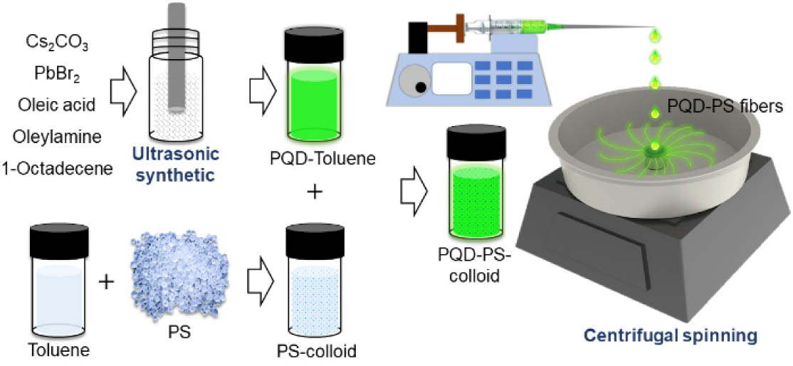
Figure 1.Schematic diagram of PQD-PS fiber centrifugal spinning.
C. Fabrication of PQD Fibers by Centrifugal Spinning
The PQD fibers were fabricated by centrifugal spinning. First, 3 g PS granules were dissolved in 5 mL of toluene. Afterward, the PS granules were completely dissolved in toluene, and the PQDs were mixed with PS through magnetic stirring until they were uniformly dissolved in toluene and transformed into colloids. Then, a high-speed rotary coater (Jiangsu LEBO Science, EZ4) was used to provide high-speed rotation. A quartz glass wafer (Jiangsu Zhuoyue Chemical, 2 mm) with a thickness of 2 mm and diameter of 20 mm was stuck to the top of the rotation shaft by vacuum absorption. The rotation speed was set to 7000 r/min. The PQD-PS colloid is extracted by an injector. The injector is a 1 mL medical injector with an elongated needle. After extracting an appropriate amount of PQD-PS colloid, it is placed on the syringe pump (Baoding Shenchen Pump Industry, SPLab04) for uniform injection during centrifugal spinning. The whole experiment setup of centrifugal spinning is shown in Fig. 1.
As the glass wafer began to spin, the PQD-PS colloid was deposited on the wafer dropwise at a uniform speed through a syringe pump. The colloid drops were dragged by centrifugal force, and, as the toluene was volatilized, the colloid drops transformed into fibers. The fibers are not formed on the surface of the wafer. They are formed at the edge of the wafer. For a better description of the centrifugal spinning process, a high-speed dynamic recorder (Fastec, HiSpec DVR 2F) is used for recording the spinning process. As shown in Fig. 2(a), the PQD-PS-colloid drops come out of the injector and drip onto the center of the wafer surface, which is spinning at high speed. Then, the colloid drops diffuse from the inside to the edge of the wafer. Driven by centrifugal force, the colloid drops are deformed and elongated. As the solvent evaporated, the liquid colloids finally transform into solid fibers. After spinning, the fibers are grown at the edge of the wafer as shown in Figs. 2(b) and 2(c), which can be easily collected.
![]()
Figure 2.(a) Centrifugal spinning process. PQD-PS fibers under (b) visible light and (c) UV light.
D. Measurement and Characterization
The crystal structure of the prepared PQDs was characterized by transmission electron microscopy (JEM-2100F, JEOL) at 200 kV. The morphology of the PQD-PS fibers was characterized by scanning electron microscopy (SEM, Hitachi, S-3700N). X-ray diffraction (XRD) analysis was conducted by a multiposition automatic X-ray diffractometer (PANalytical, X’pert Powder). Images of the single PQD fibers were recorded by a digital microscope (KEYENCE, VHX6000). The photoluminescence quantum yield (PLQY) was measured by an absolute PLQY spectrometer at an excitation wavelength of 365 nm (K.K. C9920, Hamamatsu Photonics and FLS10000, Edinburgh Instruments). Time-resolved fluorescence spectra were obtained by a Hamamatsu photoluminescence (PL) lifetime measuring instrument (Quantaurus-Tau C11367-11) at an excitation wavelength of 465 nm. The optical spectrum was obtained by a high-accuracy array spectroradiometer (EVERFINE, HAAS-2000) and an LED test source (EVERFINE, LTS-300). The absorption spectrum and emission spectrum were measured by a fluorophotometer (Shimadzu, RF-6000) and spectrophotometer (PERSEE, TU-1901), respectively. Details about the photoluminescence (PL) measurement are shown in Fig. 3; before the stability test, the fibers underwent a simple mechanical treatment to facilitate subsequent PL measurements. The fibers obtained from centrifugal spinning were pressed into a fiber membrane with a thickness of 0.1 to 0.5 mm. The fiber membrane was then cut into small fiber pieces for different environmental stability test, as shown in Fig. 3(b). The stability tests were carried out on the same sample at different times, so the thickness of the material known as the fiber piece was the same.
![]()
Figure 3.(a) Mechanical treatment before PL measurement. (b) Centrifugal spinning fibers and fiber pieces under visible light and UV light. (c) PL measurement setup.
During the PL measurement, the fiber pieces were placed between two wafers, as shown in Fig. 3(a). The PL measurement setup is shown in Fig. 3(c); the test sample is excited by exciting light, and the emitting light is for detection. A stationary fixture is used for the PL measurement. The fiber piece was placed in the center of the stationary fixture, and the measurement was conducted on the marking side of the fiber piece, making sure the probed location is consistent in continuous PL measurements. Besides, each PL measurement in stability tests is run multiple times to keep the error within an acceptable range (peak width and peak height are basically the same).
The modulations of the bandwidths of the QDs and yttrium aluminum garnet (YAG) films were measured by a simple VLC system, as shown in Fig. 4. The transmitter of the VLC system included an arbitrary signal generator (AFG, SIGLENT, SDG 6052X-E), a power amplifier (PA, mini circuits, ZHL-6A-S+), a direct-current power supply (DC, Keithley, 2231A), and a bias tee (mini circuit, ZFBT-4R2GW+). The AFG was used to generate a sinusoidal radio frequency (RF) signal, and the bias tee was used to couple the DC bias and RF signal to drive the 450 nm laser diode (LD, YuLiGuangZhou, 450 nm, 15 W). The electric signal was then transformed into a modulated optical signal. A divergent lens and a convex lens were used to scatter and collimate the blue light from the LD. Then, the collimated light excited the fluorescent fibers and films to generate white light. At the receiver, a convex lens as used to gather the modulated white light from the transmitter. An avalanche photodiode (APD, Meno System APD210) was used to convert the white light signal into electrical signals and amplify them. Then, the output of the APD was transmitted to an oscilloscope (OSC, SIGLENT, SDS 2000X Plus), which recorded the signals for analysis.
![]()
Figure 4.Experimental setup of the visible light communication system.
3. RESULTS AND DISCUSSION
The TEM image shown in Fig. 5(a) suggests that the nanocrystals are dispersed well in toluene and most of them are in cubic phase. As shown in Fig. 5(b), the selected area electron diffraction (SAED) pattern shows three ring patterns indexed to (002), (212), and (202) planes, which correspond to the diffraction peaks at 30.38°, 34.47°, and 43.69° in the XRD patterns of PQD-PS fibers [Fig. 6(b)]. The SAED pattern reveals polycrystalline diffraction feature from , suggesting a well-defined crystalline structure. The fast Fourier transformation (FFT) image in Fig. 5(c) also shows cubic and rectangular shapes of the crystal. The high-resolution TEM (HRTEM) image shown in Fig. 5(c) further reveals lattice spacings of 0.58 nm, which is in good agreement with the (100) lattice spacing of cubic [12,38,39]. A microscope image of a single PQD-PS fiber is shown in the inset of Fig. 6(c). The PQDs are covered by PS fibers, as shown in the image of fibers under ultraviolet light because they are well protected during water immersion. Figure 6(a) shows the SEM image of the PQDs-PS fibers. The average diameter of the fabricated fibers is approximately 3–5 μm. The X-ray diffraction patterns of PS fibers and PQD-PS fibers are shown in Fig. 6(b). The broad diffraction peaks can be ascribed to the amorphous PS fibers, and the detected main peaks at 21.5°, 26.4°, 28.6°, 30.4°, 34.5° and 43.7° correspond to the characteristic peaks of (PDF Card No. 18-0346), confirming the presence of PQDs within the PS fibers. However, except for the peaks of , the PQD-PS fibers show extra peaks at 22.58°, 25.55°, 27.75°, and 28.81°. These peaks correspond to (JCPDS 54-0750) and will be analyzed in the following discussion. The time-resolved fluorescence measurement of the PQDs is shown in Fig. 6(c). The measured PL decay kinetics is fitted with a double exponential function of time ():
![]()
Figure 5.Structural analyses of
![]()
Figure 6.(a) SEM image of PQD fibers. (b) XRD patterns of PS and PQD-PS fibers. (c) Time-resolved fluorescence measurement of the PQD-PS fibers (inset: single PQD fiber under ambient light and UV light). (d) Absorption and emission spectra of PQD-PS fibers.
The and are 8.81 and 35.69 ns, respectively, and the of the PQD-PS fibers is about 14.43 ns. In this work, the fluorescence lifetime is determined by the delay time of excitons produced by electron hole recombination. The and represent the time of photons passing through the first and second channels, respectively. The photons in the first channel conduct a direct recombination, while the photons in the second pass through the defect layer before recombination. That is why the is generally smaller, and the is larger [40,41]. Further, the fluorescence lifetime can be affected by many factors such as defect density of the materials and particle size and state.
Previous work has pointed out that the PQDs showed a double exponential PL decay in liquid state [21]. When it turns into a solid state, defects grow because of the loss of the ligand at the surface of the PQDs as the solvent evaporates. As the defects grow during centrifugal spinning, they increase the recombination time of the PQDs, which corresponds to the larger in this work. Details about defect growth of the PQD-PS fibers will be stressed in the following discussion.
The absorption and emission spectra of PQD-PS fibers are shown in Fig. 6(d). The PQD-PS fibers show a notable absorption peak at 314 nm, which is the characteristic absorption peak of NCs and will be explained in the following discussion. The emission peak of the PQD-PS fibers is centered at 517 nm, which is similar to that in a previous study [21].
The time-dependent emission spectra of the PQD-PS fibers exposed to air are shown in Fig. 7(a). During the first two days, the emission intensity of the PQDs decreased by 25%. The fast decline in the PL intensity in the first two days can be explained by the centrifugal spinning method. Because the PQD-PS colloid used in centrifugal spinning is prepared in advance, part of the QDs are inevitably exposed and absorbed to the fiber surface during centrifugal spinning. QDs are sensitive to moisture and oxygen, which destroy PQD crystals. The PL intensity of the PQDs decreased by 25% in the first two days, which can be attributed to the degradation of the PQDs at the fiber surface, which is directly exposed to air. As the degradation of the PQDs occurred at the fiber surface, the decomposition products of the degradation process were also absorbed on the surface. These decomposition products will further reduce the light emission efficiency. The PQDs inside the fibers are protected from aging by environmental factors, corresponding to an almost unchanged emission intensity after two days. After exposure to air for one week, the PQD-PS fibers still maintained 75% of their emission intensity, showing little redshift and emission attenuation. The time-dependent emission spectra of the PQD-PS fibers immersed in water are shown in Figs. 7(b) and 6(c). The PQD-PS fibers show a notable redshift during the first two days. However, the emission intensity of the PQD-PS fibers demonstrates an increase of 66%, as shown in Fig. 7(d). After immersion in water for one week, the emission intensity of the PQD-PS fibers decreased by 30% compared with that on the second day but was still 16% higher than that on the first day. The redshift basically disappeared after the second day. The XRD patterns of the PQD-PS fibers exposed to moisture for one week, air (as well as indoor light) for a week, and UV light for three days are shown in Figs. 8(a)–8(c), respectively. After exposure to moisture for one week, air for one week, and UV light for three days, the PQD-PS fibers still showed notable peaks corresponding to the original measurement, confirming the stability of the crystalline structure of the PQDs in the PS fibers. The XRD patterns of the air group and UV light group show a slight declining peak, which corresponds to their stability. However, the XRD pattern of the water group shows an increasing peak. The strengthened XRD peaks, increased PL intensity, and notable PL redshift of the fibers in the water group are unusual.
![]()
Figure 7.Emission spectra of PQD-PS fibers after (a) exposure to air and (b) immersion in water for one week. (c) Emission spectra of PQD-PS fibers after immersion in water for 11 months (inset: fibers soaking in water for 11 months under UV light). (d) PL intensity of fibers after stability test. (e) PL peak wavelength trend of PQD-PS fibers during water immersion. (f) PL decay curves of PQD-PS fibers after immersion in water and exposure to air.
![]()
Figure 8.XRD patterns of PQD-PS fibers after (a) immersion in water, (b) exposure to air, and (c) exposure to UV light.
![]()
Figure 9.PQD-PS fibers soaking in hexane under (a) visible light and (b) UV light. PQD-PS fibers after soaking in hexane and ultrasonic treatment under (c) visible light and (d) UV light. Hexane (right) and hexane after ultrasonic treatment (left) under (e) visible light and (f) UV light.
To further verify the distribution of the PQDs in the PS fibers, a more visual experiment is conducted. A small bunch of PQD-PS fibers was soaked in a reagent bottle with 10 mL hexane, as shown in the Figs. 9(a) and 9(b). The reagent bottle with PQD-PS fibers then performed an ultrasonic treatment for 5 min, ensuring that the component at the surface of the fiber is fully peeled off or dissolved into hexane. Figures 9(e) and 9(f) show the hexane before and after PQD-PS fiber soaking (F-hexane). The F-hexane shows little fluorescence after the PQD-PS fiber soak. The absorption and emission spectra of F-hexane and hexane were measured by a fluorophotometer (Shimadzu, RF-6000) and a spectrophotometer (Persee, TU-1901), respectively. However, the fluorescence of F-hexane is too low to be detected, leading to zero intensity of the absorption and emission spectra, as with the nonfluorescent hexane. Figures 9(c) and 9(d) show the PQD-PS fibers after soaking in hexane and ultrasonic treatment, which still have fluorescence properties, suggesting protection of the PQDs. The experiments above indicated that a small amount of PQDs are distributed at the surface of the fibers, which is inevitable in centrifugal spinning. However, most of the PQDs can be covered and well protected by the PS fibers, which corresponds to XRD, PL, and PLQY measurements.
As we knew, moisture is harmful to PQDs [38,42,43]. In this work, we used hydrophobic PS for PQD packaging. Our work shows that the PQD-PS fibers show an increase in PL intensity in the moisture stability test, as shown in Fig. 7(d). In fact, studies have shown that water in certain situations can improve the performance of QDs [44–46]. As the XRD patterns show in Fig. 8(a), except for the peaks of , the PQD-PS fibers show extra peaks at 22.58°, 25.55°, 27.75°, and 28.81°. These peaks correspond to (JCPDS 54-0750). Considering the notable absorption peak at 314 nm of the PQD-PS fiber absorption spectra and XRD patterns, we can confirm the existence of [47]. We believe Cs4PbBr4 is at the outside of the PQD-PS fibers. The formation might occur on the surface of the fibers during rapid solvent evaporation because the small amount of residual nonvolatile oleylamine would trigger the process [48]. After immersion in water, the characteristic peaks of disappeared or weakened, as shown by the blue XRD pattern in Fig. 8(a), while the characteristic peaks of strengthened. This can be explained by the transformation into and CsBr on the surface of the fibers while contacting the water [47]. Furthermore, PQDs obtained by this water-triggered transformation present excellent stability against moisture, which might be attributed to surface passivation.
After discussing the above, we conclude that the increase in emission intensity is the combined effect of the transformation from to and surface defect dissolution. Because is nonluminous, the transformation from to luminous and the water-assented surface passivation of the PQDs on the fiber surface contribute to the PL increase in the fibers during the first two days after immersion in water. As the surface perovskite continues to dissolve in water, the decrease in the PL intensity corresponding to the decrease in the PL intensity of the water group after a short time increases, as shown in Fig. 7(d). Nevertheless, there was notable PL intensity increase after long-term water immersion, which could be explained by the enhancement in the light-out efficiency. During the centrifugal spinning process, part of the PQDs are absorbed on the surface of the fibers. These PQDs are directly exposed to air and light, and some of them are destroyed, forming nonluminous decomposition products. These nonluminous ingredients and are absorbed on the surface of the fibers as defect layers, which directly reduces the light emission efficiency of the fibers in the first PL measurement. As shown in Fig. 7(f), the double exponential PL decay of the PQD-PS fibers can be explained by the longer recombination time of the quantum dots caused by the surface defects that formed during spinning. After immersion in water for one week, the fluorescence lifetime of the PQD-PS fibers decreased, and the PL decay curve was closer to a single-exponential fitting. The PL decay decline is attributed to the dissolution of the defects and corresponds to a previous study [48].
The PL intensity peak of the PQD-PS fibers redshifted from 517 to 530 nm, accounting for a total redshift of 13 nm, as shown in Fig. 7(e). As the PL measurement in Fig. 7(a) shows, the redshift only occurred in the water-immersion group. Moisture-assisted crystal growth has previously been confirmed in various crystal systems, including [44,45,49]. We believe that moisture is the main cause of the redshift in the PQD-PS fibers. As the PL measurement shows in Fig. 7(b), the PQD-PS fibers are absolutely contained in the PS fibers because there is no notable perovskite hydrolysis during water immersion. The immersion of PQD-PS fibers in water might result in a small amount of moisture permeation within grain boundaries, inducing grain boundary creep and subsequently merging adjacent grains together [45]. The XRD pattern of the PQD-PS fibers in Fig. 8(a) shows the sharper diffraction peaks (the main peaks of JCPDS 18-0364) of , which confirms the improved crystallinity of the perovskite structure in PQD-PS fibers after water immersion and corresponds to Refs. [44,45].
The PL peak wavelength trend of the PQD-PS fibers is shown in Fig. 7(e). Through the PL peak wavelength trend, we can further understand the moisture erosion process. The PL peak shows a slight redshift during the first 10 h, which means that crystal growth did not start at this point. One reasonable explanation for this is that the transformation from to and the surface defect dissolution on the fiber surface slow moisture erosion. From 10 to 24 h, the PQD-PS fibers exhibit a notable redshift and then tend to be stable after 48 h, suggesting that the crystal growth of the PQDs continues for 10 to 20 h. The above trend suggests that the growth of was not completed, even in the PS colloid, and could be triggered in certain conditions, such as moisture. There might be small account of moisture in the PQD-PS fibers due to some gaps, which would facilitate the crystal growth of PQDs and lead to a redshift. However, the immersed moisture did not destroy the PQDs, suggesting the effectiveness of the centrifugal spinning strategy and ability to protect PQDs from water, even after 11 months of water immersion. This growth of crystals directly caused the redshift, and we are doing further research on the mechanism of crystal growth. We believe this growth will be suppressed or eliminated by adopting a better method of crystal synthesis.
As discussed, inhibiting the formation of on the surface of PQD-PS fibers can fundamentally reduce the change of PL intensity on the fiber surface. The to transformation depends on the concentration of bromide ion and oleylamine [47,48]. Thus, the transformation process can be suppressed by optimizing the concentration of the original compound of PQDs synthesis. In addition, the QDs inevitably remaining at the fiber surface during centrifugal spinning can be removed by water or hexane washing before application, which can further guarantee their stability.
To further reveal the luminescent characterization of the PQD-PS fibers, the PLQY measurements of fibers in different stability tests are conducted as shown in Table 1. Please note that the five-month stability test is conducted by the same bunch of PQD-PS fibers and the 17 months stability test is conducted by another bunch of PQD-PS fibers. PLQY Stability of PQD-PS FibersStability Test 7 Days 2 Weeks 5 Months Exposure to air 45.1% 43.5% 15.6% Immersion in water 54.9% 44.4% 44.4%
The PLQYs of the fresh fibers and the fibers after exposure to air and immersion in water for one week were 53.7%, 45.1%, and 54.9%, respectively. The increasing PLQY of PQD-PS fibers after water immersion corresponds to the surface change discussed above. The PLQYs of the PQD-PS fibers after immersion in water and exposure to air for two weeks are 43.5% and 44.4%, respectively. After immersion in water and exposure to air for five months, the PLQY declined to 15.6% and 44.4%, respectively. We reviewed the PLQY stability of with different composites in other works, as shown in Table 2. According to the stability performance of the at composites in Table 2, the centrifugal spinning PQD-PS fibers maintain 81% and 83% relative PLQY after exposure to air for two weeks and immersion in water for five months, respectively, suggesting considerable stability performance both in air and water. Moreover, the first bunch of PQD-PS fibers still holds 44% of PLQY after 17 months water immersion, which shows remarkable stability in hostile environments. PLQY Stability of CsPbBr3 with Different CompositesPOSS 62% 98% (water, 2.5 months) [ TDPA 68% [ PMMA 45% 75% (humidity, 3 days) [ EC 37.2% 87% (air, 6 days) [ SBS 23% [ PS 48% 70% (water, 8 days) [ EVA 40.5% [ PS 44% 82% (water, 24 h) [ PS 23.3% 83% (water, 3 months) [ S-AIM 75.6% 51% (water, 3.5 months) [ SR/PVP 24% 85% (moist air, 5 days) [ This work 53.7% 81% (air, 2 weeks) 83% (water, 5 months)
Still, there is a notable PL increasement after 11 months water immersion, which might be explained by the enhancement of light-out efficiency of the fibers. During the centrifugal spinning process, part of the PQDs are absorbed at the fiber surface. These PQDs are directly exposed to the air and light, and part of them are destroyed into nonluminous decomposition products. These nonluminous ingredients and the are absorbed on the fiber surface as defect layers, which directly reduce the light emission efficiency of the fibers in the first PL measurement. Therefore, the PL intensity of the PQD-PS fibers obtained in the first measurement is extremely likely to be underestimated. Furthermore, the PLQY of the PQD-PS fibers can better describe the fluorescence characteristic change during the water stability test. The original PLQY of the PQD-PS fibers is 53.7%. After one week water immersion, the PLQY increases to 54.9%, which corresponds to the surface change of the fibers, as discussed in the paper. After two weeks’ water immersion, the PLQY declines to 44.4% and maintains a high level after five months’ water immersion, which corresponds to the completed dissolution of the fluorescent substance at the fiber surface. We can conclude that the 44.4% PLQY is derived entirely from the quantum dots within the fibers. Moreover, the first bunch of PQD-PS fibers still holds 44% of PLQY after 17 months water immersion, which also confirms the above discussion about the surface dissolution.
Inorganic PQDs are favored in display and illumination applications due to their remarkable optoelectronic performance. Here, we prepared a QD-based white LED (WLED) with PQD-PS fibers. A CdSe/ZnS QD polydimethylsiloxane (PDMS) film and a commercial blue LED were used to generate white light, as shown in the inset in Fig. 10(a). The electroluminescence (EL) spectrum and the CIE color gamut of the QD-based WLED are shown in Figs. 10(a) and 10(b). The white light EL spectrum generated by the QD-based WLED consists of three emission peaks located at 450, 520, and 625 nm, corresponding to a blue LED, PQD-PS fibers, and the CdSe/ZnS QD PDMS film, respectively. The fabricated QD-based WLED showed a correlated color temperature (CCT) of 6897 K and CIE coordinates of (0.33,0.32) at a driving current of 350 mA. Compared with the common standard, the QD-based WLED has a wide color gamut, with 128% of the NTSC and 95% of Rec. 2020. Considering their environmental stability, the PQD-PS fibers show great outdoor display application potential.
![]()
Figure 10.(a) EL spectrum of QD-based white LEDs. (b) Color coordinates and color gamut of QD-based white LEDs plotted on the CIE1931 chromaticity diagram. (c) Frequency response of the LD, LD + YAG white light, LD + PQD-PS fibers, LD + CdSe/ZnS PDMS film, and LD + PQD-PS + CdSe/ZnS white light. (d) The
Compared with the conventional white light system, the PQDs have a much shorter PL lifetime (nanosecond) than the YAG phosphor (microsecond). The bandwidth of the PQD-PS fibers can be estimated by Eq. (3) [59]:
According to the PL lifetime obtained above, the bandwidth estimation of the PQD-PS fibers is 11 MHz. A simplified white light/visible light communication system was built to evaluate the communication performance of PQD-PS fibers. As shown in Fig. 10(c), the bandwidths of LD, LD + CdSe/ZnS, LD + PQD-PS fibers, and LD + CdSe/ZnS + PQD-PS fibers are ,, , and , respectively. The bandwidth of the LD + CdSe/ZnS PDMS film is , corresponding to the previous study [37]. The bandwidth of the LD + PQD-PS fibers is , which is similar to the estimated bandwidth of 11 MHz. The bandwidth of the LD + CdSe/ZnS + PQD-PS fibers is and is located at the middle of the bandwidths of two components, suggesting the bandwidth is contributed by the CdSe/ZnS and PQD-PS fibers. The measurement of the PQD-PS fibers corresponds to the estimation. Figure 10(d) shows the time-dependent bandwidth measurement of the PQD-PS fibers. The bandwidth of the PQD-PS fibers exhibited little attenuation after exposure to the natural environment, showing promising stability in communication applications.
4. CONCLUSIONS
In this work, we used a facile centrifugal spinning method to fabricate perovskite quantum-dot fibers. The fabricated PQD-PS fibers maintained 44% and 43.5% PLQY after immersion in water for 17 months and exposure to air for two weeks, respectively, exhibiting considerable environmental stability. The water-stability mechanism of the fibers can be explained by the changing defect density, crystal growth of PQDs, and the molecular transformation at the fiber surface. Considering the remarkable photoelectric performance of PQDs, a WLED was manufactured by the PQD-PS fibers. The WLED shows satisfying performance, with a wide color gamut (128% of NTSC and 95% of Rec. 2020), a CCT of 6897 K, and CIE coordinates of (0.33,0.32). Furthermore, a white light/visible light communication system was built based on the PQD-PS fibers. The PQD-PS fibers with the CdSe/ZnS QD white light system present a bandwidth of 11.2 MHz, which is much higher than that of the conventional YAG white light system. After exposure to air for one week, the bandwidth of the PQD-PS fibers exhibited no attenuation. The environmental stability and considerable performance of PQD-PS fibers show great potential in dual display and communication applications.
Acknowledgment
Acknowledgment. The authors would like to acknowledge Guangdong University Students Special Funds for scientific and technological innovation cultivation and also acknowledge Cunjiang Song, Guanwei Liang, Yaoxing Song, Kejian Wu, Yongjun Chen, Jiexin Li, Longshi Rao, and Changkun Shao from South China University of Technology and Jieyuan Wang from Shaanxi Normal University for experimental guidance and help, Peisheng Chen from Guangdong Ocean University for image rendering, and good care from Miss Yaqin.
References
[1] L. Protesescu, S. Yakunin, M. I. Bodnarchuk, F. Krieg, R. Caputo, C. H. Hendon, R. X. Yang, A. Walsh, M. V. Kovalenko. Nanocrystals of cesium lead halide perovskites (CsPbX3, X = Cl, Br, and I): novel optoelectronic materials showing bright emission with wide color gamut. Nano Lett., 15, 3692-3696(2015).
[2] M. V. Kovalenko, L. Protesescu, M. I. Bodnarchuk. Properties and potential optoelectronic applications of lead halide perovskite nanocrystals. Science, 358, 745-750(2017).
[3] X. Gong, M. Li, X. B. Shi, H. Ma, Z. K. Wang, L. S. Liao. Controllable perovskite crystallization by water additive for high-performance solar cells. Adv. Funct. Mater., 25, 6671-6678(2015).
[4] J. Z. Song, J. H. Li, X. M. Li, L. M. Xu, Y. H. Dong, H. B. Zeng. Quantum dot light-emitting diodes based on inorganic perovskite cesium lead halides (CsPbX3). Adv. Mater., 27, 7162-7167(2015).
[5] Z. T. Li, K. Cao, J. S. Li, X. W. Du, Y. Tang, B. H. Yu. Modification of interface between PEDOT:PSS and perovskite film inserting an ultrathin LiF layer for enhancing efficiency of perovskite light-emitting diodes. Org. Electron., 81, 105675(2020).
[6] H. M. Zhu, Y. P. Fu, F. Meng, X. X. Wu, Z. Z. Gong, Q. Ding, M. V. Gustafsson, M. T. Trinh, S. Jin, X. Y. Zhu. Lead halide perovskite nanowire lasers with low lasing thresholds and high quality factors. Nat. Mater., 14, 636-642(2015).
[7] S. F. Leung, K. T. Ho, P. K. Kung, V. K. S. Hsiao, H. N. Alshareef, Z. L. Wang, J. H. He. A self-powered and flexible organometallic halide perovskite photodetector with very high detectivity. Adv. Mater., 30, 1704611(2018).
[8] R. H. Liu, J. Q. Zhang, H. Zhou, Z. H. Song, Z. N. Song, C. R. Grice, D. J. Wu, L. P. Shen, H. Wang. Solution-processed high-quality cesium lead bromine perovskite photodetectors with high detectivity for application in visible light communication. Adv. Opt. Mater., 8, 1901735(2020).
[9] N. Strobel, N. Droseros, W. Kontges, M. Seiberlich, M. Pietsch, S. Schlisske, F. Lindheimer, R. R. Schroder, U. Lemmer, M. Pfannmoller, N. Banerji, G. Hernandez-Sosa. Color-selective printed organic photodiodes for filterless multichannel visible light communication. Adv. Mater., 32, 1908258(2020).
[10] W. H. Li, S. B. Li, L. Duan, H. J. Chen, L. D. Wang, G. F. Dong, Z. Y. Xu. Squarylium and rubrene based filterless narrowband photodetectors for an all-organic two-channel visible light communication system. Org. Electron., 37, 346-351(2016).
[11] E. Lopez-Fraguas, B. Arredondo, C. Vega-Colado, G. del Pozo, M. Najafi, D. Martin-Martin, Y. Galagan, J. M. Sanchez-Pena, R. Vergaz, B. Romero. Visible light communication system using an organic emitter and a perovskite photodetector. Org. Electron., 73, 292-298(2019).
[12] Y. Tong, E. Bladt, M. F. Ayguler, A. Manzi, K. Z. Milowska, V. A. Hintermayr, P. Docampo, S. Bals, A. S. Urban, L. Polavarapu, J. Feldmann. Highly luminescent cesium lead halide perovskite nanocrystals with tunable composition and thickness by ultrasonication. Angew. Chem., 55, 13887-13892(2016).
[13] S. L. Mei, X. Y. Liu, W. L. Zhang, R. Liu, L. R. Zheng, R. Q. Guo, P. F. Tian. High-bandwidth white-light system combining a micro-LED with perovskite quantum dots for visible light communication. ACS Appl. Mater. Interfaces, 10, 5641-5648(2018).
[14] S. Jung, J. H. Kim, J. W. Choi, J. W. Kang, S. H. Jin, Y. Kang, M. Song. Enhancement of photoluminescence quantum yield and stability in CsPbBr3 perovskite quantum dots by trivalent doping. Nanomaterials, 10, 710(2020).
[15] S. L. Mei, B. B. Yang, X. Wei, H. Q. Dai, Z. H. Chen, Z. J. Cui, G. L. Zhang, F. X. Xie, W. L. Zhang, R. Q. Guo. Facile synthesis and optical properties of CsPbX3/ZIF-8 composites for wide-color-gamut display. Nanomaterials, 9, 832(2019).
[16] Z. T. Li, X. T. Tang, J. D. Yu, Y. Tang, B. H. Yu, Y. L. Hu, B. Liu, X. R. Ding. Lifetime enhancement of a circulated cooling perovskite quantum dots colloidal solution system for laser illuminations. IEEE Access, 7, 136214-136222(2019).
[17] I. Dursun, C. Shen, M. R. Parida, J. Pan, S. P. Sarmah, D. Priante, N. Alyami, J. Liu, M. I. Saidaminov, M. S. Alias, A. L. Abdelhady, T. K. Ng, O. F. Mohammed, B. S. Ooi, O. M. Bakr. Perovskite nanocrystals as a color converter for visible light communication. ACS Photon., 3, 1150-1156(2016).
[18] C. H. Lin, C. Y. Kang, A. Verma, T. Z. Wu, Y. M. Pai, T. Y. Chen, C. L. Tsai, Y. Z. Yang, S. K. Sharma, C. W. Sher, Z. Chen, P. T. Lee, S. R. Chung, H. C. Kuo. Ultrawide color gamut perovskite and CdSe/ZnS quantum-dots-based white light-emitting diode with high luminous efficiency. Nanomaterials, 9, 1314(2019).
[19] H. Huang, M. I. Bodnarchuk, S. V. Kershaw, M. V. Kovalenko, A. L. Rogach. Lead halide perovskite nanocrystals in the research spotlight: stability and defect tolerance. ACS Energy Lett., 2, 2071-2083(2017).
[20] B. Hailegnaw, S. Kirmayer, E. Edri, G. Hodes, D. Cahen. Rain on methylammonium lead iodide based perovskites: possible environmental effects of perovskite solar cells. J. Phys. Chem. Lett., 6, 1543-1547(2015).
[21] Z. T. Li, C. J. Song, J. S. Li, G. W. Liang, L. S. Rao, S. D. Yu, X. R. Ding, Y. Tang, B. H. Yu, J. Z. Ou, U. Lemmer, G. Gomard. Highly efficient and water-stable lead halide perovskite quantum dots using superhydrophobic aerogel inorganic matrix for white light-emitting diodes. Adv. Mater. Technol., 5, 1900941(2020).
[22] J. S. Li, Y. Tang, Z. T. Li, X. R. Ding, B. H. Yu, L. W. Lin. Largely enhancing luminous efficacy, color-conversion efficiency, and stability for quantum-dot white LEDs using the two-dimensional hexagonal pore structure of SBA-15 mesoporous particles. ACS Appl. Mater. Interfaces, 11, 18808-18816(2019).
[23] Y. T. J.-S. Li, Z.-T. Li, J.-X. Li, X.-R. Ding, B.-H. Yu, S.-D. Yu, J.-Z. Ou, H.-C. Kuo. Toward 200 lumens per watt of quantum-dot white-light-emitting diodes by reducing reabsorption loss. ACS Nano, 15, 550-562(2021).
[24] Y. Wei, X. R. Deng, Z. X. Xie, X. C. Cai, S. S. Liang, P. Ma, Z. Y. Hou, Z. Y. Cheng, J. Lin. Enhancing the stability of perovskite quantum dots by encapsulation in crosslinked polystyrene beads via a swelling-shrinking strategy toward superior water resistance. Adv. Funct. Mater., 27, 1703535(2017).
[25] P. G. Papagiorgis, A. Manoli, A. Alexiou, P. Karacosta, X. Karagiorgis, G. Papaparaskeva, C. Bernasconi, M. I. Bodnarchuk, M. V. Kovalenko, T. Krasia-Christoforou, G. Itskos. Robust hydrophobic and hydrophilic polymer fibers sensitized by inorganic and hybrid lead halide perovskite nanocrystal emitters. Front. Chem., 7, 87(2019).
[26] L. H. Meng, C. G. Yang, J. J. Meng, Y. Z. Wang, Y. Ge, Z. Q. Shao, G. F. Zhang, A. L. Rogach, H. Z. Zhong.
[27] H. Liao, S. B. Guo, S. Cao, L. Wang, F. M. Gao, Z. B. Yang, J. J. Zheng, W. Y. Yang. A general strategy for
[28] H. H. Zhang, D. F. Fu, Z. T. Du, H. Fu, G. Shao, W. Y. Yang, J. J. Zheng.
[29] D. H. Jiang, S. Kobayashi, C. C. Jao, Y. Mato, T. Isono, Y. H. Fang, C. C. Lin, T. Satoh, S. H. Tung, C. C. Kuo. Light down-converter based on luminescent nanofibers from the blending of conjugated rod-coil block copolymers and perovskite through electrospinning. Polymers, 12, 84(2020).
[30] X. Lu, Y. Hu, J. Z. Guo, C. F. Wang, S. Chen. Fiber-spinning-chemistry method toward
[31] T. T. Cui, Z. J. Zhu, R. Cheng, Y. L. Tong, G. Peng, C. F. Wang, S. Chen. Facile access to wearable device via microfluidic spinning of robust and aligned fluorescent microfibers. ACS Appl. Mater. Interfaces, 10, 30785-30793(2018).
[32] L. Y. Ron, S. P. Kotha. Centrifugal jet spinning for highly efficient and large-scale fabrication of barium titanate nanofibers. Mater. Lett., 117, 153-157(2014).
[33] L. K. Hromadko, E. Koudelkova, R. Bulanek, J. M. Macak. SiO2 fibers by centrifugal spinning with excellent textural properties and water adsorption performance. ACS Omega, 2, 5052-5059(2017).
[34] M. R. Badrossamay, H. A. McIlwee, J. A. Goss, K. K. Parker. Nanofiber assembly by rotary jet-spinning. Nano Lett., 10, 2257-2261(2010).
[35] A. Barhoum, K. Pal, H. Rahier, H. Uludag, I. S. Kim, M. Bechelany. Nanofibers as new-generation materials: from spinning and nano-spinning fabrication techniques to emerging applications. Appl. Mater. Today, 17, 1-35(2019).
[36] E. Ercan, P.-C. Tsai, J.-Y. Chen, J.-Y. Lam, L.-C. Hsu, C.-C. Chueh, W.-C. Chen. Stretchable and ambient stable perovskite/polymer luminous hybrid nanofibers of multicolor fiber mats and their white LED applications. ACS Appl. Mater. Interfaces, 11, 23605-23615(2019).
[37] B. H. L. Yu, S. Liang, X. Ding, Z. Li, Y. Tang. A sandwich structure light-trapping fluorescence antenna with large field of view for visible light communication. IEEE Trans. Electron Dev., 68, 565-571(2021).
[38] A. Loiudice, S. Saris, E. Oveisi, D. T. L. Alexander, R. Buonsanti. CsPbBr3 QD/AlO
[39] L. S. Rao, Y. Tang, C. J. Song, K. Xu, E. T. Vickers, S. B. Naghadeh, X. R. Ding, Z. T. Li, J. Z. Zhang. Polar-solvent-free synthesis of highly photoluminescent and stable CsPbBr3 nanocrystals with controlled shape and size by ultrasonication. Chem. Mater., 31, 365-375(2019).
[40] V. S. Chirvony, S. Gonzalez-Carrero, I. Suarez, R. E. Galian, M. Sessolo, H. J. Bolink, J. P. Martinez-Pastor, J. Perez-Prieto. Delayed luminescence in lead halide perovskite nanocrystals. J. Phys. Chem. C, 121, 13381-13390(2017).
[41] V. Malgras, J. Henzie, T. Takei, Y. Yamauchi. Stable blue luminescent CsPbBr3 perovskite nanocrystals confined in mesoporous thin films. Angew. Chem., 57, 8881-8885(2018).
[42] S. N. Raja, Y. Bekenstein, M. A. Koc, S. Fischer, D. Zhang, L. Lin, R. O. Ritchie, P. Yang, A. P. Alivisatos. Encapsulation of perovskite nanocrystals into macroscale polymer matrices: enhanced stability and polarization. ACS Appl. Mater. Interfaces, 8, 35523-35533(2016).
[43] Y. Wei, Z. Y. Cheng, J. Lin. An overview on enhancing the stability of lead halide perovskite quantum dots and their applications in phosphor-converted LEDs. Chem. Soc. Rev., 48, 310-350(2019).
[44] S. Huang, Z. Li, B. Wang, N. Zhu, C. Zhang, L. Kong, Q. Zhang, A. Shan, L. Li. Morphology evolution and degradation of CsPbBr3 nanocrystals under blue light-emitting diode illumination. ACS Appl. Mater. Interfaces, 9, 7249-7258(2017).
[45] J. B. You, Y. M. Yang, Z. R. Hong, T. B. Song, L. Meng, Y. S. Liu, C. Y. Jiang, H. P. Zhou, W. H. Chang, G. Li, Y. Yang. Moisture assisted perovskite film growth for high performance solar cells. Appl. Phys. Lett., 105, 183902(2014).
[46] Y. Liu, F. Li, Q. Liu, Z. Xia. Synergetic effect of postsynthetic water treatment on the enhanced photoluminescence and stability of CsPbX3 (X = Cl, Br, I) perovskite nanocrystals. Chem. Mater., 30, 6922-6929(2018).
[47] L. Wu, H. Hu, Y. Xu, S. Jiang, M. Chen, Q. Zhong, D. Yang, Q. Liu, Y. Zhao, B. Sun, Q. Zhang, Y. Yin. From nonluminescent Cs4PbX6 (X = Cl, Br, I) nanocrystals to highly luminescent CsPbX3 nanocrystals: water-triggered transformation through a CsX-stripping mechanism. Nano Lett., 17, 5799-5804(2017).
[48] Z. Liu, Y. Bekenstein, X. Ye, S. C. Nguyen, J. Swabeck, D. Zhang, S.-T. Lee, P. Yang, W. Ma, A. P. Alivisatos. Ligand mediated transformation of cesium lead bromide perovskite nanocrystals to lead depleted Cs4PbBr6 nanocrystals. J. Am. Chem. Soc., 139, 5309-5312(2017).
[49] Y. N. Chen, M. H. He, J. J. Peng, Y. Sun, Z. Q. Liang. Structure and growth control of organic-inorganic halide perovskites for optoelectronics: from polycrystalline films to single crystals. Adv. Sci., 3, 1500392(2016).
[50] H. Huang, B. K. Chen, Z. G. Wang, T. F. Hung, A. S. Susha, H. Z. Zhong, A. L. Rogach. Water resistant CsPbX3 nanocrystals coated with polyhedral oligomeric silsesquioxane and their use as solid state luminophores in all-perovskite white light-emitting devices. Chem. Sci., 7, 5699-5703(2016).
[51] T. T. Xuan, X. F. Yang, S. Q. Lou, J. J. Huang, Y. Liu, J. B. Yu, H. L. Li, K. L. Wong, C. X. Wang, J. Wang. Highly stable CsPbBr3 quantum dots coated with alkyl phosphate for white light-emitting diodes. Nanoscale, 9, 15286-15290(2017).
[52] K. Z. Ma, X. Y. Du, Y. W. Zhang, S. Chen.
[53] Y. H. Song, J. S. Yoo, B. K. Kang, S. H. Choi, E. K. Ji, H. S. Jung, D. H. Yoon. Long-term stable stacked CsPbBr3 quantum dot films for highly efficient white light generation in LEDs. Nanoscale, 8, 19523-19526(2016).
[54] C. C. Lin, D. H. Jiang, C. C. Kuo, C. J. Cho, Y. H. Tsai, T. Satoh, C. Su. Water-resistant efficient stretchable perovskite-embedded fiber membranes for light-emitting diodes. ACS Appl. Mater. Interfaces, 10, 2210-2215(2018).
[55] Y. Li, Y. Lv, Z. Q. Guo, L. B. Dong, J. H. Zheng, C. F. Chai, N. Chen, Y. J. Lu, C. Chen. One-step preparation of long-term stable and flexible CsPbBr3 perovskite quantum dots/ethylene vinyl acetate copolymer composite films for white light-emitting diodes. ACS Appl. Mater. Interfaces, 10, 15888-15894(2018).
[56] Y. C. Wong, J. D. Ng, Z. K. Tan. Perovskite-initiated photopolymerization for singly dispersed luminescent nanocomposites. Adv. Mater., 30, 1800774(2018).
[57] D. H. Jiang, Y. H. Tsai, L. Veeramuthu, F. C. Liang, L. C. Chen, C. C. Lin, T. Satoh, S. H. Tung, C. C. Kuo. Novel ultra-stable and highly luminescent white light-emitting diodes from perovskite quantum dots-polymer nanofibers through biaxial electrospinning. APL Mater., 7, 111105(2019).
[58] J. Hai, H. Li, Y. Zhao, F. J. Chen, Y. Peng, B. D. Wang. Designing of blue, green, and red CsPbX3 perovskitecodoped flexible films with water resistant property and elimination of anion-exchange for tunable white light emission. Chem. Commun., 53, 5400-5403(2017).
[59] Y. L. Zhang, M. J. Jiang, T. Han, X. T. Xiao, W. L. Chen, L. Wang, K. S. Wong, R. Wang, K. Wang, B. Z. Tang, K. S. Wu. Aggregation-induced emission luminogens as color converters for visible-light communication. ACS Appl. Mater. Interfaces, 10, 34418-34426(2018).
[60] S. Liang. Original optical data of PQD-PS fibers(2021).

Set citation alerts for the article
Please enter your email address
© Copyright 2018-2021 | Chinese Laser Press. All Rights Reserved 沪ICP备15018463号-20