
Lingqiang Meng, Pengyang Zhao, Fanchao Meng, Long Chen, Yong Xie, Yikun Wang, Wei Bian, Jianjun Jia, Tao Liu, Shougang Zhang, Jianyu Wang. Design and fabrication of a compact, high-performance interference-filter-based external-cavity diode laser for use in the China Space Station[J]. Chinese Optics Letters, 2022, 20(2): 021407
- Chinese Optics Letters
- Vol. 20, Issue 2, 021407 (2022)
Abstract
1. Introduction
The time measurement accuracy of a strontium optical lattice clock (SOLC) has entered the order of ,which is the highest performance index in the world[
ECDLs use selective feedback to achieve laser beams with narrow linewidth and tunability[
In the present work, a compact, high-performance IF-ECDL was developed. The optical and mechanical designs are demonstrated in detail. The IF-ECDL has no moving parts or spring-loaded structures, which guaranteed high reliability. Titanium and aluminum alloys were used to make structures of the IF-ECDL. Together with secondary temperature control, the IF-ECDLs have a good thermal design. Performances of the IF-ECDL were measured before and after aerospace environmental tests. Conditions of the aerospace environmental tests are also presented.
Sign up for Chinese Optics Letters TOC. Get the latest issue of Chinese Optics Letters delivered right to you!Sign up now
2. Development of the IF-ECDL
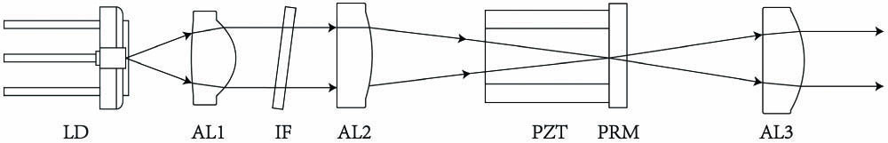
The optical schematic of the developed IF-ECDL is depicted in Fig. 1. The IF-ECDL is based on a cat’s eye configuration. An anti-reflection coated laser diode (LD), which has a wavelength of 695–707 nm, is used as the laser source. After emitting from the LD, laser beam is collimated by an aspherical lens (AL1) with a focus length of 4.02 mm. Then, an IF is used to select the longitude modes. By adjusting the laser beam incidence angle to the IF, a laser is selected to meet the requirement of the SOLC. The laser beam is then focused on a partially reflective mirror (PRM), which has a reflection of 30% and transmission of 70%, by a cat’s eye AL2 with a focus length of 15.29 mm to form an external cavity. In order to tune the laser frequency, the PRM is glued on a piezoelectric ceramic (PZT) to vary the length of the external cavity. Finally, the laser beam is collimated by AL3 with a focus length of 9.6 mm.
![]()
Figure 1.Optical schematic of the IF-ECDL. LD, laser diode; AL1, aspherical lens 1; IF, interference filter; AL2, aspherical lens 2; PZT, piezoelectric ceramic; PRM, partially reflective mirror; AL3, aspherical lens 3.
Figure 2 shows the external structure and cross-sectional three-dimensional (3D) view of the IF-ECDL. Considering the vibration and shock during rocket launch, the mechanical strength and reliability of the IF-ECDL should be guaranteed. Other than the protective shell (PS) and heat sink (HS) made by aluminum alloy to conduct heat, all other structures in the IF-ECDL are made by titanium alloy. Titanium alloy exhibits high strength and low thermal expansion. The LD is glued into a ring, which is made of aluminum oxide to fix to the main structure. The aluminum oxide ring can maintain insulation while conducting heat. The PRM is firstly glued on the PZT. Then, the PZT is glued on the main structure. The gaps between the PZT and main structure are filled with silicone rubber. Other optical elements in the IF-ECDL are firstly glued on specially designed structures. Then, the structures are fixed to the main structure with screws. Additionally, all screws are glued with epoxy to ensure that the screws will not loosen. The relative distances between different optical elements are designed in OpticStudio (Zemax). Fine adjustments are realized by adding gaskets into structures. When the output power of the laser reaches its maximum, the IF-ECDL can be considered as well adjusted.
![]()
Figure 2.IF-ECDL 3D view. (a) External view. (b) Cross-sectional view. PS, protective shell; HS, heat sink; TEC, thermal electric cooler.
While operating in the CSS, the IF-ECDL will be in the experimental cabinet, which contains several payloads. Heat released by other payloads will influence the temperature of the IF-ECDL, leading to the frequency shifting of laser beam. To avoid this, in addition to the main temperature control of the laser, there is also a secondary temperature control. The main temperature control is realized by a thermal electric cooler (TEC) placed under the LD to precisely control the temperature of the LD. The secondary temperature control is realized by two TECs placed on both sides of the PS of the IF-ECDL separately to keep the temperature of the PS as a constant. Since temperatures of the two temperature control systems cannot be exactly the same, a thermal coupling effect would occur. For weakening this, polyimide gaskets were placed in the middle of the structures of the two temperature systems to isolate heat conduction. With such design, the influence of environmental temperature changes on laser frequency shifting can be weakened. Three HSs are located around the main structure of the IF-ECDL. The HS can connect with the heat conducting board. Thus, heat emitted by the TECs can be taken away by the HS.
With the above-mentioned design, the IF-ECDL was developed. The developed IF-ECDL has a size of 95 mm × 95 mm × 55 mm and a weight of 460 g.
3. Performances of the IF-ECDL
Performances of the IF-ECDL were measured. The LD and the TEC used as the primary temperature control of the IF-ECDL were driven by a combined LD and TEC controller (ITC4001, Thorlabs). The TECs used as the secondary temperature control were driven by two separate TEC controllers (TED4015, Thorlabs). The temperature of the IF-ECDL was set as 23.000°C, while the accuracy of temperature control was less than 0.001°C.
Figure 3 shows relationships between the electric current and output power of the IF-ECDL and bared LD. From Fig. 3, the threshold of the IF-ECDL is evidently decreased compared to that of the bared LD. The electric current threshold gap is ca. 20 mA. This indicates that the external cavity of the IF-ECDL works well, leading to more energy being transferred to laser output power instead of heat. Figure 3 also shows that the IF-ECDL has a linear current versus power curve after the electric current threshold. Under the circumstance of the electric current being 65 mA (the current in actual work), the output power of the laser is 30.1 mW, which can meet the requirements of the SOLC.
![]()
Figure 3.Electric current versus output power curves of IF-ECDL and bared LD.
Figure 4 is the beam quality measurement result of the IF-ECDL by a beam quality analyzer (Beamsquared, Ophir). The inset in Fig. 4 is the laser spot shape of the IF-ECDL when it works at a current of 65 mA and temperature of 23.000°C. Because the LD has a different divergence angle in the horizontal and vertical directions, the shape of the laser spot is an ellipse. Diameters of the laser spot are measured to be 1.67 and 0.89 mm in the horizontal and vertical directions separately. Figure 4 also shows the beam quality of the IF-ECDL. From the fitted curve, the beam quality factor in the horizontal direction is 1.206, whereas that in the vertical direction is 1.169. When coupling this laser beam to a polarization maintaining (PM) fiber (PM-630-HP), the coupling efficiency is higher than 60% (the value measured in the laboratory). This means that the laser beam can be easily transferred with the PM fiber for mode cleaning or connecting with other payloads in the experimental cabinet of the CSS.
![]()
Figure 4.Beam quality measurement results of the IF-ECDL.
The polarization of the laser beam emitted from the IF-ECDL was measured with a polarimeter (PAX1000, Thorlabs). The degree of polarization is 99.83%, meaning that the laser beam can be considered linearly polarized.
To measure the linewidth of the IF-ECDL, an optical heterodyne beam experiment, involving the IF-ECDL and an ultra-narrow-linewidth USL system, should be performed. Limited to the circumstance of the lack of an ultra-narrow-linewidth USL system, the linewidth of the IF-ECDL cannot be determined currently. However, based on previous literatures, the linewidth of the IF-ECDL with such a configuration should be at a level of kilohertz (kHz)[
Since the developed IF-ECDL will be used as the light source of the USL in the CSS, the wavelength tuning ability of the IF-ECDL is vital to the USL. Influences of the PZT, electric current, and temperature on the wavelength tunning of the IF-ECDL were measured with a wavelength meter (WS8-2, Highfinesse). Figure 5 shows the wavelength of the IF-ECDL when adjusting the voltage of the PZT from 0 to 150 V. From Fig. 5, the wavelength of the IF-ECDL can be tuned around a range of 2.5 GHz with the PZT. Figure 5 also demonstrates that the repeatability of the PZT is good. The increasing values of each peak with the increasing voltage can be caused by frequency shift due to temperature change.
![]()
Figure 5.Wavelength of the IF-ECDL when adjusting the voltage of the PZT.
Figure 6 shows wavelength of the IF-ECDL when adjusting the LD electric current. The electric current of the LD varies from 41.1 to 66.0 mA by adjusting the precision of 0.1 mA. Figure 6(a) shows the overall scan results. From Fig. 6(a), the wavelength tuning range by adjusting the electric current of the LD is around 45 GHz. With the increasing of the LD electric current, the wavelength of the IF-ECDL decreases in unit of terahertz (THz). When the wavelength of the IF-ECDL decreases to around 429.230 THz, it will jump to around 429.275 THz. This indicates that the mode-hopping phenomenon occurs. Figure 6(a) also shows that wavelength of the IF-ECDL is not linearly decreased (in units of THz) when increasing the electric current linearly. There are steps in the curve. When the electric current of the LD increases, the wavelength of the IF-ECDL will first decrease linearly. Then, after increase of 0.7 or 0.8 mA of the electric current [as depicted in Fig. 6(b)], the wavelength will suddenly jump and decrease by around 2 GHz. This indicates that other than 45 GHz mode-hopping the IF-ECDL also has 2 GHz mode-hopping when adjusting the electric current. Figure 6(b) shows the zoomed data in the red circle of Fig. 6(a). Steps in Fig. 6(b) are caused by the adjustment accuracy of the electric current. In this area, the wavelength of the IF-ECDL can be tuned linearly. The linear tuning range of the IF-ECDL by adjusting the electric current is around 300 MHz.
![]()
Figure 6.Wavelength of the IF-ECDL when adjusting the electric current of the LD in the range of (a) 41.1 to 66.0 mA and (b) 64.4 to 65.1 mA.
Figure 7 shows the wavelength of the IF-ECDL when adjusting the temperature of the primary temperature control. To avoid the influence of secondary temperature control, only the primary temperature control was on. The results are similar with that caused by the adjustment of the electric current of the IF-ECDL. The phenomenon of wavelength jumps of 45 and 2 GHz also exists. Influences of temperature and electric current on the mode-hopping phenomenon are quite the same. This indicates that mode-hopping is caused by the IF-ECDL itself.
![]()
Figure 7.Wavelength of the IF-ECDL when adjusting the temperature of the LD.
Figure 8 shows the wavelength measurement results of the IF-ECDL without [indicated in Fig. 8(a)] and with [indicated in Fig. 8(b)] secondary temperature control when operating in the laboratory for 24 h. In Fig. 8(a), under the condition that the secondary temperature control is off, the mode-hopping phenomenon occurs. As a result, the wavelength of the IF-ECDL shifted around 45 GHz in 24 h. Figure 8(b) shows the long-term wavelength of the IF-ECDL when the secondary temperature control is on. From Fig. 8(b), no mode-hopping phenomenon occurred. Although environmental temperature still influences the wavelength of the IF-ECDL, the frequency shift of the IF-ECDL is only around 400 MHz, which can be easily compensated by varying the PZT voltage of the IF-ECDL. This indicates that the developed IF-ECDL can be used for long-term operation of the USL when the secondary temperature control is on. From Fig. 8(b), the wavelength of the IF-ECDL does not agree well with the temperature curve, especially in the time range of 8–16 h. This can be caused by a thermal coupling effect between the main and secondary temperature control systems.
![]()
Figure 8.Long-term wavelength measurement results of the IF-ECDL under the conditions of (a) without secondary temperature control and (b) with secondary temperature control.
It should be noted that all of above-mentioned laser parameters were measured in a laboratory on Earth. When the IF-ECDL was launched into space, the CSS possessed a microgravity environment. For validating the influence of microgravity on laser performances, the IF-ECDL was measured under the conditions of normal and reverse placement. The changes are within the error range of measurement equipment, indicating that the influence of gravity is negligible.
4. Aerospace Environmental Tests of the IF-ECDL
In order to verify that the developed IF-ECDL can be used in the CSS, corresponding aerospace environmental tests were carried out in Hangzhou Saibo Mechanics Environment Test Co., Ltd. Since the IF-ECDL will work inside the CSS, the adaptability of the laser to the vacuum environment is not needed. The IF-ECDL only needs to pass the environmental tests of mechanical vibrations, shock test, and temperature cycling. Parameters of the tests are based on the requirements of China aerospace standards for payloads inside the CSS. The IF-ECDL for the tests and aerospace environmental tests equipment are shown in Fig. 9.
![]()
Figure 9.Aerospace environmental tests equipment and the IF-ECDL for the tests. (a) Vibration test bench. (b) Temperature test chamber. (c) Developed IF-ECDL for the tests.
The vibration tests, including sinusoidal vibrations and random vibrations, of the IF-ECDL were first carried out. According to the schedule, the USL will be launched inside the “Mengtian” laboratory cabin module of the CSS with the Long March 5 rocket. Thus, parameters of the vibration tests are based on the Long March 5 rocket platform, which are shown in Tables 1 and 2. To ensure the reliability of the payloads, all aerospace environmental tests parameters are stricter than actual conditions during rocket launch. With these parameters, the IF-ECDL was tested on three mutually perpendicular axes (X, Y, and Z). It should be noted that the unit of amplitude of the sinusoidal vibration test at the frequency of 4–10 Hz is different than that of other frequencies. This can describe the actual situation of the rocket launch better.
| Frequency Range (Hz) | Amplitude | Sweep Rate (oct/min) |
|---|---|---|
| 4–10 | 9 mm | 3 |
| 10–17 | 3.6 g | 3 |
| 17–16 | 6.6 g | 3 |
| 60–100 | 4.8 g | 3 |
Table 1. Parameters of the Sinusoidal Vibration Test
| Frequency Range (Hz) | Power Spectral Density | RMS of Acceleration (grms) | Time (s) |
|---|---|---|---|
| 10–50 | 3 dB/oct (rising slope) | 3.055 | 90 |
| 50–300 | 3.055 | 90 | |
| 300–2000 | 3.055 | 90 |
Table 2. Parameters of the Random Vibration Test
Next, the shock tests of the IF-ECDL were also carried out. The peak acceleration of the shock test is 225 g. The IF-ECDL was also tested on three mutually perpendicular axes (X, Y, and Z), with three shock tests in each axis.
Finally, the IF-ECDL was put into a temperature test chamber for the temperature cycling test. The highest temperature was set as 50°C, and the lowest temperature was set as . When the chamber reaches its maximum or minimum temperature, the temperature would hold for 30 min. The changing rate of the temperature was 2°C/min. Therefore, the time of one cycle was 90 min. Ten cycles were adopted to test the IF-ECDL. Additionally, in order to protect the IF-ECDL from condensation, the chamber was filled with purified nitrogen instead of air.
After each environmental test, the performances of the IF-ECDL in Section 3 were measured again. The measurement results are basically the same as before the test, which is demonstrated in Section 3. Differences are within the error range of the measurement equipment. Therefore, the developed IF-ECDL can pass the strict aerospace environmental tests. Consequently, it can be used as the light source of the USL system in the CSS.
5. Conclusion
In summary, an IF-ECDL was developed for use in the CSS. The IF-ECDL has a size of 95 mm × 95 mm × 55 mm, a weight of 460 g, a power of 30 mW, and a wavelength of 698.445 nm. The wavelength of the IF-ECDL can be tuned by the LD electric current, temperature, and PZT. The IF-ECDL has primary and secondary temperature control systems. When the accuracy of the temperature control is less than 0.001°C, the IF-ECDL can work 24 h without the mode-hopping phenomenon occurring. Due to the compact, stable, and environmentally insensitive design, the IF-ECDL can pass the aerospace environmental tests. Therefore, it can be used as the laser source of the USL in the CSS.
References
[1] S. L. Campbell, R. B. Hutson, G. E. Marti, A. Goban, N. D. Oppong, R. L. Mcnally, L. Sonderhouse, J. M. Robinson, W. Zhang, B. J. Bloom, J. Ye. A Fermi-degenerate three-dimensional optical lattice clock. Science, 358, 90(2017).
[2] S. Origlia, S. Schiller, M. S. Pramod, L. Smith, Y. Singh, W. He, S. Viswam, D. Swierad, J. Hughes, K. Bongs, U. Sterr, Ch Lisdat, S. Vogt, S. Bize, J. Lodewyck, R. Le Targat, D. Holleville, B. Venon, P. Gill, G. Barwood, I. R. Hill, Y. Ovchinnikov, A. Kulosa, W. Ertmer, E. M. Rasel, S. Stuhler, W. Kaenders. Development of a strontium optical lattice clock for the SOC mission on the ISS. Proc. SPIE, 9900, 990003(2016).
[3] S. Origlia, M. S. Pramod, S. Schiller, Y. Singh, K. Bongs, R. Schwarz, A. Al-Masoudi, S. Dörscher, S. Herbers, S. Häfner, U. Sterr, C. Lisdat. Towards an optical clock for space: compact, high-performance optical lattice clock based on bosonic atoms. Phys. Rev. A, 98, 053443(2018).
[4] Y. Sun, Y. Yao, Y. Hao, H. Yu, Y. Jiang, L. Ma. Laser stabilizing to ytterbium clock transition with Rabi and Ramsey spectroscopy. Chin. Opt. Lett., 18, 070201(2020).
[5] X. Chen, Y. Jiang, B. Li, H. Yu, H. Jiang, T. Wang, Y. Yao, L. Ma. Laser frequency instability of 6×10-16 using 10-cm-long cavities on a cubic spacer. Chin. Opt. Lett., 18, 030201(2020).
[6] K. C. Harvey, C. J. Myatt. External-cavity diode laser using a grazing-incidence diffraction grating. Opt. Lett., 16, 910(1991).
[7] L. Ricci, M. Weidemüller, T. Esslinger, A. Hemmerich, C. Zimmermann, V. Vuletic, W. König, T. W. Hänsch. A compact grating-stabilized diode laser system for atomic physics. Opt. Commun., 117, 541(1995).
[8] A. S. Arnold, J. S. Wilson, M. G. Boshier. A simple extended-cavity diode laser. Rev. Sci. Instrum., 69, 1236(1998).
[9] B. Mroziewicz. External cavity wavelength tunable semiconductor lasers – a review. Opto-Electron. Rev., 16, 347(2008).
[10] D. J. Thompson, R. E. Scholten. Narrow linewidth tunable external cavity diode laser using wide bandwidth filter. Rev. Sci. Instrum., 83, 023107(2012).
[11] X. Baillard, A. Gauguet, S. Bize, P. Lemonde, P. Laurent, A. Clairon, P. Rosenbusch. Interference-filter-stabilized external-cavity diode lasers. Opt. Commun., 266, 609(2016).
[12] P. Zorabedian, W. R. Trutna. Interference-filter-tuned, alignment-stabilized, semiconductor external-cavity laser. Opt. Lett., 13, 826(2012).
[13] Z. Jiang, Q. Zhou, Z. Tao, X. Zhang, S. Zhang, C. Zhu, P. Lin, J. Chen. Diode laser using narrow bandwidth interference filter at 852 nm and its application in Faraday anomalous dispersion optical filter. Chin. Phys. B, 25, 083201(2016).
[14] C. Wei, C. Zuo, L. Liang, S. Yan. Compact external cavity diode laser for quantum experiments. Optoelectron. Lett., 16, 433(2020).
[15] L. Zhang, T. Liu, L. Chen, G. Xu, C. Jiang, J. Liu, S. Zhang. Development of an interference filter-stabilized external-cavity diode laser for space applications. Photonics, 7, 12(2020).
[16] E. Simon, C. Coatantiec, M. Saccoccio, D. Blonde, J. Loesel, P. Laurent, I. Maksimovic, M. Abgrall. A highly stable frequency stabilized extended cavity diode laser for space. Proc. SPIE, 5249, 203(2004).
[17] T. Lévèque, B. Faure, F. X. Esnault, C. Delaroche, D. Massonnet, O. Grosjean, F. Buffe, P. Torresi, T. Bomber, A. Pichon, P. Béraud, J. P. Lelay, S. Thomin, Ph. Laurent. PHARAO laser source flight model: design and performances. Rev. Sci. Instrum., 86, 033104(2015).
[18] D. Świerad, S. Häfner, S. Vogt, B. Venon, D. Holleville, S. Bize, A. Kulosa, S. Bode, Y. Singh, K. Bongs, E. M. Rasel, J. Lodewyck, R. L. Targat, C. Lisdat, U. Sterr. Ultra-stable clock laser system development towards space applications. Sci. Rep., 6, 33973(2016).
[19] J. Ruan, J. Liu, J. Ma, Z. Du, C. Wu, S. Zhang. Robust external cavity diode laser system with high frequency stability for Cs atomic clock. Chin. Opt. Lett., 8, 300(2010).
[20] A. Wicht, A. Bawamia, M Krüger, Ch Kürbis, M. Schiemangk, R. Smol, A. Peters, G. Tränkle. Narrow linewidth diode laser modules for quantum optical sensor applications in the field and in space. Proc. SPIE, 10085, 100850F(2017).

Set citation alerts for the article
Please enter your email address
© Copyright 2018-2021 | Chinese Laser Press. All Rights Reserved 沪ICP备15018463号-20