We have theoretically designed and experimentally observed free-space propagation of topological singular lines of cylindrical vector optical fields with non-integer topological charges. The polarization singular lines are due to the orientation uncertainty of the polarization states, caused by non-integer topological charges. The results reveal that during propagation, evolution of the polarization singular lines results in the special intensity pattern, distribution of polarization states, and chains of polarization singularities. We have also proposed a method to generate triple straight and spiral singular lines, which may contribute to the research of complex optical fields.
1. INTRODUCTION
The vortex is ubiquitous in nature, and the study of vortices in optics is called singular optics [1]. An optical vortex is customarily regarded to be the spiral phase, which has a topological zero-intensity spot at the center of the optical field. The phase change in a closed path around an optical vortex is the topological charge multiple of . If the topological charge is a non-integer, the step discontinuity of phase will lead to a singular line and produce a series of complex evolution during propagation, which has been theoretically predicted by Berry [2] and experimentally observed by Leach et al.[3]. Gbur [4] has discovered that this evolution is closely related to Hilbert’s famous hotel paradox.
Polarization is the intrinsic nature of light. Polarization vortices have also been found [5–14], which are commonly called polarization singularities and have a topological property similar to the phase version [1]. The polarization vortex exists in the cylindrical vector optical field (VOF) [13–15] and can be characterized by a topological index. Fractional polarization vortices have been simply explored [15,16], and the connection between the polarization vortex and Hilbert’s hotel has been noticed [17].
In this paper, we investigate the complex evolution of fractional polarization vortices during propagation, especially in half-integer cases. Non-integer topological charges result in the uncertainty of the polarization states and then the formation of polarization singular lines. The results reveal that during propagation, evolution of the polarization singular lines results in the special intensity pattern, distribution of polarization states, and chains of polarization singularities. The change in the ellipticity of polarization affects the symmetry of the structure. We discuss the topological property of fractional polarization vortices. We also propose a method to generate the triple straight and spiral singular lines, which may contribute to the research of complex optical fields.
Sign up for Photonics Research TOC. Get the latest issue of Photonics Research delivered right to you!Sign up now
2. BASIC PRINCIPLE
We begin with the description of an arbitrary VOF as , where is the space-invariant complex amplitude including the amplitude and phase, and describe the distribution of polarization states, and and are the orthogonal base vectors describing a pair of antipodal points on Poincaré sphere [18], respectively. We are interested in the distribution of polarization states in the plane . Under the eigen right- and left-handed circularly polarized base vectors , the cylindrical VOF can be written in the polar coordinate system as where indicates the relative intensity between the two orthogonal components, describe the helical phases, respectively, and is the topological charge. For instance, when , the cylindrical VOF described by Eq. (1) degenerates into a uniform polarized beam; when and , this represents a radially polarized VOF; when , this is a symmetry-broken VOF. The cylindrical VOF with an integer has a central dark spot originating from the uncertainty in polarization direction, which is called the singularity. The cylindrical VOF with a fractional (especially a half-integer ) has a dark line caused by the uncertainty of polarization states in the direction [15], which is called the singular line.
Polarization ellipse is a two-dimensional geometric representation to describe the polarization state for completely polarized light. In this representation, any polarization state can be characterized by two parameters: (i) is the orientation angle of the major axis of polarization ellipse, and (ii) is the angle of ellipticity; the plus or minus sign of indicates the handedness of the polarization state [5]. The two parameters are closely related to the normalized Stokes parameters in three geometric representations—Poincaré sphere [18] for completely polarized light, as and . We will use the two parameters, and , to describe the polarization state below.
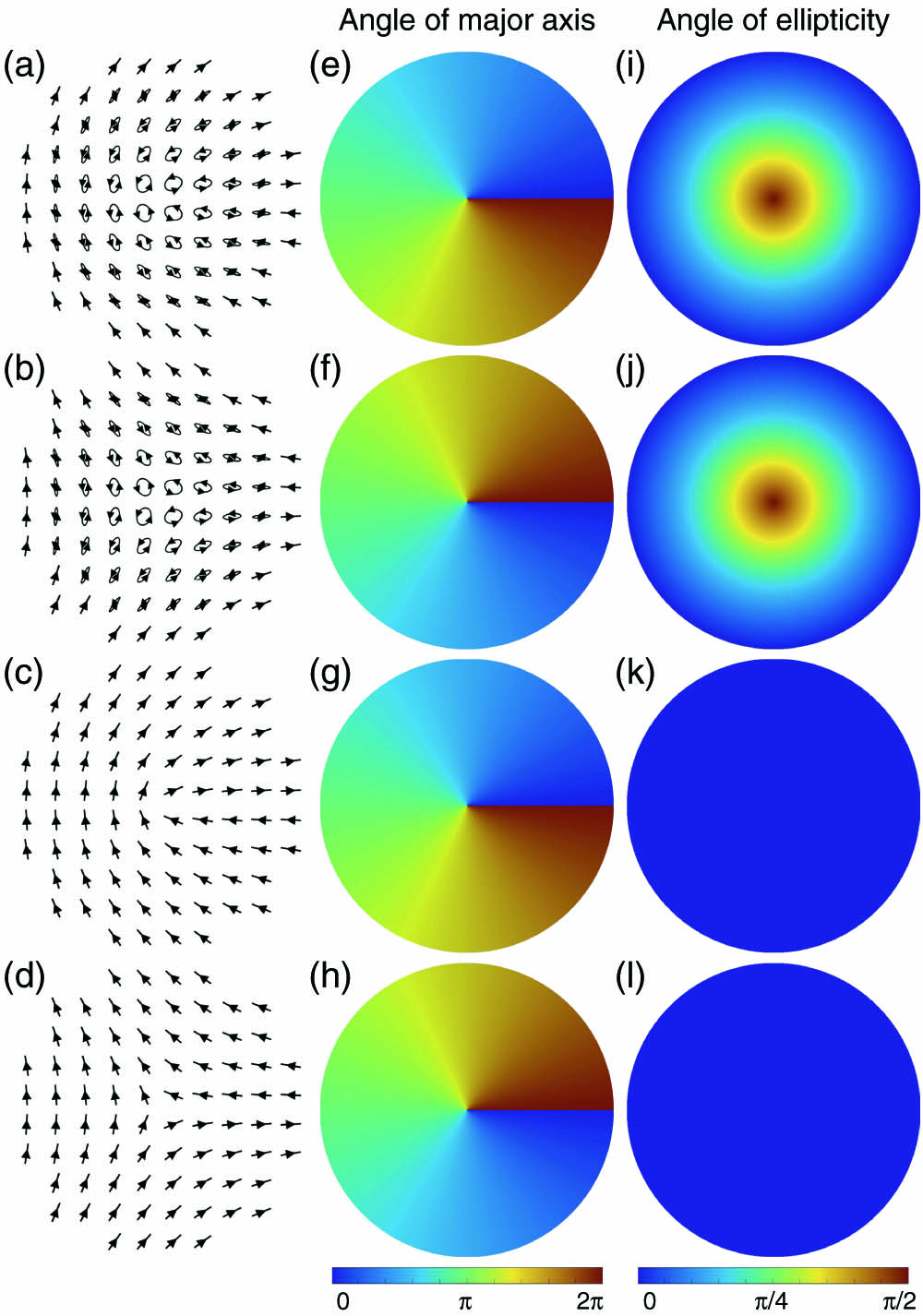
Now we introduce several VOFs containing polarization singularities. Figure 1 shows four different VOFs, whose centers are named as polarization singularities [1]. determines the distribution of the orientation of the polarization state, as shown in the second column in Fig. 1. When in Eq. (1), we can get lemon points, corresponding to Figs. 1(a) and 1(c)[11,12]. When in Eq. (1), we can get star points, corresponding to Figs. 1(b) and 1(d)[11,12]. Lemon points have a polarization topological index , and star points have [9,12].
Figure 1.Distributions of polarization states of four polarization singularities. (a) Lemon C-point with and , (b) star C-point with and , (c) lemon V-point with and , and (d) star V-point with and . (e)–(h) Corresponding distributions of the orientation angles of the major axes of polarization states to (a)–(d), respectively. (i)–(l) Corresponding distributions of the angles of ellipticity of the polarization states to (a)–(d), respectively.
The angle of ellipticity of the polarization state is determined by the parameter , with , as shown in the third column in Fig. 1. Singularities in Figs. 1(a) and 1(b) are called C-points (points of circular polarization), in which the orientations of the polarization states are undefined [7,9–13]. C-points can be realized by setting . Singularities in Figs. 1(c) and 1(d) are called V-points, in which both the orientations and handedness of the polarization states are undefined [13]. V-points can be realized by setting .
3. EXPERIMENTS AND DISCUSSION
A. Experimental Setup
To generate the arbitrary VOFs in the experiment, we need a spatial light modulator (SLM) and a system, as shown in Fig. 2. SLM is located in the input plane of the system. The amplitude transmission function of holographic grating displayed on SLM is where is the spatial frequency of the holographic grating, and is the additional phase distribution. In fact, the holographic grating is a two-dimensional cosine grating carrying the space-variant phase , so it diffracts the input optical field into four diffracted orders (st orders in both the and dimensions). To generate the VOFs we desire, the two st orders in the and dimensions are selected by a spatial filter (SF) located in the Fourier plane of the system. If two quarter-wave plates are placed in the Fourier plane of the system, the two bases for generating the VOF are the right- and left-handed circularly polarized fields, and the output VOF can be described by just Eq. (1). Any VOF can be generated because of the high flexibility of SLM. A Ronchi grating is located in the output plane of the system, which can be regarded as the plane of the generated VOF. So, the distribution of propagation states of the VOF can be measured by moving the CCD camera.
The light source used in the experiment is a laser with a wavelength of 532 nm, output power of 5 W, and spectral linewidth of 5 MHz (Verdi V5, Coherent Inc.). The SLM has a size of pixels with a pixel pitch of 8.0 μm (Pluto-2-vis-016, Holoeye Systems Inc.). The CCD camera has a size of pixels with a pixel pitch of 6.45 μm (1501C-USB, Thorlabs Inc.). Lenses L1 and L2 expand the laser beam into 9 mm in diameter, and lenses L3 and L4 have the same focal length of 250 mm (see Fig. 2). The generated vector fields have a top-hat-like shape in intensity. At the plane, the VOFs all have the same diameter of 9 mm.
B. Evolution of Singular Lines in the V-Point Case
The measured results show that the singular lines lead to evolution in all dimensions of polarization states. The initial singularity is caused only by the uncertainty of the orientation of the polarization states. For the V-points, we find a kind of change in symmetry. To further explore this phenomenon, the beam propagation method (BPM) [19] is used for simulation. The experimental results can be seen in Figs. 3 and 4. It should be emphasized that we plot the images only in the vicinity of the center of beam. The intensity in the initial plane is uniform, except for a thin dark line along the direction. This dark line becomes thicker and thicker as the propagation distance increases, as shown in Fig. 3.
Figure 3.Measured intensity distributions around a lemon V-point () at different propagation distances as , 0.4, 0.7, and 1.0 m.
Figure 4.Distributions of the intensity and polarization states around a V-point at a propagation distance . First, second, and third rows show the intensity, orientation angles of the major axes of polarization states, and angle of ellipticity, respectively. First (third) column shows the simulated results with (2.5), and second (fourth) column shows the corresponding measured results.
Figure 4 shows both simulated and measured results on the intensity, orientation angles of the major axes of polarization states, and the angle of ellipticity, at a propagation distance . The distributions of the intensity in Figs. 4(a)–4(d) and the polarization states in Figs. 4(e)–4(l) exhibit almost the mirror-symmetry property of the dark singular line along the axis. On both sides of the dark singular line, there appear two symmetrical strongest lines for in Figs. 4(a) and 4(b), while there occur two slightly modulated symmetrical strong lines and a horseshoe-shaped pattern for in Figs. 4(c) and 4(d).
We now investigate the structure of polarization states in the vicinity of the singular line. The polarization states exhibit regularly distributed singularities around the center of the beam whose number is 2 int(m), where int is the integer-valued function. There are two chains of singularities along the direction. Singularities of the lemon and star appear alternately on the chains. The so-called lemon (star) singularity is that the orientation angle of the polarization states surrounding it varies from 0 to clockwise (anticlockwise), as shown in Fig. 4(e), corresponding to Figs. 1(e) and 1(g). The chains of polarization singularities are investigated first by Ref. [17], and a perfect realization of Hilbert’s hotel is found as grows.
C. Evolution of Singular Lines in the C-Point Case
For C-points, the evolution of the singular line is asymmetric, and simulated and measured results can be found in Fig. 5. There seems to be a tendency that the singular line is pulled to one side to destroy the symmetry, and the total distribution looks a bit like the fractional phase situation [2]. As the beam propagates, this tendency does not become more apparent, while the whole pattern becomes larger. On both sides of the dark singular line, there appear two strongest lines for , while there occur two intensity-descending strong-spot chains for . The dark line becomes thicker as the propagation distance increases, the same as the V-point case.
Figure 5.Distributions of the intensity and polarization states around a C-point at a propagation distance . First, second, and third rows show the intensity, orientation angles of the major axes of polarization states, and angle of ellipticity, respectively. First (third) column shows the simulated results with (2.5), and second (fourth) column shows the corresponding measured results.
Admittedly, the arbitrary polarization state comes from the superposition of the eigen right- and left-handed circular polarizations with the reverse additional phases; therefore, the propagating evolution of polarization originates from the superposition of the evolution of the additional phases. As shown in Fig. 6, the optical fields of the points surrounding the V-point are the equal-weighted superposition of right- and left-handed circularly polarized components carrying the opposite vortex phases. The polarization states at all points surrounding the V-point are linearly polarized with different orientations, i.e., these polarization states are located on the equator of the Poincaré sphere. The symmetries in equal weight, right- and left-handed circular polarizations, and the opposite vortex phases result in symmetric evolution. Similarly, we easily understand the asymmetric evolution of the C-point, which originates from the asymmetry of unequal weight.
Figure 6.Any polarization state can be seen as a superposition of right- and left-handed circularly polarized components carrying the phases. (a) Polarization states at all points surrounding the V-point are linearly polarized but different in orientation, which are located on the equator of the Poincaré sphere. (b) Polarization states at all points surrounding the C-point are elliptically polarized but different in orientation, which are located on a certain latitude in the northern (or southern) hemisphere of the Poincaré sphere.
In terms of the whole polarization distribution of a VOF, if the initial polarization state is located on the equator of the Poincaré sphere, the evolution of polarization state in the propagating process will cover the entire Poincaré sphere. If the initial polarization state is confined on a hemisphere of the Poincaré sphere, however, the evolution will be confined only on this hemisphere. In addition, we can get the accurate locations of the singularities in the singularity chain in Fig. 4(e) (as an example). If we seek the accurate values of their angle of ellipticity in Fig. 4(i), they are or , which means that the chain is composed of C-points. In the propagation process, the VOF shows its own essential feature; both V-point and C-point singular lines evolve into chains of C-points, implying that C-point is natural and generic [1], i.e., C-point is the most basic topological singularity in the dimension of polarization.
D. Topological Property of the Vector Optical Field
We confirm that the VOF has a topological property, which means that there is a conserved quantity for the VOF in the propagation process. We define the lemon and star to be and . We find that this conserved quantity is the algebraic sum of lemon and star singularities. The algebraic sum of lemon and star singularities should be counted in the whole optical field. These singularities exist in the vicinity of the center of the optical field and on the singularity chains. In fact, the lemon and star singularities on the singularity chains appear alternately and in pair [17], so they all cancel to zero. Hence, we can be concerned with just the number of singularities near the center of the optical field, which are easily counted. The blue dots in Fig. 7 indicate the algebraic sum of lemon and star singularities counted in the whole optical field from the simulated results, and they have a jump at every half-integer value.
Figure 7.Comparison of the polarization topological index and algebraic sum of the singularities of vector optical fields with different topological charge .
In fact, the well-known topological invariant in the VOF is the polarization topological index , which is defined as , where is a closed path [1]. The red line in Fig. 7 indicates the integrated results of the polarization topological index . We can find that the value of the algebraic sum of singularities is double that of . So we can say that we have found an easy way to calculate the polarization topological index of the VOF, which is to count the algebraic sum of singularities in the whole optical field.
E. Locations and Number of the Singular Line
There exists only one singular line no matter how changes. Can this rule be broken? Here we make an attempt and successfully change the locations and number of the singular line.
Sign up for Photonics Research TOC. Get the latest issue of Photonics Research delivered right to you!Sign up now
For the design method, we obey the following steps: (1) using the rotation matrix to get a new coordinate, as , where ; (2) calculating the new azimuthal angle, as ; (3) performing the multiple design as and , where ; (4) replacing in Eq. (1) by such a new , we obtain a new VOF. Figure 8 shows the distributions of the orientation angles of the polarization states of the VOF containing a V-point, where Fig. 8(a) is the basic case, Fig. 8(b) is a triple case with and , and Fig. 8(c) is a triple spiral case with and . The corresponding results of the propagation evolution are shown in Fig. 9.
Figure 8.Distributions of the orientation angles of the major axes of the polarization states for different singular lines. (a) Single straight singular line case, (b) triple straight singular case ( and ), and (c) triple spiral singular case ( and ).
Figure 9.Illustration of the experimentally measured intensity and polarization distribution of the ternary case [(a)–(c)] and the ternary spiral case [(d)–(f)] at a propagation distance . (a), (d) Intensity; (b), (e) orientation angles of the major axes of the polarization states; and (c), (f) angle of ellipticity.
In Fig. 9, although the locations and number of singular lines are changed, the polarization distributions in the vicinity of each singular line have no significant change. This method may contribute to the research of complex optical fields.
4. CONCLUSION
We theoretically designed and experimentally realized fractional polarization vortices, e.g., V-points and C-points with lemon and star patterns, and high-order cases. The polarization singular lines are due to the orientation uncertainty of the polarization states, caused by non-integer topological charges. The results reveal that during propagation, evolution of the polarization singular lines results in the special intensity pattern, distribution of polarization states, and chains of polarization singularities. We also proposed a method to generate the triple straight and spiral singular lines, and studied their complex propagation and evolution process.
A polarization singular line will result in an intensity dark line in the initially generated vector field. In fact, such a vector field with a dark line is very similar to a traditional optical field blocked by a very thin obstacle. The propagation evolution of such a blocked optical field is well known, which can be obtained by simulation using the BPM or Fresnel diffraction method, etc. Under the paraxial condition, its propagation behavior can also be understood by the Fourier analysis. During propagation, the high spatial frequency components of the optical field blocked by the obstacle are lost, resulting in the appearance of the broader dark line. In fact, the very high spatial frequency components can be considered as the evanescent wave, because their wavevectors in the propagation direction are imaginary.
Acknowledgment
Acknowledgment. We acknowledge the support from the Collaborative Innovation Center of Extreme Optics.