
Wanli FANG, Lili SHEN, Haiyan LI, Xinyu CHEN, Zongqi CHEN, Chunhui SHOU, Bin ZHAO, Songwang YANG. Effect of Film Formation Processes of NiOx Mesoporous Layer on Performance of Perovskite Solar Cells with Carbon Electrodes [J]. Journal of Inorganic Materials, 2023, 38(9): 1103
- Journal of Inorganic Materials
- Vol. 38, Issue 9, 1103 (2023)
Abstract
In the past decade, PCE of PSCs has achieved 25.7%[1]. However, commercializing PSCs is still challenging due to the issues of large-area preparation and long-term stability[2], which C-PSCs hold promise to address[3]. HTL-free C-PSCs exhibit lower efficiency compared to metal-based devices due to the energy level mismatching (0.4 eV) between valence band maximum (VBM) of MAPbI3 (-5.4 eV) and carbon electrode (-5.0 eV)[4], which is unfavorable for the hole extraction. Additionally, the ineffective charge extraction and increased charge recombination derive from poor PVK/ carbon interface contact. Therefore, it’s necessary to develop an effective, low-cost and highly stable p-type inorganic HTL such as CuSCN, NiOx and MoOx[5⇓-7] to construct a normal n-i-p structured C-PSC[8].
In 2015, NiOx mesoporous layer was firstly deposited on the insulating ZrO2 or Al2O3 layer to establish PSC with normal n-i-p structure, and PCE of 14.9%[9] and 15.03%[10] was achieved respectively. However, PCE of the NiOx based n-i-p structured C-PSCs with MAPbI3 materials is not satisfactory during subsequent research. Since superior conductivity and zero band gap characteristics of graphene can be exploited to improve device performance[11], Tao, et al[12] modified HTL by using NiOx/graphene to achieve a PCE of 11.72%. Bhandari, et al[13] enhanced the efficiency of C-PSCs to 14.2% by further optimizing the carbon electrode. However, there are no relevant studies that relate the quality of mesoporous NiOx films to the performance of C-PSCs.
In order to improve PCE of NiOx-based C-PSCs, NiOx mesoporous layer with uniform thickness and well-distributed pores is necessary. In this work, spin-coating and screen-printing processes were used to prepare NiOx mesoporous films to investigate the effect of film formation processes of NiOx mesoporous layer on the performance of C-PSCs.
1 Experimental
1.1 Materials
Ethanol (EtOH, 95%) and 4-hydroxybutanoic acid lactone (GBL, 99.99%) were purchased from Aladdin Reagent. Lead iodide (PbI2, 99.99%) was purchased from Xi'an Polymer Light Technology Corp. Methylammonium iodide (MAI, 99.9%) and 5-ammonium valeric acid iodide (5-AVAI) were purchased from Greatcell Solar. Ni(NO3)2·6H2O was purchased from Sigma-Aldrich. NaOH (99.99%) was purchased from Aladdin Reagent. All chemicals were used without further purification.
1.2 Preparation of NiOx nanoparticles
NiOx nanoparticles were synthesized by a chemical precipitation method[14]. Ni(NO3)2·6H2O (0.5 mol) was dispersed in deionized water (100 mL), and pH of the solution was adjusted to 10 by adding NaOH solution (10 mol/L). After stirring for 15 min, the colloidal precipitation was washed with deionized water and dried at 80 ℃ for 6 h. Then it was calcined at 270 ℃ for 2 h. Finally, the synthesized nanoparticles were dispersed in deionized water. For the screen-printing paste, it was prepared with ethyl cellulose as the binder and terpineol as the solvent.
1.3 Preparation of perovskite solution
PbI2 (0.5761 g), MAI (0.1953 g), and 5-AVAI (0.0152 g) were dissolved in a mixed solution of GBL (800 µL) and EtOH (200 µL).
1.4 Device fabrication
The FTO glass substrates were etched by laser and cleaned sequentially in detergent, deionized water, and ethanol for 60 min. Then, a dense TiO2 blocking layer, followed by mesoporous TiO2, ZrO2, NiOx (or 60 µL, 3000 r/min, 60 s for spin-coating process), and carbon layers were screen-printed in sequence. Each layer was dried at 100 ℃ for 10 min, and annealed at 510 ℃ for 30 min (except for the carbon layer which was annealed at 430 ℃ for 30 min). Finally, perovskite solution was dropped onto the carbon layer and annealed at 50 ℃ for 60 min. The derived devices were labeled as device A (TiO2/ZrO2/carbon), device B (TiO2/ZrO2/NiOx(spin- coated)/carbon), and device C (TiO2/ZrO2/NiOx(screen- printed)/carbon), respectively.
2 Results and discussion
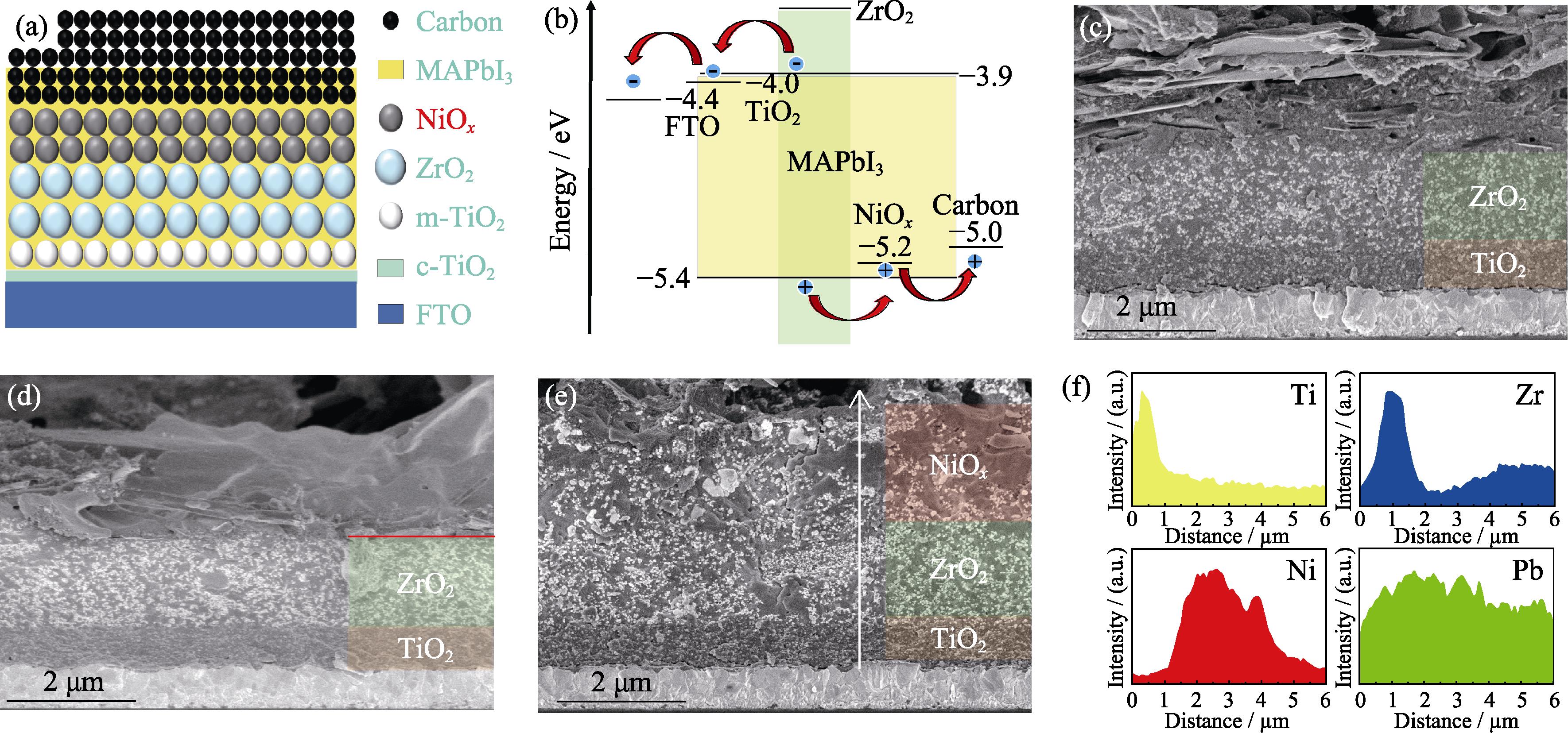
The device structure is FTO/TiO2/ZrO2/NiOx/carbon with PVK grains filled in the mesoporous scaffold in Fig. 1(a). Fig. 1(b) indicates that VBM of NiOx (-5.2 eV) matches well with MAPbI3 (-5.4 eV) due to its lower energy level than carbon (-5.0 eV)[15]. Thus, the existence of NiOx layer provides a better energy band alignment with PVK, which is beneficial to the extraction of holes.
![]()
Figure 1.(a) Schematic illustration and (b) work function of the device, cross-sectional SEM images of C-PSCs: (c) device A, (d) device B and (e) device C, and (f) element distribution in the direction of the white arrow in (e)
This work compared spin-coating and screen-printing methods to achieve high-quality NiOx mesoporous films. XRD pattern of synthesized NiOx nanoparticles is shown in Fig. S1. Fig. 1(c-e) present the cross-sectional SEM images of different devices. It can be observed that the thicknesses of the carbon layers are almost the same for all devices (Fig. S2). Fig. 1(f) confirms the successful deposition of different mesoporous layers through the element distribution mapping of Ti, Zr, Ni, and Pb. Moreover, the relative homogeneity of the lead signal intensity in the profile indicates that the perovskite is uniformly filled in the scaffold. In Fig. 1(d, e), it’s obvious that the NiOx layer deposited by spin-coating is too thin to be identified, possibly due to the dispersed NiOx nanoparticles in deionized water penetrating the hollows in the ZrO2 underlay. To confirm this, the NiOx nanoparticle dispersion and the screen-printable paste were left to stand for 30 min, respectively. The NiOx nanoparticle dispersion for spin-coating was observed to precipitate after 30 min of storage, while the screen- printable paste remained well-dispersed without any delamination, as shown in Fig. 2. This is attributed to the difference in solvents and binders used for the spin- coating NiOx dispersion and screen-printing NiOx paste.
![]()
Figure 2.Photographs of NiO
The top view SEM images of the ZrO2 film, spin-coated, and screen-printed NiOx mesoporous films are presented in Fig. 3(a-c), respectively. The high-magnification SEM images of the screen-printed ZrO2 and NiOx film are placed in Fig. S3. It is worth noting that the screen- printed NiOx film has well-distributed pores, which benefits the penetration of the perovskite precursor solution, while the spin-coated NiOx film has poor coverage and a relatively dense surface. To investigate the effect of the NiOx mesoporous layer on charge extraction, photoluminescence (PL) tests were carried out. The results in Fig. 3(d) show that the PL emission is significantly suppressed with the insertion of the NiOx mesoporous layer, especially for sample C (ZrO2/NiOx(screen-printed)/MAPbI3), which means more efficient hole extraction in ZrO2/NiOx/MAPbI3 interface. Moreover, the PL peak of sample C exhibits a slight blue shift compared to the other samples, indicating decreased trap state and reduced defect density of MAPbI3 film[16].
![]()
Figure 3.SEM images of (a) ZrO2 mesoporous film, (b) spin- coated and (c) screen-printed NiO
To investigate whether NiOx mesoporous layer affects the crystallinity of MAPbI3, XRD patterns of devices were carried out. The diffraction peak at 2θ=26.4° corresponds to SnO2 of the FTO substrate (Fig. 4(a)). Device C has the narrowest half-peak width of (110) plane implying large grains (Fig. 4(b)), possibly due to its large pores for the permeation and crystallization of perovskite grains. It should be noted that the valence state of Ni affects the interfacial oxidation and thus the recombination of carriers[17]. In this work, the effect of the valence state of Ni is similar due to the same post-treatment processes for NiOx mesoporous films.
![]()
Figure 4.(a) XRD patterns of MAPbI3 in different devices and (b) local magnified XRD patterns in range of 13.6°-14.6°
The current density-voltage (J-V) curves and photovoltaic parameters of different devices are shown in Fig. 5(a) and Table S1, respectively. The high quality NiOx HTL can significantly improve VOC and slightly improve JSC compared to device A. Device A shows the worst performance with a PCE of 11.62%, which may be due to poor interface contact and energy level mismatching at the PVK/carbon interface. It is concluded that the quality of the NiOx HTL affects the efficiency of the device. PCEs of Device C and B achieved 13.49% and 11.78%, respectively. The hysteresis index (HI) was calculated using equation (1)[18] to describe the hysteresis behavior of PSCs.
![]()
Figure 5.(a-c)
Device C has the lowest HI of 0.0067, indicating negligible J-V hysteresis, compared to device A (HI=0.1472) and device B (HI=0.0119). The spin-coated NiOx HTL does not apparently enhance the performance of C-PSCs. So, device A and device C were compared subsequently.
The thickness of the screen printed NiOx mesoporous layer has a decisive influence on PVK/carbon interface and series resistance, and the highest PCE was achieved when the thickness was 1.6 μm (Fig. 5(b)). A reduction in thickness is not conducive to interfacial contact, while an increase in thickness increases series resistance. Table S2 lists the specific photovoltaic parameters.
Fig. 5(c) presents J-V curves of the optimum devices. Their corresponding photovoltaic parameters are shown in Table S3. Device A exhibited PCE of 11.95% with VOC of 0.840 V, JSC of 23.39 mA·cm-2, and FF of 0.61. While device C exhibited PCE of 14.63% with VOC of 0.910 V, JSC of 25.04 mA·cm-2, and FF of 0.64. Improvements of JSC by 7.1% and FF by 5.1% were observed when the high quality NiOx mesoporous layer is employed. The increase in device efficiency is mostly due to the increment in VOC, from 840 mV to 910 mV. Fig. 5(d) shows the corresponding IPCE spectra and integrated current density curves of the devices. Compared with device A, device C has higher IPCE over the whole wavelength ranging from 300 nm to 850 nm, illustrating more efficient utilization of sunlight for C-PSCs. However, the value of integrated current density is lower than that of J-V test, probably because the device is not fully activated, which is related to light intensity[19]. The performance of devices was further testified for certification measurement with PCE=14.88%, VOC=0.882 V, ISC=1.87 mA, and FF= 63.19% (Fig. S4), which indicates the reliability of laboratory results and superior performance of this work.
The dark J-V curves of devices in Fig. 6(a) can provide important information, such as shunt resistance (Rsh), series resistance (Rs), leakage current, and diode characteristics. Device C exhibited more ideal diode characteristics compared to device A, and the ideality factor, n can be calculated using the slope and formula (2)[20]:
![]()
Figure 6.(a)
Where kB=1.380649×10⁻²⁶ J·K-1, qe=1.6×10⁻¹⁹ C, and T represent Boltzmann constant, the elementary charge, and temperature (K), respectively. Here n=1.35 for device C, which is significantly lower than that of 3.01 for device A. Although the p-n junction equivalent circuit is usually used to simulate the perovskite solar cell, it is difficult to directly obtain the potential and n of each diode due to the inhomogeneous built-in electric field. So the overall n is typically used to evaluate the diode characteristics of the device[21-22]. Lower n accounts for the improved diode quality[23]. It can be seen that the dark current density of the device C is almost an order of magnitude lower than that of device A (Fig. 6(a)), implying less current leakage and charge recombination, but increased sheet resistance.
The dependence of VOC on light intensity was tested to further investigate the recombination behavior of charge carriers. Fig. 6(b) shows the linear fitting of VOC as a function of logarithmic light intensity (lgI) with different slopes. With calculation, n for device A and device C were 0.99 and 1.25, respectively. It is reported that n is related to defect-assisted recombination[24]. This confirms that high quality mesoporous NiOx film as HTL at PVK/carbon interface can reduce carrier recombination, consistent with PL spectra, which is beneficial to PCE.
The decay of photovoltage and photocurrent can reveal the transport and recombination process of photogenerated carriers. Restricting recombination at the PVK/carbon interface contributed to longer VOC decay time (Fig. 6(c)). The NiOx mesoporous layer reduces the recombination of photogenerated electrons and holes, thus improving the device's efficiency. Device C displayed a faster decay of photocurrent in the short- circuit state compared to device A in Fig. 6(d), indicating better charge extraction capability, which is attributed to the enhanced hole transport from the perovskite layer to the carbon electrode[25].
Electrochemical impedance spectroscopy (EIS) was used to investigate charge transport and recombination in the devices. The semicircle in the high-frequency range represents the charge transfer resistance (Rct) at the interface, and the semicircle in the low-frequency region represents the charge recombination resistance (Rrec) in the device[26]. As shown in Fig. 6(e), device C exhibits smaller semicircle in the high-frequency region and larger semicircle in the low-frequency region, indicating more efficient charge transfer and transport.
Mott-Schottky analysis was conducted to explain the improved VOC in device C. The built-in potential (Vbi) of the device was determined by fitting the linear portion of the C-2-V curve using equation (3)[27].
Where C, A, N, q, ε, ε0, and V represent capacitance (F), active area (cm2), the concentration of donor-dopant (cm-3), elementary charge (C), relative permittivity, the permittivity of free space, and applied bias, respectively. It was reported that VOC depends on Vbi[28]. In this work, Vbi is 0.81 V for device C and 0.75 V for device A. It is concluded that high quality NiOx mesoporous layer optimizes the energy level arrangement, enhances the built-in potential, and reduces the loss of VOC in the device.
Stability is a crucial factor for the commercialization of PSCs. C-PSCs are more stable due to the hydrophobic nature of carbon electrodes. Unencapsulated devices were stored for nearly 900 h, and their evolution in JSC, VOC, FF, and PCE were monitored in Fig. 7(a-d). At the initial 20 h, all parameters, except JSC of device C, increased possibly due to further crystallization of perovskite grains induced by solvent evaporation. Both devices' VOC increased due to the recrystallization of filled perovskite in mesopores under the combined action of water and oxygen[29]. JSC decreased over time, while the general trend of the evolution of FF and PCE was similar. NiOx-based C-PSCs showed better stability than C-PSCs without HTL.
![]()
Figure 7.Long-term storage stability of PSCs in air with relative humidity of 30%-40%(a)
3 Conclusions
This work demonstrates the importance of the film formation process of the p-type NiOx mesoporous layer in improving the efficiency and stability of C-PSCs. The results show that the NiOx mesoporous film prepared by screen-printing progress with well-distributed pores allows for better penetration of the perovskite precursor solution, leading to a significant improvement in efficiency of C-PSCs from 11.95% to 14.63%, with a certified efficiency of 14.88%. Additionally, the device maintains its efficiency for nearly 900 h without degradation. These findings have important implications for the commercialization of C-PSCs.
Supporting materials
Supporting materials related to this article can be found at
FANG Wanli1,2, SHEN Lili2, LI Haiyan2, CHEN Xinyu2, CHEN Zongqi2, SHOU Chunhui3, ZHAO Bin1, YANG Songwang1,2,4
(1. School of Materials and Chemistry, University of Shanghai for Science and Technology, Shanghai 200093, China; 2. CAS Key Laboratory of Materials for Energy Conversion, Shanghai Institute of Ceramics, Chinese Academy of Sciences, Shanghai 201899, China; 3. Key Laboratory of Solar Energy Utilization & Energy Saving Technology of Zhejiang Province, Zhejiang Energy Group R&D, Hangzhou 310003, China; 4. Center of Materials Science and Optoelectronics Engineering, University of Chinese Academy of Sciences, Beijing 100049, China)
Characterization
The FE-SEM (Thermo-scientific G4 UC) was used to observe the surface morphology of the NiOx mesoporous layer prepared by different processes and the cross- sectional morphology of the corresponding devices. The elemental distribution is obtained by energy dispersive X-ray spectroscopy (EDX), which is measured by AMETEK EDAX configured with FE-SEM. Steady-state photoluminescence (PL) spectra were measured by the FluoroMax-4 steady-state fluorescence test system, and the samples were exited at 532 nm and labeled as sample A (ZrO2/MAPbI3), sample B (ZrO2/NiOx(spin-coated)/ MAPbI3), and sample C (ZrO2/NiOx(screen-printed)/ MAPbI3), respectively. The X-ray diffractometer (XRD) was characterized by D8 advance with Cu Kα radiation (40 kV, 40 mA). The photovoltaic parameters were measured under 1 sun illumination (100 mW·cm-2) by a solar simulator (Yamashita Denso YSS-150A). The light intensity is calibrated by a standard silicon solar cell with a filter (BS-520BK, Bunkoh-Keiki Co., Ltd). The effective area is defined as 0.07 cm2 by using a mask. The incident photon-to-electron conversion efficiency (IPCE) spectra were measured with a test step length of 10 nm by Bunkoh-Keiki's CEP-1500 test system. The dark I-V, light-intensity dependence of VOC, transient photovoltage decay curves, transient photocurrent decay curves, electrochemical impedance spectroscopy (EIS), and Mott-Schottky (M-S) were performed on Zahner CIMPS- pro electrochemical workstation.
![]()
Figure S1.XRD pattern of NiOx nanoparticles prepared by chemical precipitation method
![]()
Figure S2.Low magnification cross-sectional SEM images of (a) device B and (b) device C
![]()
Figure S3.High magnification top-view SEM images of screen- printed (a) ZrO2 and (b) NiOx films
| Sample | VOC/V | JSC/(mA·cm-2) | FF/% | PCE/% | ||||
|---|---|---|---|---|---|---|---|---|
| Reverse | Forward | Reverse | Forward | Reverse | Forward | Reverse | Forward | |
| Device A | 0.779 | 0.764 | 23.45 | 23.38 | 63.60 | 55.47 | 11.62 | 9.91 |
| Device B | 0.822 | 0.820 | 23.62 | 23.56 | 60.66 | 60.26 | 11.78 | 11.64 |
| Device C | 0.904 | 0.903 | 23.57 | 23.56 | 63.29 | 62.98 | 13.49 | 13.40 |
Table 1.
Photovoltaic parameters for different devices with an aperture area of 0.07 cm2 under 1 sun (100 mW·cm-2) illumination
![]()
Figure S4.Certified efficiency measurement report of device C
| Sample | VOC/V | JSC/(mA·cm-2) | FF/% | PCE/% |
|---|---|---|---|---|
| NiOx (0.8 μm) | 0.898 | 22.36 | 61.66 | 12.38 |
| NiOx (1.6 μm) | 0.932 | 22.68 | 62.87 | 13.28 |
| NiOx (2.4 μm) | 0.939 | 20.86 | 54.43 | 10.66 |
Table 2.
Photovoltaic parameters of devices with different thicknesses of screen-printed NiOx layer
| Device | VOC/V | JSC/(mA·cm-2) | FF/% | PCE/% |
|---|---|---|---|---|
| Device A | 0.840 | 23.39 | 61.00 | 11.95 |
| Device C | 0.910 | 25.04 | 64.13 | 14.63 |
Table 3.
Photovoltaic parameters of device A and C
References
[18] Z LIU, B SUN, X LIU et al. Efficient carbon-based CsPbBr3 inorganic perovskite solar cells by using Cu-phthalocyanine as hole transport material. Nano-Micro Lett., 10, 34(2018).

Set citation alerts for the article
Please enter your email address
© Copyright 2018-2021 | Chinese Laser Press. All Rights Reserved 沪ICP备15018463号-20